5-Axis CNC Machining Services: Precision Multi-Axis Manufacturing
Our 5-axis CNC machining services use Computer Numerical Control (CNC) interpolation across X, Y, Z, and two rotary axes—simultaneously or in 3+2 indexed setups—holding critical features to ±0.010 mm (±0.0004″) and Ra 0.4 µm (16 µin). Our in-house facility delivers single-setup aerospace, medical, and robotics parts in 4–8 business days ex-factory (plus 3–5 days DHL/FedEx air transit).
1. What Is 5-Axis CNC Machining & How It Works
Five-axis CNC machining is a subtractive manufacturing process that articulates a cutting tool or workpiece across five degrees of freedom. Beyond conventional linear travel along the orthogonal X, Y, and Z axes, the machine coordinates two rotary axes (A and C, or B and C) to machine complex spatial geometries within ±0.010 mm (±0.0004″).
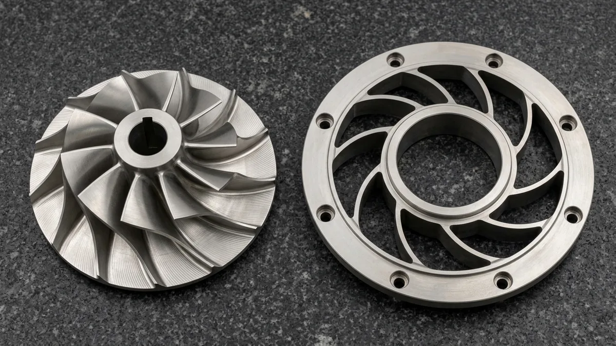
Approaching billet stock from compound angles in a single setup eliminates manual re-clamping and cumulative datum shift across mating turbomachinery stages. As shown in the paired Ti-6Al-4V swept rotor impeller and 8-hole flanged curved-vane stator diffuser ring in Figure 1, simultaneous 5-axis finishing maintains concentric hub bores, swept blade profiles, and smooth fillet radii.
2. What Does the “5” in 5-Axis Stand For? (Kinematic Coordinates)
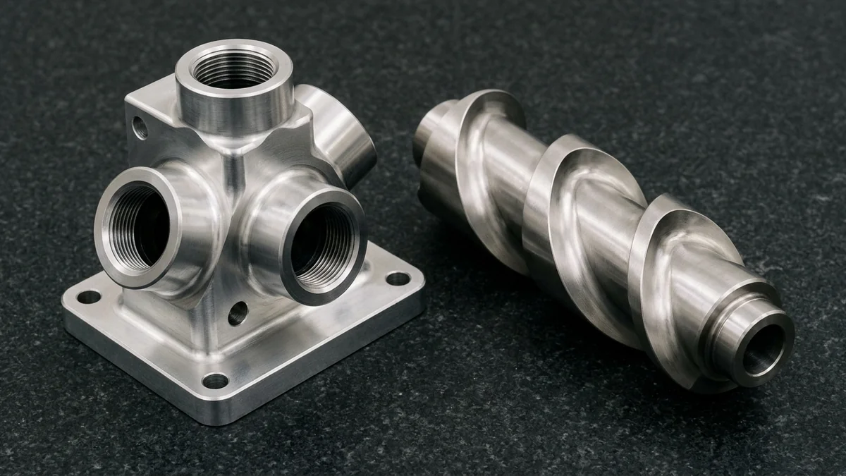
The designation “5” denotes five coordinate axes governing relative motion between cutter and workpiece. Adding two rotary axes to linear X, Y, and Z travel enables 3+2 indexed positioning for compound-angle aluminum manifold ports and continuous 5-axis interpolation for variable-pitch 316L stainless steel helical augers (Figure 2):
Linear
Linear
Linear
Rotational ±120°
Rotational 360°
Keeping the cutter normal to sculptured or compound-angled surfaces lets our trunnion spindle run stubby, rigid carbide end mills (L/D ≤ 3:1), suppressing tool deflection and chatter to achieve surface finishes down to Ra 0.4 µm (16 µin) on complex contours.
3. Core Configurations of 5-Axis CNC Machines
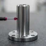
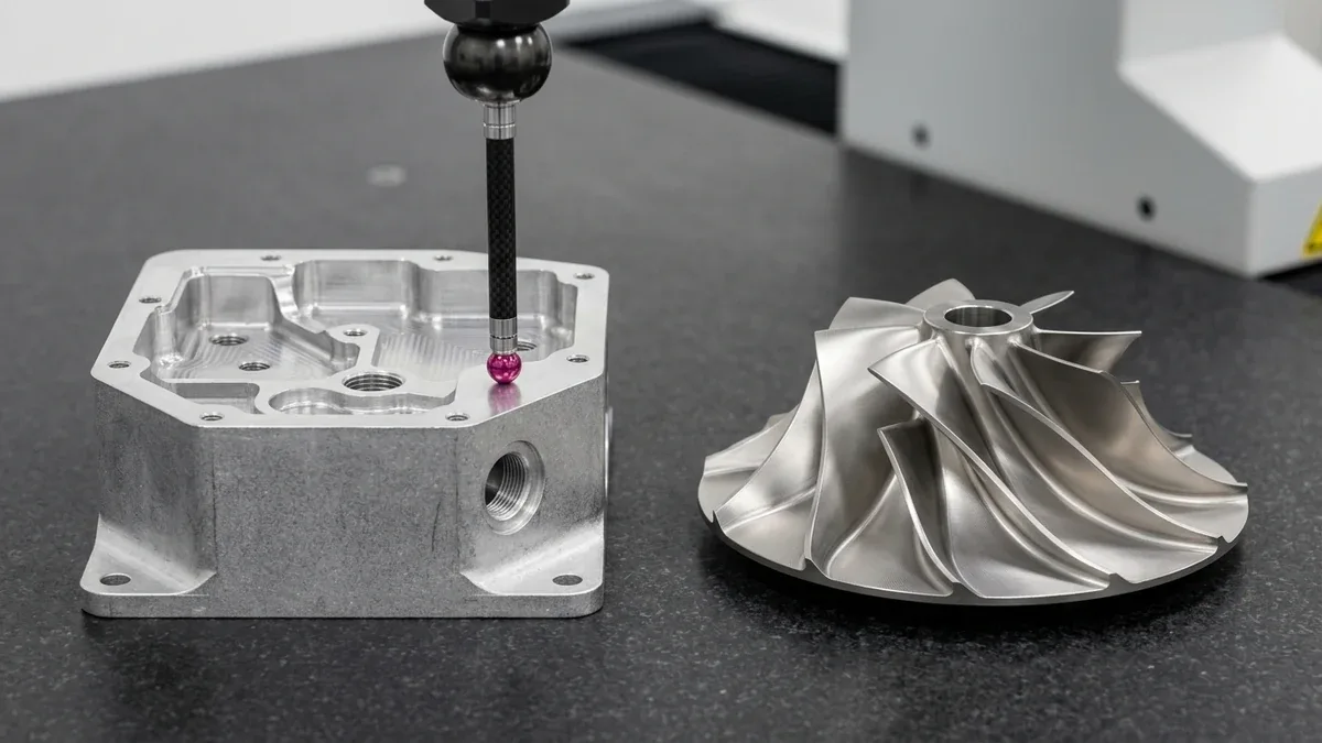
Five-axis CNC centers are built in three kinematic architectures defined by whether rotary motion resides in the spindle head, worktable, or both. Regardless of architecture, single-setup multi-face aluminum housings and titanium centrifugal impellers undergo vertical bridge Coordinate Measuring Machine (CMM) ruby-probe verification on their top horizontal flange datum in our metrology lab (see Figure 3):
Head-Head Configuration
Head-Table (Hybrid)
Table-Table (Trunnion)
4. Continuous 5-Axis (Simultaneous) vs. 3+2 Positional Machining (Indexed)
Selecting between Continuous Simultaneous 5-Axis and 3+2 Indexed Positional machining directly governs cycle time, CAM complexity, and part cost:
Continuous 5-Axis Machining interpolates all three linear and two rotary axes concurrently throughout cutting. Continuous vector motion sweeps smooth 3D aerodynamic surfaces without witness step marks, making simultaneous 5-axis essential for titanium impellers, blisks, variable-pitch helical augers, and contoured orthopedic implants.
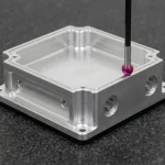
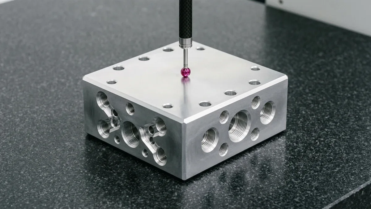
3+2 Indexed Machining tilts and pneumatically locks the rotary axes at discrete compound angles before executing rigid 3-axis milling. Machining compound-angled fluid ports in one setup preserves alignment to the flat top primary datum face—verified via vertical bridge CMM ruby probing on our black granite plate (Figure 4).
| Machining Category | Tool Kinematics | Achievable Critical Tolerance (mm / in) | Setup Count & Cost Ratio | Recommended Application / When to Choose |
|---|---|---|---|---|
| Continuous 5-Axis (Simultaneous) | X, Y, Z, A, and C axes interpolate concurrently during cutting | ±0.010–±0.015 mm (±0.0004″–±0.0006″) | 1–2 setups (OP10 + base flycut) · 2.2×–3.5× rate | Ti-6Al-4V impellers, blisks, helical mixing augers, and contoured aero-surfaces |
| 3+2 Positional (Indexed 5-Axis) | Trunnion tilted and locked at compound angle; rigid 3-axis cutting | ±0.010–±0.020 mm (±0.0004″–±0.0008″) | 1–2 setups · 1.3×–1.8× rate (cuts custom fixtures) | Angled-bore avionics sensor housings, compound hydraulic manifolds, canted yokes |
| High-Speed 3-Axis CNC Milling | Linear X, Y, Z motion only; spindle oriented vertically | ±0.010–±0.020 mm (±0.0004″–±0.0008″) | 2–5 setups for multi-face parts · 1.0× baseline | 2.5D planar plates, orthogonal brackets, cold plates, and standard enclosures |
5. Manufacturing Advantages: Single-Setup Precision & Geometric Freedom
Single-Setup Eliminates Datum Shift & Stack-Up Error
Superior Surface Finish (Ra 0.4–0.8 µm / 16–32 µin)
Compound Angles & Undercut Access
Elevated Self-Centering Workholding
20,000 RPM HSK-A63 Dynamic Milling
Ex-Factory Turnaround in 4–8 Business Days
6. Overcoming 5-Axis Engineering Challenges: AS Prototypes Capabilities
Simultaneous 5-axis CNC machining introduces strict engineering constraints—including trunnion collision envelopes, higher machine-hour rates, and thermal drift. Below is how our in-house engineering team controls these variables (for detailed CAM rules, see our 5-axis CNC complex workpiece guide and impeller 5-axis machining guide):
Challenge: Multi-Axis CAM Singularity, Gouging & Collision Risks
Challenge: Higher 5-Axis Hourly Rates & Setup Economics
Challenge: Multi-Axis Thermal Expansion Drift & Datum Verification
7. High-Precision Components & Compatible Engineering Materials
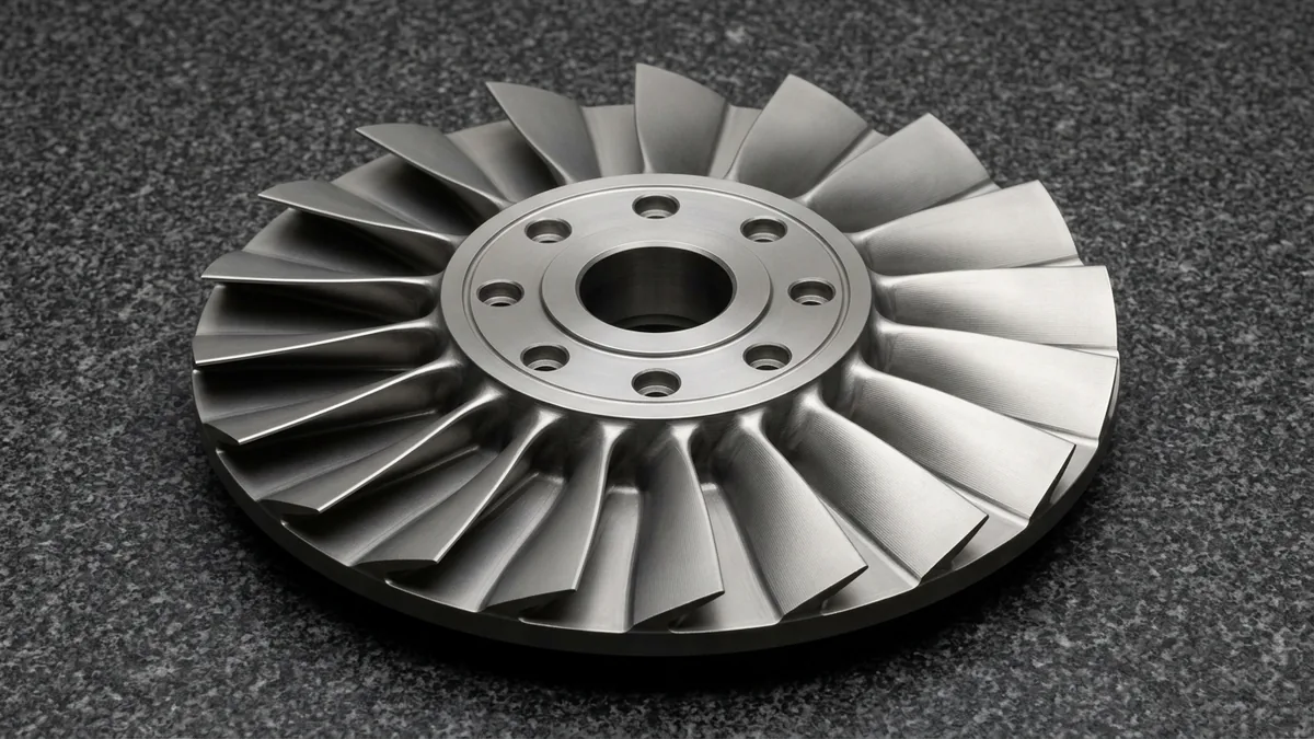
Sculptured Turbine Blisks & Impellers
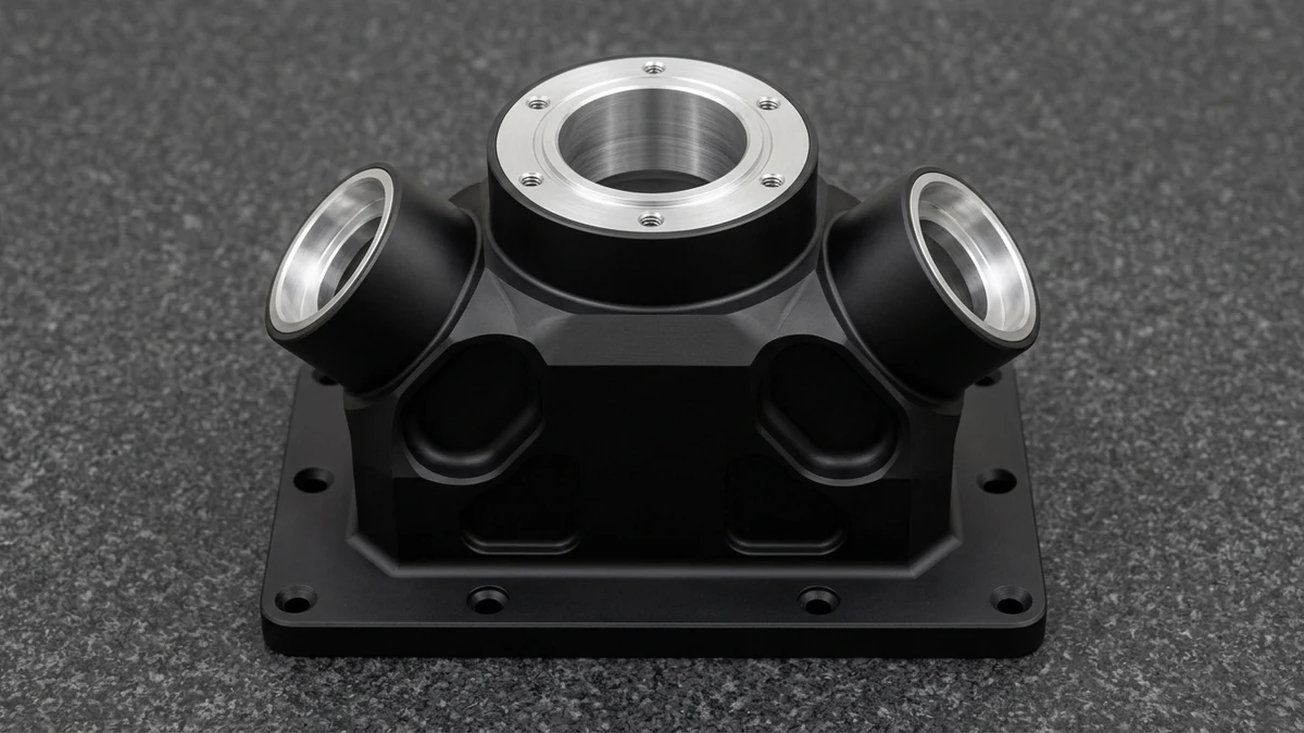
3+2 Angled-Bore Sensor Housings
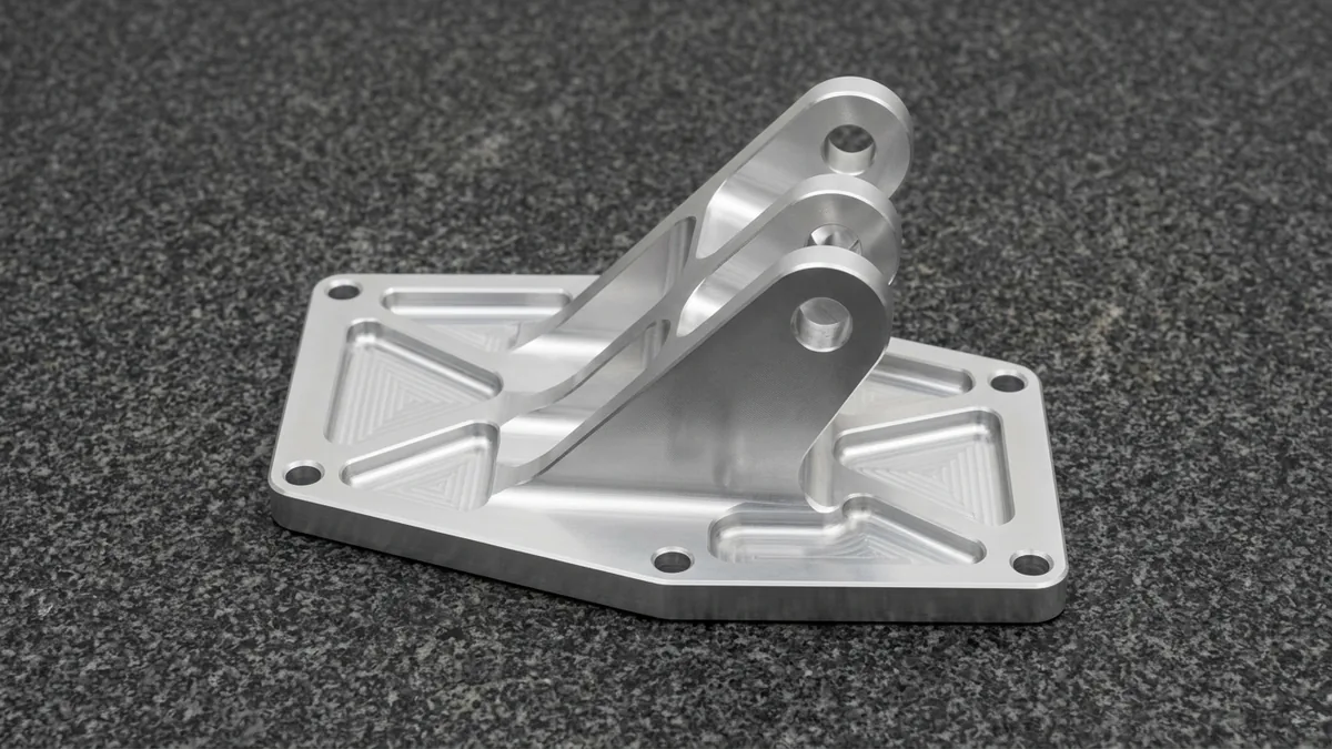
Canted Clevis Aerospace Brackets
- Aluminum Alloys: 6061-T6, 7075-T651 (503 MPa / 73 ksi yield strength for canted yokes; avoid fusion welding 7075-T651 due to hot-cracking—specify 6061-T6 or 5083-H112 for welded assemblies), and 2024-T351.
- Titanium & Superalloys: Ti-6Al-4V (Grade 5), CP Grade 2 titanium, and Inconel 718 machined with high-pressure coolant to suppress work-hardening layers and notch wear.
- Stainless & Alloy Steels: 316L, 304, 17-4PH (H900), 4140, and D2 tool steel; nitric/citric passivation per ASTM A967 (~0.002 µm zero dimensional growth).
- High-Performance Polymers & Anodizing: PEEK, POM-C (acetal copolymer), PTFE (soft PTFE general tolerance ISO 2768-c), PA66, and PEI; aluminum anodizing per MIL-A-8625 Type II / Type III (450–550 HV0.05) with silicone-plug masking or secondary post-boring on H7 (+0/+IT7) fits.
8. Demanding Industry Applications & Metrology Verification
Aerospace & Aviation →
Medical Devices & Implants →
Robotics & Automation →
Electro-Optical & Sensing →
9. In-House Multi-Axis Work Envelopes & Engineering DFM Matrix
| In-House Platform & Builder | Kinematic & Spindle Configuration | Max Work Envelope (mm / in) | Positioning & Feature Accuracy | Recommended Application / When to Choose |
|---|---|---|---|---|
| Simultaneous 5-Axis Trunnion (AFMING GMU-400) | A-tilt (±120°) + C-rotary (360°) · 20,000 RPM (HSK-A63) · Heidenhain TNC RTCP | Table Ø450 × 350 mm (17.7″ × 13.8″) | Machine ±0.008 mm (±0.0003″) · Critical features ±0.010 mm (±0.0004″) | Ti-6Al-4V centrifugal/axial impellers, blisks, helical augers, and 3D sculptured contours. |
| 3+2 Indexed Trunnion Mode (AFMING GMU-400) | Rotary brakes locked at compound (A, C) angles during rigid 3-axis cutting | Table Ø450 × 350 mm (17.7″ × 13.8″) | 30%–45% lower CAM & cycle cost vs. simultaneous; holds ⌀0.020 mm true position | Angled-bore avionics sensor housings, compound hydraulic manifolds, and canted dual-yoke brackets. |
| 4-Axis Direct-Drive VMC (Fanuc Robodrill α-D21LiB5 ×4) | X, Y, Z + synchronized direct-drive 4th rotary axis · 24,000 RPM spindle | 700 × 400 × 330 mm (27.6″ × 15.7″ × 13.0″) | Machine ±0.008 mm (±0.0003″) · High-speed radial indexing | Multi-sided tombstone parts, cylindrical radial cross-ports, and medium-length brackets. |
| Heavy & High-Speed 3-Axis VMCs (Mazak VCN-530C ×2 / Brother Speedio ×7) | 12,000 RPM (CAT40) heavy-duty & 16,000 RPM (BT30) high-speed 3-axis milling | Up to 1,050 × 530 × 510 mm (41.3″ × 20.9″ × 20.1″) | 75%–85% shopfloor workhorse capacity · Lowest unit machining cost | Large structural plates, orthogonal RF filter cavities, liquid cold plates, and planar enclosures. |
| 5-Axis DFM Parameter | Quantitative Engineering Design Standard | Recommended Application & Cost Benefit |
|---|---|---|
| 1. 3+2 Indexed vs. Simultaneous 5-Axis | Specify planar compound faces (3+2 indexed) unless true sculptured 3D flow surfaces are required | 3+2 positional indexing locks rotary brakes for higher feed rates and cuts CAM and machine-hour costs by 30%–45%. |
| 2. Dovetail & Sacrificial Clamping Stock | Allow 10–15 mm (0.40″–0.60″) sacrificial base stock for elevated 5-axis dovetail vise gripping | Provides unobstructed 5-face cutter clearance in OP10 without trunnion table collision, followed by simple OP20 base flycutting. |
| 3. Impeller & Blade Channel Width | Minimum blade channel width W ≥ 1.4 × tapered ball-nose cutter tip diameter (D_tip < 0.7 W) | Allows rigid 3° thermal shrink-fit tapered-neck ball-nose end mills (D3–6 mm) to finish blade roots without shank collision. |
| 4. Blade Root & Freeform Fillet Radii | Specify uniform root fillet radii R ≥ 1.0–2.0 mm (0.040″–0.080″) along 3D sculpted intersections | Permits larger ball-nose or circle-segment barrel cutters with wider step-overs, cutting 5-axis finishing cycle time significantly. |
| 5. Compound Angled Port Intersections | Add perpendicular spot-faced entry flats or 45° chamfers; keep cross-hole intersection angles ≥ 15° | Prevents carbide drill tip skidding on sloped manifold walls and enables clean automated 5-axis cross-port deburring. |
| 6. HSK-A63 Toolholder Tilt Clearance | Avoid deep vertical pockets immediately adjacent to tall bosses (height-to-gap ratio ΔH / Gap ≤ 3:1) | Ensures the HSK-A63 thermal shrink-fit toolholder nose maintains ≥ 15 mm clearance when tilting 30°–45° near upright walls. |
| 7. Unified ASME Y14.5 Datum Reference Frame | Anchor all compound-angled bores and faces to a single primary/secondary/tertiary (A|B|C) datum frame | Leverages single-setup 5-axis clamping to hold ⌀0.020 mm (⌀0.0008″) true position (or ±0.010 mm / ±0.0004″ datum-to-feature center distance). |
| 8. Reserve 5-Axis for True Multi-Axis Geometry | Route orthogonal enclosures, planar cold plates, and 2.5D brackets to high-speed 3-axis / 4-axis VMCs | Eliminates unnecessary 5-axis hourly rates on prismatic parts milled faster in a precision machine vise or contoured soft jaws. |
10. Frequently Asked Questions (5-Axis Machining FAQs)
What standard tolerances can AS Prototypes achieve on continuous 5-axis CNC machining?
What is the practical difference between simultaneous 5-axis and 3+2 indexed machining?
What 3D CAD formats are accepted for a custom 5-axis CNC quote?
How does AS Prototypes verify 5-axis part quality before shipment?
Ready to Precision-Machine Your 5-Axis Components?
Upload your 3D CAD models (STEP/IGES) and 2D tolerance drawings for a comprehensive manufacturability review, datum-locking strategy, and custom quotation within 24 hours.