Precision CNC Turning • Live Tooling Lathes • Precision Machining
Custom CNC Turning Services & Precision Lathe Machining
Precision Turning
±0.005 mm (Metals) / ISO 2768-m (Plastics)
Live Tooling Mill-Turn
Swiss Micro-Machining
50+ Production Materials
Zeiss CMM Metrology (Upon Request)
At AS Prototypes, our in-house machine shop operates high-precision CNC turning centers, multi-axis live-tooling mill-turn lathes, and Swiss-type screw machines. We manufacture tight-tolerance cylindrical prototypes and production runs with standard tolerances conforming to ISO 2768-mK and precision journal tolerances down to ±0.005 mm (±0.0002″).
How Does Precision CNC Turning Work?
CNC turning is a subtractive manufacturing process where solid cylindrical bar stock is clamped rigidly in a high-speed hydraulic chuck or collet and rotated at speeds up to 6,000 RPM. Stationary or live rotating cutting tools traverse along the X and Z axes to slice away excess material, carving precise external diameters, internal bores, threads, and tapers.
• Rotary Motion: The workpiece spins while single-point carbide inserts shear chips with constant surface speed (CSS).
• High Concentricity: All turned diameters machined in a single setup maintain concentricity within Ø0.010 mm (TIR ≤ 0.008 mm in single chucking).
• Live Tooling Capability: Driven rotary tool turrets perform radial milling, cross-hole drilling, and off-center tapping without re-fixturing.
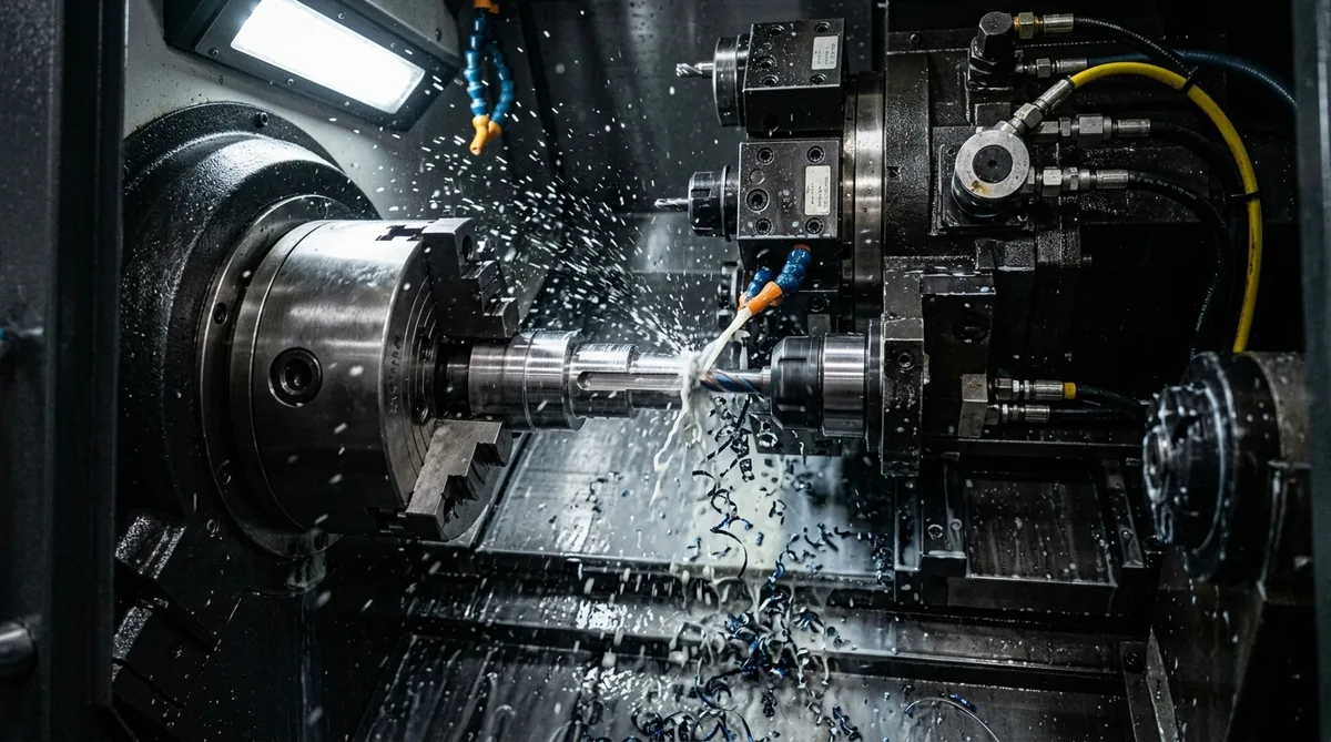
Live Tooling Turret & Hydraulic Main Spindle
Step 01
3D CAD & Sizing
Engineers evaluate STEP/IGES models and 2D prints for bar sizing, thread pitches, and GD&T runout requirements.
Step 02
CAM Toolpathing
CAM programmers simulate insert nose radius compensation, constant surface speeds, and chipbreaker geometry.
Step 03
Chuck Clamping
Hydraulic 3-jaw chucks or precision pie jaws lock the bar. Dial indicators ensure spindle runout TIR ≤ 0.008 mm.
Step 04
Turning & CMM
Roughing and finishing passes operate under flood coolant, followed by ultrasonic wash and Zeiss CMM dimensional verification (available upon request).
CNC Turning Kinematics & Coordinate Axes
Kinematic precision in CNC lathe machining requires synchronized coordination between continuous spindle rotation (C-axis) and linear tool feed vectors along the radial (X) and longitudinal (Z) axes:
Lathe Kinematics & Toolpath
TIR ≤ 0.008 mm
Hydraulic chuck fixture holding stepped alloy shaft under continuous flood coolant turning.
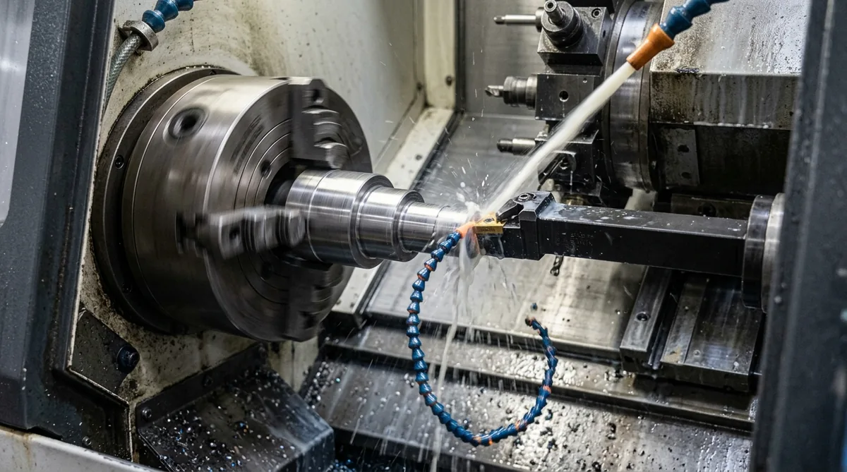
• Spindle Runout Control: Total Indicated Runout (TIR) held within 0.008 – 0.015 mm with critical journal diameters ground to ±0.005 mm.
• Chip Evacuation: Slanted bed design (30° to 45°) directs chips immediately into the conveyor, preventing workpiece scratching.
C-AXIS (Main Spindle Rotation)Up to 6,000 RPM
Constant Surface Speed (CSS) automatically recalculates spindle RPM as tool moves radially to ensure consistent surface cutting velocity (Vc), uniform chip load, and optimal tool life.
X-AXIS (Radial Cross Feed)Tolerance ±0.005 mm
Moves perpendicular to spindle centerline. Dictates outside diameters (OD), bore diameters (ID), stepped shoulders, and parting depths (0.001 mm optical scale).
Z-AXIS (Longitudinal Travel)Repeatability ±0.002 mm
Traverses parallel to spindle centerline. Controls component overall length, thread leads, axial retaining grooves, and precision chamfers via ground ball screws.
Tool Engagement & Surface IntegrityRa 0.4 – 1.6 μm
Single-point indexable carbide/CBN inserts cleanly shear material, eliminating chatter. Roundness (circularity), cylindricity, and concentricity validated ≤ 0.005 mm.
Multi-Axis Mill-Turn & Swiss-Type Turning
For intricate turned components requiring cross-milling, angled holes, or micro-diameters, AS Prototypes deploys advanced Swiss-type sliding headstocks and multi-axis mill-turn centers. For an engineering deep-dive into guide bushing kinematics and microscopic shaft concentricity, read our comprehensive guide on precision turning tolerances and Swiss lathe capabilities.
Swiss-Type Turning
Sliding Headstock
Deflection-free micro-machining for slender pins and shafts with length-to-diameter ratio L/D > 10:1.
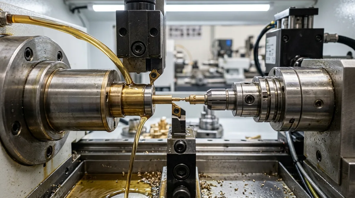
• Guide Bushing Support: Bar stock feeds through a carbide guide bushing where cutters engage within 1-2 mm, eliminating deflection.
• Slender Ratio Mastery: Machines ultra-long shafts with L/D up to 30:1 without requiring center rests or tailstocks.
• Micro Bar Capacity: Handles bar stock from Ø0.4 mm up to 32 mm with precision tolerances down to ±0.005 mm.
• Multi-Tool Gang Tooling: Up to 30 gang-mounted cutters and live spindles perform simultaneous turning and thread whirling.
Multi-Axis Mill-Turn
Live Tooling & Sub-Spindle
Simultaneous turning and 5-axis milling with B-axis tilting spindle and dual sub-spindle hand-off.
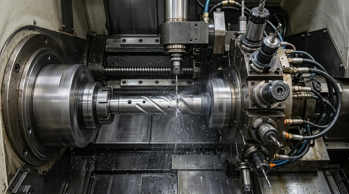
• Done-In-One Multi-Tasking: Integrates full lathe turning and multi-axis milling in one setup, eliminating secondary operations.
• Sub-Spindle Automatic Transfer: Synchronized sub-spindle picks off the part for seamless backside machining.
• Zero Tolerance Stacking: Eliminates fixture re-clamping, preserving datum alignment and concentricity within Ø0.008 mm (TIR ≤ 0.008 mm).
• Complex Geometry Freedom: Enables off-center drilling, helical splines, angled ports, and 3D pocketing on turned shafts.
Core CNC Turning Operations Guide
Our CNC turning centers execute standard and specialized lathe operations conforming to general tolerances ISO 2768-mK, with critical diameters, bearing journals, and ground pin shafts held to custom drawing tolerances down to ±0.005 mm:
1. Straight & Step TurningOD Profile
Uniform cylindrical diameter reduction and multi-step shoulder machining on rotating bar stock.
Tooling: CNMG, WNMG (Roughing) / CCGT, VBMT (Finishing) • Accuracy: ±0.005 mm (Precision Finishing)
2. Taper & Contour Turning2D/3D Profiles
CNC circular & linear interpolation generating precise conical tapers and complex curved radii.
Tooling: VBMT, DCMT • Angular: ±0.05° (Ra 0.8 μm)
3. Precision Grooving & CutoffRecesses
Narrow-blade plunging for O-ring channels, circlip retaining grooves, and clean cutoff.
Tooling: Carbide Cutoff Blades • Width: ±0.01 mm
4. External & Internal ThreadingThread Sync
Single-point spindle-synchronized thread tracking for custom Metric, UNC/UNF, ACME, and NPT.
Tooling: Thread Inserts • Accuracy: ISO 6g/6H
5. Diamond & Straight KnurlingGrip Texture
Forms or cuts textured diamond or straight serrations for positive hand grip or press-fit splines.
Tooling: Knurling Wheels • Pitch: 0.5 – 2.0 mm
6. Internal Boring & ReamingID Bores
Enlarges and trues drilled cavities with anti-vibration carbide boring bars for high-precision bearing bores.
Tooling: Solid Carbide Bars • Tolerance: ±0.005 mm
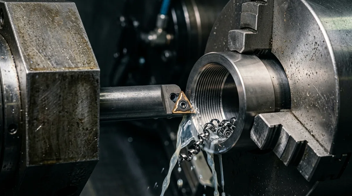
Anti-Vibration Boring Bar & Single-Point Thread Toolpath
Bore Truing & Internal Single-Point Threading
To eliminate taper and chatter across deep internal bores (depth-to-diameter ratio L/D up to 6:1), AS Prototypes utilizes heavy-metal and through-coolant carbide boring bars. Single-point threading cycles guarantee concentricity between external bearing diameters and internal retaining threads.
Best for: Hydraulic cylinder bodies, bearing hubs, transmission sleeves, and optical sensor mounts.
Precision CNC Turning Materials & Industrial Applications
Engineering Metals & Plastics Spectrum
We maintain a comprehensive raw inventory of prime-grade mill-spec bar stock ready for immediate lathe turning:
• Precision Metals: Aerospace Aluminum (6061-T6, 7075-T6, 2024), Stainless Steels (303, 304, 316L, 17-4PH), Titanium (Grade 2, Grade 5 / Ti-6Al-4V), Alloy Steels (4140, 1018, 12L14), Brass (C360), Bronze, and Copper.
• Engineering Plastics: PEEK, POM (Delrin / Acetal), PTFE (Teflon), Nylon (PA6/PA66), Ultem (PEI), and Polycarbonate (PC).
• Dimensional Capacity: Turned diameters from Ø0.4 mm up to Ø350 mm; max shaft length up to 600 mm.
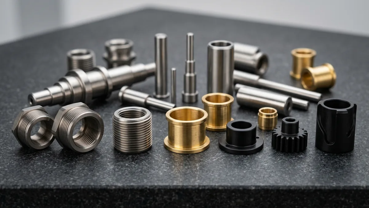
Typical Turned Components
• High-speed motor shafts, planetary pinions, and stepped spindles
• Hydraulic spool valves, manifold poppets, and high-pressure fluid fittings
• Medical bone screw prototypes, orthopedic implants, and cannula connectors
• Optical camera barrels, RF coaxial housings, and sensor sleeves
• Precision flanged bushings, alignment dowels, and custom threaded fasteners
Frequently Asked Questions (FAQ) About CNC Turning
What machining tolerances can AS Prototypes hold for CNC turned parts?
Our standard CNC turning conforms to ISO 2768-mK. For critical features, precision bearing journals, and ground pin shafts, our CNC lathes and Swiss machines hold tight tolerances down to ±0.005 mm (±0.0002″) in metals and ISO 2768-m in engineering plastics. Critical dimensions can be verified upon request in our metrology lab using Zeiss CMM touch probes, optical comparators, and air gages.
What is the difference between conventional CNC turning and Swiss-type turning?
In conventional CNC turning, bar stock is clamped rigidly in a chuck while cutting tools move along the part, making parts with length-to-diameter ratios exceeding 3:1 prone to deflection. Swiss-type turning utilizes a sliding headstock that feeds the bar through a rigid guide bushing, with cutting tools engaging within 1 mm of the support. This enables deflection-free machining of ultra-slender shafts (L/D up to 30:1) and miniature micro-components down to Ø0.4 mm.
What engineering materials are supported for custom CNC turned prototypes and production?
We stock and turn over 50 engineering-grade metals and plastics, including aluminum alloys (6061-T6, 7075-T6, 2024), stainless steels (303, 304, 316L, 17-4 PH), titanium (Ti-6Al-4V Grade 5), tool steels (4140, 12L14), brass (C360), bronze, copper, and engineering polymers such as PEEK, POM (Delrin), PTFE, Nylon, and Ultem.
What is the typical turnaround time and how do I receive an RFQ quote?
Rapid mechanical turned prototypes can be machined, deburred, and shipped in 4 to 8 business days (7 to 12 business days for parts requiring anodizing, passivation, or plating). Low-to-medium production batches (100 to 10,000+ pieces) typically complete ex-factory inspection in 7 to 25 business days (with international express air transit of 3 to 5 business days). Upload your 3D CAD files (STEP/IGES) along with 2D PDF drawings to our RFQ portal for an engineering review and quotation within 24 hours.
Need High-Precision Custom CNC Turned Parts?
At AS Prototypes, our CNC turning centers and live-tooling Swiss lathes deliver concentric, tight-tolerance cylindrical components with accuracy down to ±0.005 mm and fine surface finishes down to Ra 0.4 μm. Upload your 3D CAD models (STEP/IGES) for a free DFM review and guaranteed quotation within 24 hours.
🔒 Strict NDA Confidentiality • ISO 2768 Standard Tolerances • Zeiss CMM Inspection (Available Upon Request)