PRECISION 5-AXIS CNC MACHINING • SIMULTANEOUS & 3+2 • MULTI-AXIS MACHINING

5-Axis CNC Machining Services: Precision Multi-Axis Manufacturing

In-House 5-Axis
General Tolerance: ISO 2768-mK | Critical Tolerances to ±0.008 mm
Continuous Simultaneous & 3+2 Indexed
Complex Organic Geometries
Zeiss CMM Metrology (Upon Request)
Rapid Turnaround: 4–8 Days
In modern precision manufacturing, 5-axis CNC machining represents the pinnacle of multi-axis subtractive technology. By synchronizing cutting tool orientation across five continuous or indexed axes, our engineering team sculpts organic contours, deep internal cavities, and tight-tolerance prismatic features in a single setup. At AS Prototypes, our in-house multi-axis machining facility empowers aerospace, medical device, robotics, and high-tech developers to achieve superior surface finishes, eliminate cumulative fixture stack-up error, and accelerate time-to-market.

1. What Is 5-Axis CNC Machining & How It Works

Five-axis machining is an advanced subtractive manufacturing process that enables a cutting tool or workpiece to maneuver across five distinct degrees of freedom simultaneously. In addition to conventional linear movements along the X, Y, and Z orthogonal axes, the machine incorporates two rotational axes selected from A, B, or C.

This spatial dexterity allows the milling spindle to approach the raw stock from virtually any compound angle in a single setup. By eliminating repetitive manual re-clamping characteristic of 3-axis operations, 5-axis CNC machining eradicates stack-up tolerance deviations, dramatically minimizes cycle times, and delivers unmatched geometric fidelity on sculptured aerospace and medical components.
AS Prototypes Engineering Protocol: Every multi-axis program originates from precise 3D CAD modeling (STEP/IGES), translated via industry-grade CAM platforms with full machine kinematics verification and dynamic collision envelope simulation to eliminate collision hazards before physical cutting commences.
Kinematic RTCP / TCPM Vector Control: Our continuous 5-axis centers utilize Rotational Tool Center Point (RTCP) and Tool Center Point Management (TCPM) interpolation. The CNC controller automatically recalculates linear axis offsets in real time as rotary axes tilt, maintaining precise cutter contact points without G-code recalculation and eliminating gouging on deep contoured impellers.
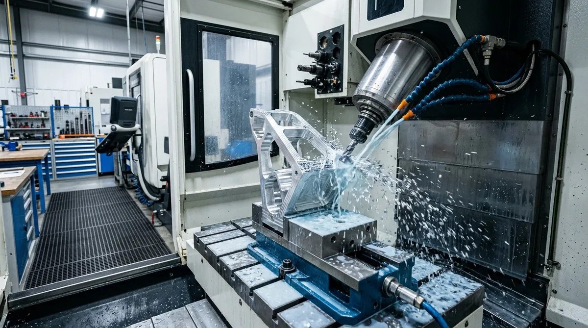
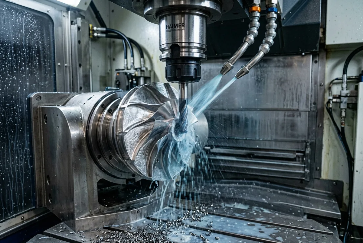
Simultaneous 5-Axis CNC Trunnion Machining Center Milling Aerospace Aluminum Bracket

Figure 1: High-precision 5-axis trunnion machining center milling a complex aluminum structural component with flood coolant.

2. What Does the “5” in 5-Axis Stand For? (Kinematic Coordinates)
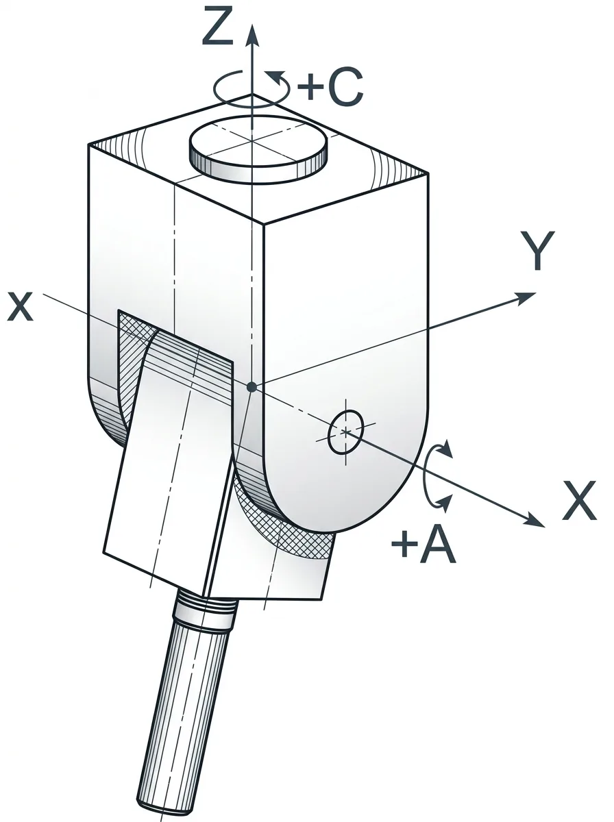
5-Axis CNC Swivel Spindle Kinematics and Rotational Axes Diagram

Figure 2: Articulating swivel head coordinate system illustrating A-axis tilt and C-axis rotation relative to linear Cartesian axes.
The designation “5” refers to the five coordinate axes along which relative motion occurs between the cutting tool and the workpiece. While traditional 3-axis CNC mills move exclusively across linear Cartesian planes, 5-axis machines superimpose two rotational degrees of freedom:
X-Axis:Primary horizontal travel (Left / Right)

Linear

Y-Axis:Secondary horizontal travel (Forward / Backward)

Linear

Z-Axis:Vertical travel (Up / Down, aligned with spindle axis)

Linear

A-Axis:Angular rotation around the X-axis (Pitch / Tilt)

Rotational ±110°

B- or C-Axis:Rotation around Y-axis (B-tilt) or Z-axis (C-continuous)

Rotational 360°

By continually aligning the cutter perpendicular to complex curved surfaces, the machine employs shorter, more rigid end mills, drastically suppressing tool vibration and generating glass-smooth surface finishes down to Ra 0.4 μm.

3. Core Configurations of 5-Axis CNC Machines
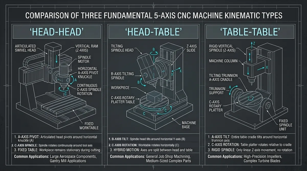
5-axis CNC machines are engineered in three primary kinematic architectures based on whether the two rotary axes reside in the spindle head, the worktable, or a hybrid combination:
Three Fundamental 5-Axis CNC Machine Kinematic Types Comparison

Figure 3: Kinematic comparison across Head-Head, Head-Table, and Table-Table (Trunnion) 5-axis machine platforms.
CONFIGURATION 1

Head-Head Configuration

Both rotary axes (A & C) are built into the spindle head. The workpiece remains rigidly clamped to a stationary, vibration-damped machine bed while the articulating head maneuvers freely around the perimeter.
CONFIGURATION 2

Head-Table (Hybrid)

Features one rotary axis in the spindle head (B-tilt) and one rotary axis in the table (C-rotary platter). This kinematic distribution delivers unrestricted 360-degree rotational indexing while maintaining superior stiffness.
CONFIGURATION 3

Table-Table (Trunnion)

Both rotary axes (A & C or B & C) are integrated into a rigid tilting cradle table. The vertical spindle focuses solely on high-speed linear XYZ cutting, yielding the tightest positional repeatability.

4. Continuous 5-Axis (Simultaneous) vs. 3+2 Positional Machining (Indexed)

A crucial engineering distinction in multi-axis manufacturing lies between Continuous Simultaneous 5-Axis and 3+2 Indexed Positional machining:

In Continuous 5-Axis Machining, all five axes move harmoniously and concurrently throughout the cutting cycle. This allows the cutter to sweep across fluid, organic 3D contours without stopping, indispensable for turbine blades, aerospace impellers, and patient-specific medical implants.

In 3+2 Indexed Machining, the machine utilizes two rotary axes to tilt and lock the workpiece at an optimal spatial orientation, after which standard 3-axis milling takes place. This approach provides rapid access to five faces of a prismatic part in a single clamping, dramatically slashing fixture fabrication costs.
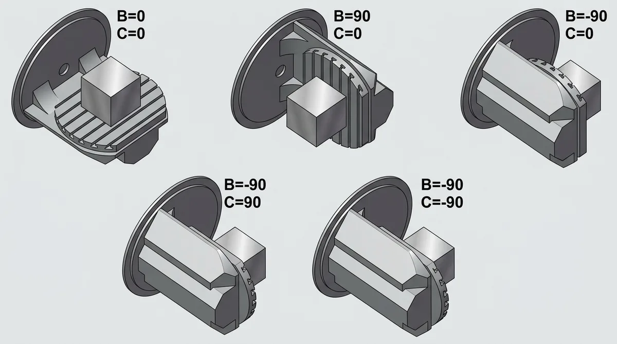
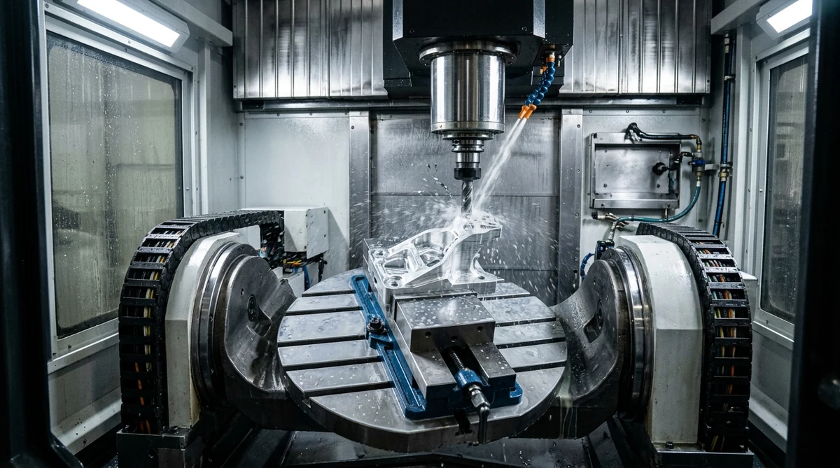
3+2 Positional 5-Axis CNC Multi-Face Indexing on Rotary Table

Figure 4: Single-setup multi-face indexing on a 5-axis rotary trunnion table eliminating re-clamping positional drift.
Machining CategoryTool KinematicsAchievable ToleranceSetup EfficiencyOptimal Applications
Continuous 5-Axis (Simultaneous)X, Y, Z, A, B/C axes engage concurrently during cutting±0.008 mm ~ ±0.015 mm100% Single-setup (Zero re-clamping error)Turbine blisks, organic impellers, contoured aero-surfaces
3+2 Positional (Indexed 5-Axis)Workpiece tilted and locked at compound angle; linear cutting±0.012 mm ~ ±0.020 mm1–2 setups (Saves 70% custom fixture fabrication)Multi-sided prismatic chassis, deep cavities, angled cross-holes
Conventional 3-Axis CNCLinear X, Y, Z motion only; tool fixed vertically±0.020 mm ~ ±0.050 mm3–5 setups required for multi-sided geometries2.5D planar plates, planar brackets, straightforward enclosures

5. Manufacturing Advantages: Single-Setup Precision & Geometric Freedom

01. ±0.008 mm POSITIONAL ACCURACY

Single-Setup Eliminates Datum Drift & Stack-Up Error

Machining up to five faces without re-clamping eradicates datum shift and manual operator alignment error, securing extreme GD&T true position tolerances.
02. SHORT, RIGID CUTTING TOOLS

Superior Surface Finish (Ra 0.4–0.8 μm)

By tilting the tool orientation, stubby end mills access deep pockets without excessive overhang. Minimized chatter yields pristine surfaces and longer tool life.
03. COMPLEX SCULPTURED GEOMETRIES

Unlimited Design Freedom

Realizes compound organic sweeps, complex aero undercuts, and conformal fluid cooling channels that cannot be physically produced on 3-axis machinery.
04. 70% FIXTURE COST REDUCTION

Universal Modular Workholding

Multi-angle accessibility avoids designing complex custom secondary fixtures for each rotated face, significantly trimming initial NRE tooling investments.
05. HIGH-SPEED MACHINING (HSM)

Dynamic Spindle & Fast Chip Evacuation

Continuous rotation allows constant tool engagement at optimal surface speeds, maximizing material removal rates (MRR) on titanium and aluminum billets.
06. FAST-TRACK RAPID PROTOTYPING

Ex-Factory Turnaround in 4–8 Business Days

Compressed setup cycles mean functional metal and engineering plastic prototypes go from 3D CAD to CMM-verified parts on your test bench in days, not weeks.

6. Overcoming 5-Axis Engineering Challenges: AS Prototypes Capabilities

While 5-axis CNC machining delivers extraordinary precision, it introduces significant technical hurdles including kinematic collision hazards, intricate post-processing, and thermal drift. Here is how AS Prototypes solves these challenges:

Challenge: Complex Multi-Axis CAM Programming & Collision Risks

Our Solution: Our engineering team boasts over a decade of dedicated 5-axis CAM programming experience. Every multi-axis toolpath is subjected to 100% digital kinematic simulation and dynamic collision envelope verification using high-end verification suites (such as ModuleWorks and Vericut), completely preventing spindle-fixture collisions and gouging.

Challenge: Higher Machine Hourly Rates & Upfront Setup Costs

Our Solution: We implement standardized modular zero-point clamping systems and standardized quick-change tooling. This reduces setup changeovers from hours to under 15 minutes, enabling us to offer competitive prototype pricing and lower part costs for low-volume production batches.

Challenge: Multi-Axis Thermal Expansion & Positional Accuracy Drift

Our Solution: Our 5-axis machining shop operates in a 24/7 temperature-regulated environment (±1°C). Combined with spindle chillers, laser tool setters, Renishaw on-machine touch probes, and final inspection on our high-precision Zeiss CMM, we routinely validate critical dimensional tolerances compliant with ISO 2768-fH (±0.008 mm).

7. High-Precision Components & Compatible Engineering Materials
5-Axis Simultaneous CNC Machined Titanium Impeller Blisk with Aerodynamic Curved Blades

Complex Organic Surfaces

Turbine blades, aerospace impellers, fluid mixing augers, and contoured aerodynamic shells.
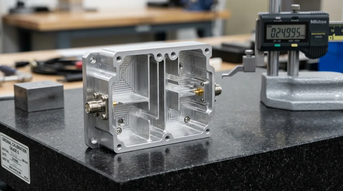
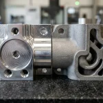
Precision 5-Axis CNC Machined 6061-T6 Aluminum RF Filter Cavity Enclosure on Granite Surface Plate with Mitutoyo Digimatic Height Gauge

Multi-Sided Prismatic Enclosures

Avionics gearboxes, robotic arm knuckles, RF filter cavity housings, and optical sensor chassis.
5-Axis CNC Machined Aerospace Structural Bracket

Precision Structural Brackets

Aerospace bulkheads, titanium bone fixation plates, surgical guides, and optical mirror gimbals.
Compatible Engineering Alloys & High-Performance Polymers:
  • Aluminum Alloys: 6061-T6, 7075-T651 (high-strength aircraft grade), 2024, 5083.
  • Titanium & Superalloys: Ti-6Al-4V (Grade 5), Grade 2 pure titanium, Inconel 718.
  • Stainless & Tool Steels: 316L (medical grade), 304, 17-4PH precipitation hardened, 4140, D2.
  • High-Performance Polymers: PEEK (implant grade / carbon-fiber filled), POM-C (Delrin), PTFE (Teflon), Nylon 6/66, Ultem PEI.
Explore complementary machining processes: Precision CNC Milling Services & Comprehensive CNC Machining Solutions.

8. Demanding Industry Applications & Quality Compliance

Aerospace & Defense →

Turbine blades, fuel manifolds, lightened satellite brackets, and flight control linkages.

Medical Devices & Implants →

Titanium orthopedic bone plates, cranial implants, robotic surgical end-effectors, and MRI housings.

Robotics & Automation →

Harmonic drive housings, multi-axis robotic wrists, AGV steering knuckles, and zero-backlash couplings.

Electronics & Telecom →

RF cavity wave-guide filters, semiconductor test fixtures, and custom liquid-cooling cold plates.

9. Frequently Asked Questions (5-Axis Machining FAQs)

What standard tolerances can AS Prototypes achieve on continuous 5-axis CNC machining?
Our continuous 5-axis machining centers routinely deliver general tolerances compliant with ISO 2768-mK. For critical dimensional features such as bearing bores, locating pin holes, and precision mating surfaces, our engineering team reliably holds tight tolerances down to ±0.008 mm (ISO 2768-fH) verified via on-site Zeiss CMM inspection.
What is the practical difference between simultaneous 5-axis and 3+2 indexed machining?
Simultaneous continuous 5-axis machining coordinates all 3 linear and 2 rotational axes simultaneously during cutting, which is mandatory for fluid organic curves (e.g. impellers and turbine blades). In contrast, 3+2 indexed machining positions and locks the workpiece at compound angles to machine multiple prismatic flat faces with rigid 3-axis tool movements, significantly cutting fixture fabrication costs.
What 3D CAD formats are accepted for an instant 5-axis CNC quote?
We accept standard 3D CAD file formats including STEP (.stp, .step), IGES (.igs), and Parasolid (.x_t). If your components feature tight precision tolerances, threaded holes, or surface roughness specifications, please also upload a 2D engineering drawing in PDF format with GD&T callouts.
How does AS Prototypes verify parts quality before shipment?
Every production run undergoes strict in-process inspection and final quality assurance. Our quality control lab utilizes a high-precision Zeiss CMM (Coordinate Measuring Machine), optical profile projectors, surface roughness profilometers, and thread plug gauges. Full-dimensional First Article Inspection Reports (FAIR) and Mill Test Reports (MTR) are provided upon request.

Ready to Precision-Machine Your 5-Axis Components?

Upload your 3D CAD files today for a confidential DFM review and competitive quotation within 24 hours. From complex one-off prototypes to scalable low-volume batches, AS Prototypes delivers multi-axis precision.
🔒 Strict NDA Confidentiality
● ISO 2768 Standard Tolerances
✓ In-House Zeiss CMM Inspection (Available Upon Request)

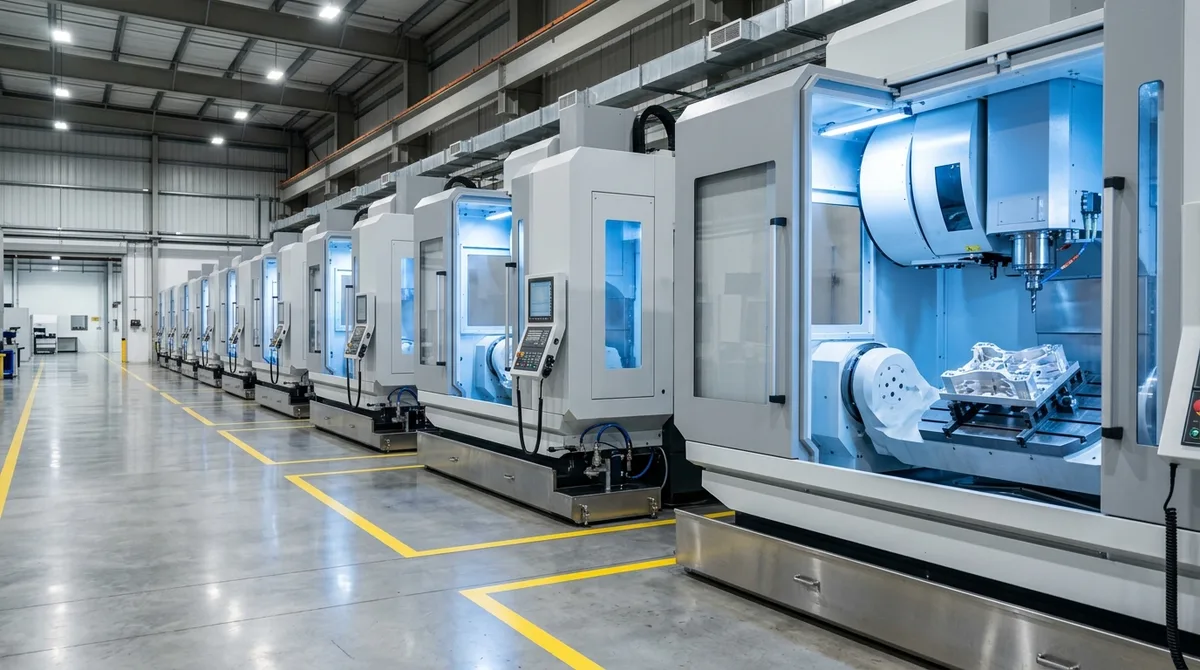
Advanced In-House 5-Axis Simultaneous CNC Machining Centers Fleet in Shenzhen Facility

AS Prototypes in-house multi-axis machining center fleet delivering rapid turnaround for precision aerospace, medical, and industrial components.

⚡ Upload CAD & Get a 24h Quote →