Precision Grinding Services: Surface, Cylindrical & Centerless
Core Precision Grinding Capabilities & Process Types
At AS Prototypes, our grinding department operates in temperature-controlled environments to eliminate thermal expansion during abrasive machining. We utilize vitrified alumina, CBN (Cubic Boron Nitride), and diamond abrasive wheels tailored to specific workpiece metallurgical properties.
1. Precision CNC Surface Grinding
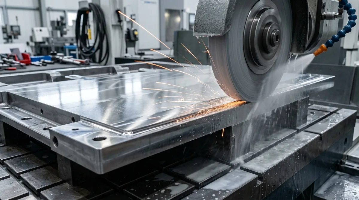
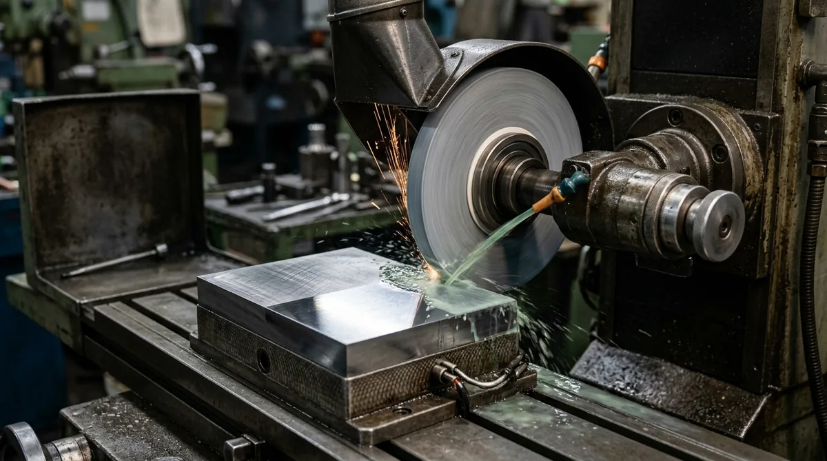
Surface grinding produces high-precision planar geometry, exceptional flatness, and parallelism across metallic and non-metallic workpieces. Utilizing high-rigidity horizontal and vertical spindle surface grinders equipped with electro-permanent magnetic chucks, we control micro-downfeed increments down to 0.005 mm per pass.
- Primary Geometry: Flat plates, precision guide rails, mold base plates, shim spacers, shear blades.
- Maximum Envelope: Up to 1,000 × 500 × 400 mm.
- Key GD&T Controls: Flatness ≤ 0.005 mm / 100 mm; Parallelism ≤ 0.005 mm.
2. External Diameter (OD) Cylindrical Grinding
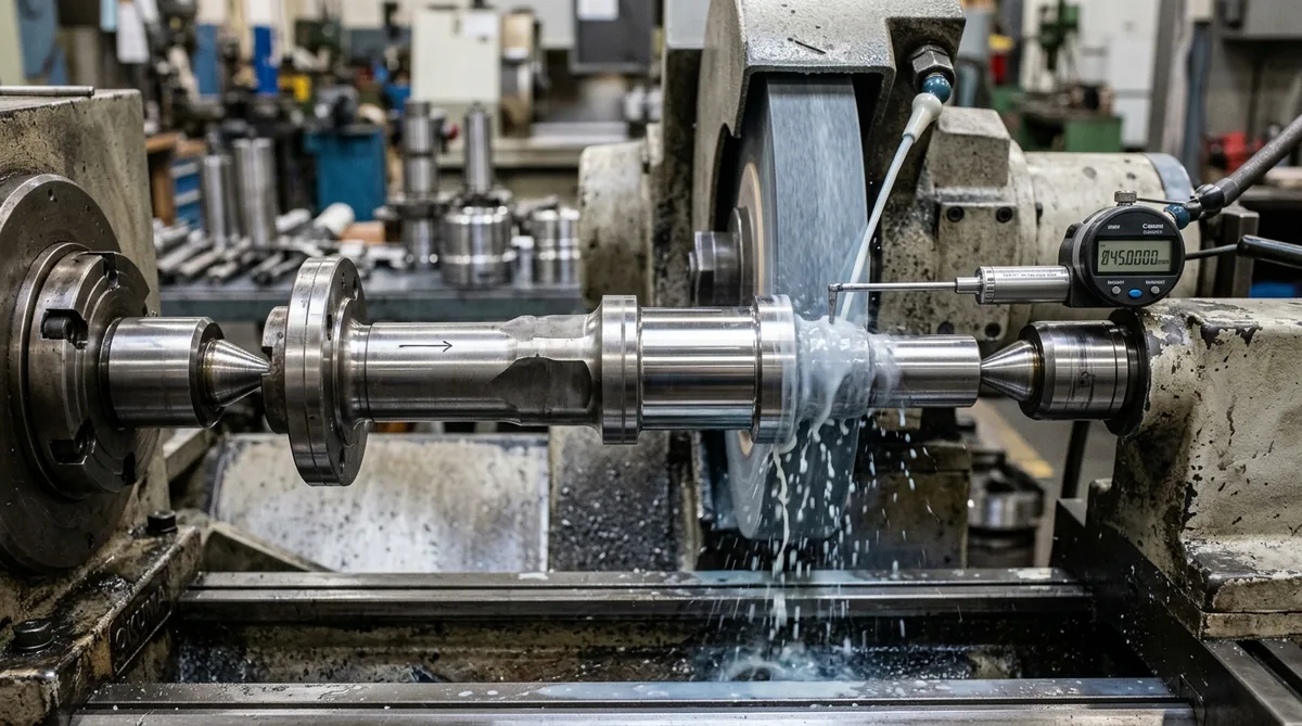
For rotational components, between-centers and chucked cylindrical OD grinding guarantees stringent concentricity, roundness, and runout. Integrated with in-process optical gauging and hydrostatic spindle bearings, our universal cylindrical grinders achieve mirror finishes on multi-stepped shafts and high-pressure hydraulic spools.
- Primary Geometry: Precision motor shafts, turbine rotors, transmission shafts, valve pistons, eccentric pins.
- Maximum Envelope: Diameter up to Ø320 mm; Length up to 1,000 mm between centers.
- Key GD&T Controls: Roundness ≤ 0.003 mm; Total Radial Runout ≤ 0.005 mm.
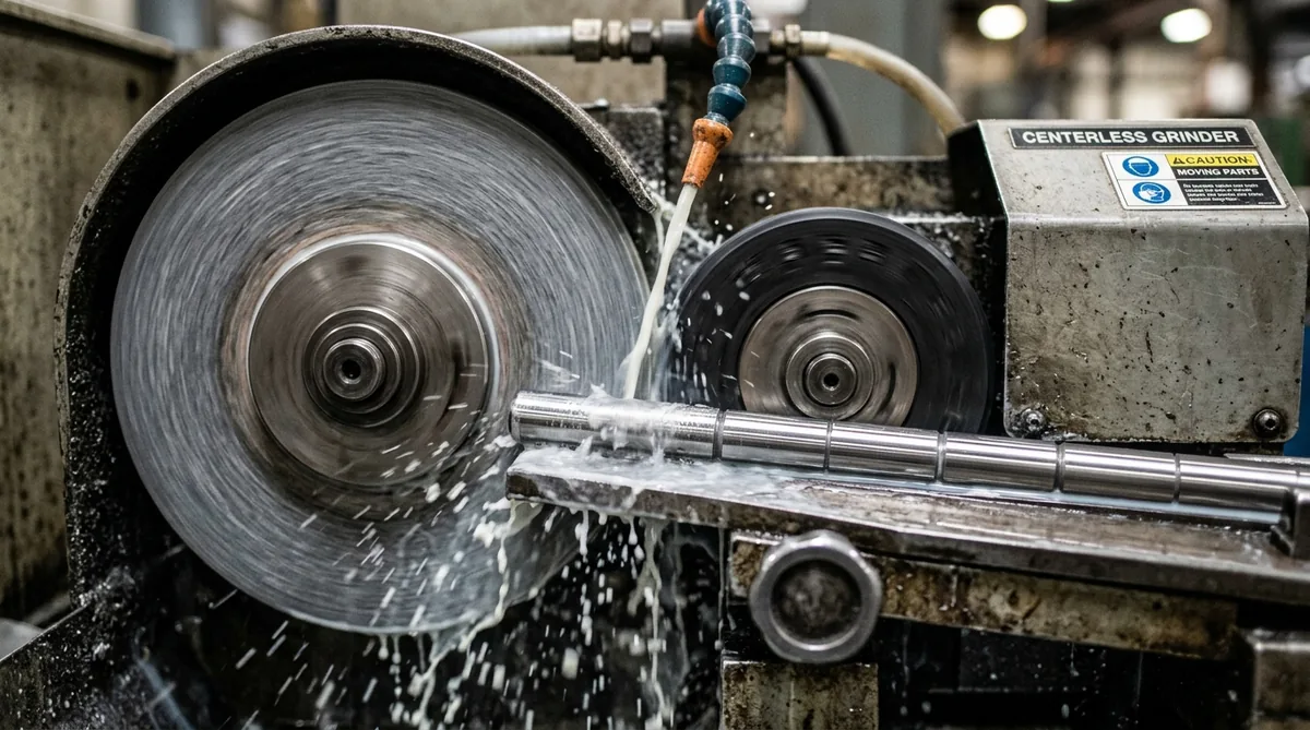
3. High-Throughput Centerless Grinding
Centerless grinding is the premier solution for rapid, cost-effective finishing of cylindrical pins, rods, and needles without the need for center holes or chucking fixtures. Supported by a carbide work-rest blade and regulated by a rubber-bonded regulating wheel, we offer both Through-Feed (for continuous straight shafts) and In-Feed / Plunge (for stepped, profiled, or headed pins).
- Primary Geometry: Medical guide pins, automotive needle rollers, dowel pins, hydraulic spool stems.
- Diameter Range:Ø0.5 mm to Ø60 mm; Part lengths up to 3,000 mm (through-feed).
- Key GD&T Controls: Roundness ≤ 0.003 mm; Diameter consistency ±0.005 mm across high volumes.
4. Internal Diameter (ID) Grinding
Internal grinding finishes the inside diameter of precision bores, bushing sleeves, and hardened rings. Utilizing ultra-high-frequency electric quills spinning up to 90,000 RPM with specialized micro-CBN abrasive quills, AS Prototypes prevents bell-mouthing and taper errors in deep internal bores.
- Geometry: Bearing race inner bores, hydraulic cartridge sleeves, collet chuck bodies, cylinder liners.
- Machining Range: Bore Ø3.0 mm to Ø200 mm; Grinding depth up to 250 mm.
- Key GD&T: Cylindricity ≤ 0.004 mm; Perpendicularity to face ≤ 0.005 mm.
5. Optical CNC Jig & Coordinate Grinding
For progressive stamping dies, high-precision gauge plates, and complex fixtures, coordinate jig grinding provides hole position accuracy down to ±0.005 mm after final heat treatment. Planetary grinding heads equipped with glass scale linear encoders ensure pitch and center distance accuracy that conventional machining centers cannot match.
- Geometry: Stamping die retainer plates, master inspection fixtures, precision punch guides.
- Envelope: 650 × 450 × 300 mm.
- Key GD&T: True Hole Position ≤ 0.005 mm; Pitch Distance Accuracy ±0.005 mm.
Precision Grinding Tolerances & Technical Specifications
| Grinding Process | Max Workpiece Envelope | Dimensional Tolerance | Geometric Tolerance (GD&T) | Surface Finish (Ra) | Typical Tooling & Applications |
|---|---|---|---|---|---|
| Surface Grinding | 1,000 × 500 × 400 mm | ±0.005 mm (±0.0002″) | Flatness & Parallelism ≤ 0.005 mm / 100 mm | Ra 0.1 ~ 0.4 μm | Hardened mold plates, machine way guides, gauge blocks, stamping dies |
| Cylindrical OD Grinding | Ø320 mm × 1,000 mm L | ±0.005 mm (±0.0002″) | Roundness & Runout ≤ 0.003 mm | Ra 0.05 ~ 0.2 μm (Mirror) | High-speed motor shafts, turbine rotors, hydraulic spool valves, pinions |
| Internal ID Grinding | Ø3.0 ~ Ø200 mm × 250 mm D | ±0.005 mm (±0.0002″) | Cylindricity ≤ 0.004 mm | Ra 0.1 ~ 0.3 μm | Bearing inner rings, hardened bushing bores, sleeve liners, fuel injection nozzles |
| Centerless Grinding | Ø0.5 ~ Ø60 mm × 3,000 mm L | ±0.005 mm (±0.0002″) | Roundness ≤ 0.003 mm | Ra 0.1 ~ 0.3 μm | Medical guide pins, precision rollers, automotive needle bearings, valve lifters |
| Jig / Coordinate Grinding | 650 × 450 × 300 mm | ±0.005 mm (±0.0002″) | True Hole Position ≤ 0.005 mm | Ra 0.1 ~ 0.2 μm | Progressive stamping die plates, transfer tooling, master jig fixtures |
Materials & Hardness Spectrum: Tool Steels to Tungsten Carbide
Precision grinding excels where traditional cutting tools fail due to extreme material hardness, abrasive characteristics, or severe cutter wear. AS Prototypes processes a comprehensive range of pre-hardened steels, superalloys, and non-metallic substrates:
Wheel Type: CBN (Cubic Boron Nitride) or high-purity vitrified white alumina with synthetic flood coolant.
Applications: Surgical instruments, pump shafts, marine valves. Low downfeed pressure prevents work hardening.
Wheel Type: Metal-bonded and resin-bonded diamond abrasive wheels with micro-dressing.
Applications: Hydraulic cylinder rods, aerospace landing gear actuators, printing rolls.
Metrology & Quality Assurance: High-Precision Verification Down to ±0.005 mm
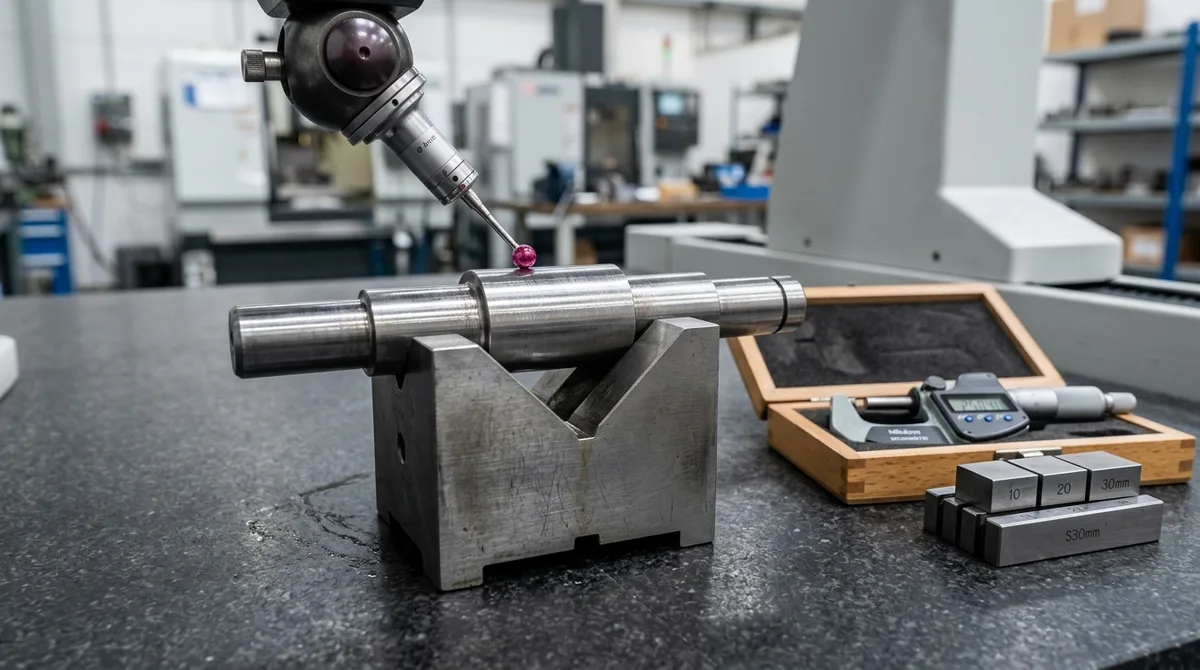
Sub-micron precision manufacturing is meaningless without rigorous, traceable inspection. In our dedicated climate-controlled quality laboratory (maintained at 20 ± 0.5°C), every ground dimension and surface characteristic is verified using state-of-the-art metrology equipment:
- Zeiss Coordinate Measuring Machine (CMM) (Available Upon Request): Continuous contact scanning probes verify complex 3D profiles, hole pitch distances, flatness, parallelism, and true position down to ±0.005 mm accuracy.
- High-Precision Roundness Metrology: Dedicated spindle roundness and cylindricity testers detect micro-undulations, runout, and lobing on cylindrical shafts.
- Surface Profilometers (Stylus & Optical): Quantitative Ra, Rz, Rmax roughness profiling ensures that dynamic seal journals meet precise lubrication and wear criteria.
- FAIR Documentation: Full dimensional reports, material traceability records, and CMM inspection data supplied with every production batch (available upon request).
Engineering DFM Guidelines for Precision Grinding
Incorporating grinding-specific Design for Manufacturability (DFM) features during the CAD design phase eliminates manufacturing bottlenecks, prevents wheel edge chipping, and significantly reduces machining costs:
Industry Solutions: Where High-Precision Grinding Is Essential
Frequently Asked Questions (FAQ)
Q1: What dimensional tolerances and surface finishes can AS Prototypes achieve with precision grinding?
Q2: When should I choose precision grinding over CNC hard milling or wire EDM?
Q3: Can you grind parts that have already undergone heat treatment?
Q4: What are your maximum workpiece dimensions for surface and cylindrical grinding?
Q5: How do I submit an RFQ for precision grinding, and what files are required?
Need High-Precision Grinding & Mirror Finishes?
Equipped with CNC surface grinders, universal cylindrical OD/ID grinders, and centerless grinding cells, AS Prototypes guarantees tolerances down to ±0.005 mm (±0.0002″) and surface roughness down to Ra 0.05 μm. From one-off hardened tool steel prototype dies to mass-produced precision shaft pins, our engineering team provides rapid quoting within 24 hours, CMM metrology inspection reports, and fast global delivery.