Industrial 3D Printing Services: Metal, Resin & Plastic Parts
AS Prototypes provides industrial 3D printing services in our in-house additive facility: Stereolithography (SLA) resin, Selective Laser Sintering (SLS) and HP Multi Jet Fusion (MJF) nylon, Direct Metal Laser Sintering (DMLS), Fused Deposition Modeling (FDM) and Digital Light Processing (DLP). Typical as-printed accuracy is ±0.10–0.20 mm per 100 mm (±0.001–0.002 in per inch), with micro-detail DLP holding ±0.02–0.03 mm on small parts.
Quick Takeaways
- Pick the process by the requirement: SLA for cosmetic detail, SLS/MJF nylon for functional plastic parts, FDM for high-temp thermoplastics and fixtures, DMLS for end-use metal.
- Use datasheet numbers carefully: printed parts are anisotropic, so the Z-axis (build direction) is often weaker than XY.
- Tolerance grows with size: accuracy is stated per 100 mm, so a 200 mm part carries about twice the deviation of a 100 mm part.
- Every order starts with an engineer-reviewed quote: we perform a Design for Manufacturability (DFM) review of your CAD and reply within 24 hours.
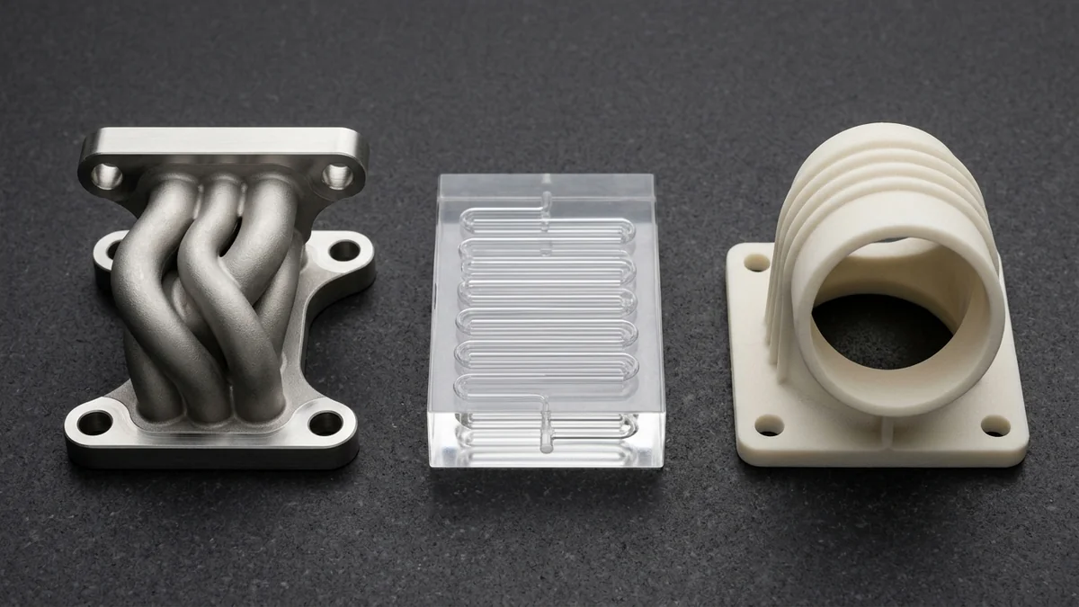
Core Industrial 3D Printing Technologies
Each process fuses material differently—as illustrated by the CNC-machined DMLS 316L manifold, clear SLA microfluidic block and SLS PA12 elbow duct above. Start with the part’s function, then match the process:
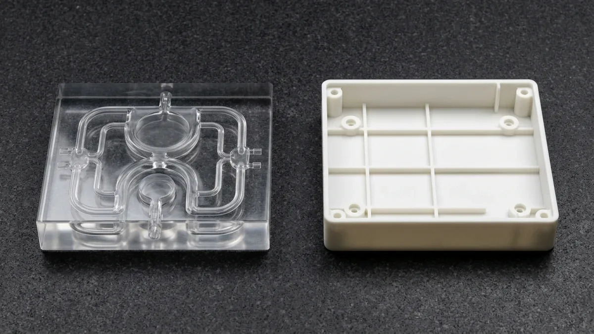 SLA · High-Detail Resin
SLA 3D Printing
Stereolithography (SLA) cures liquid photopolymer with a UV laser up to 800 × 800 × 550 mm (31.5 × 31.5 × 21.7 in). It gives the smoothest surface among our large-format processes (Ra 0.8–1.6 µm / 32–63 µin) and typical accuracy of ±0.20 mm per 100 mm. Best for cosmetic models, clear fluidic blocks and master patterns.
Learn More About SLA →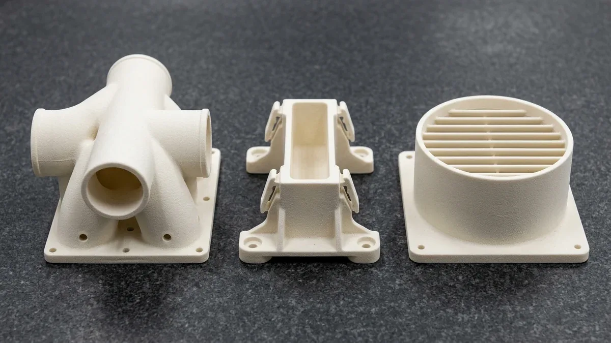 SLS · Functional Nylon
SLS 3D Printing
Selective Laser Sintering (SLS) fuses polyamide powder with a laser across a 400 × 400 × 450 mm (15.7 × 15.7 × 17.7 in) chamber. Surrounding powder supports the part, so internal manifolds, cantilever snap-fits and louvers print without support structures. Typical accuracy is ±0.20 mm per 100 mm.
Learn More About SLS →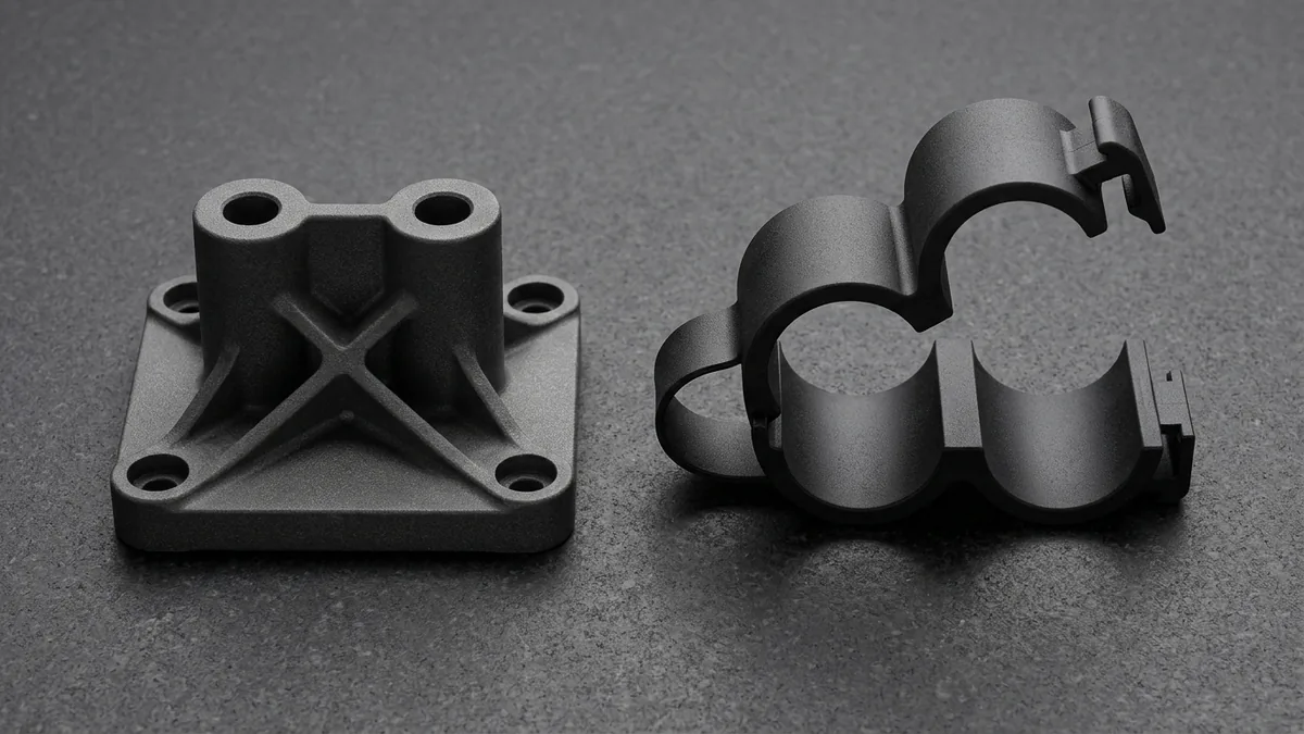 MJF · Dense Nylon
HP Multi Jet Fusion (MJF)
HP Multi Jet Fusion (MJF) jets fusing and detailing agents onto a 380 × 284 × 380 mm (15.0 × 11.2 × 15.0 in) powder bed, then fuses the layer with infrared energy. It produces dense, consistent PA12, PA11 and TPU nylon parts for clevis brackets, living-hinge clamps and small production runs.
Learn More About MJF →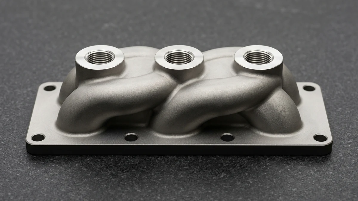 DMLS / SLM · Direct Metal
Metal 3D Printing (DMLS / SLM)
Direct Metal Laser Sintering (DMLS) melts spherical metal powder in a 280 × 280 × 365 mm (11.0 × 11.0 × 14.4 in) dual-laser chamber. We print Ti-6Al-4V, AlSi10Mg, 316L, 17-4PH, Inconel 718 and 18Ni300 maraging steel for lightweight brackets, hydraulic manifolds and conformal-cooling inserts.
Learn More About Metal Printing →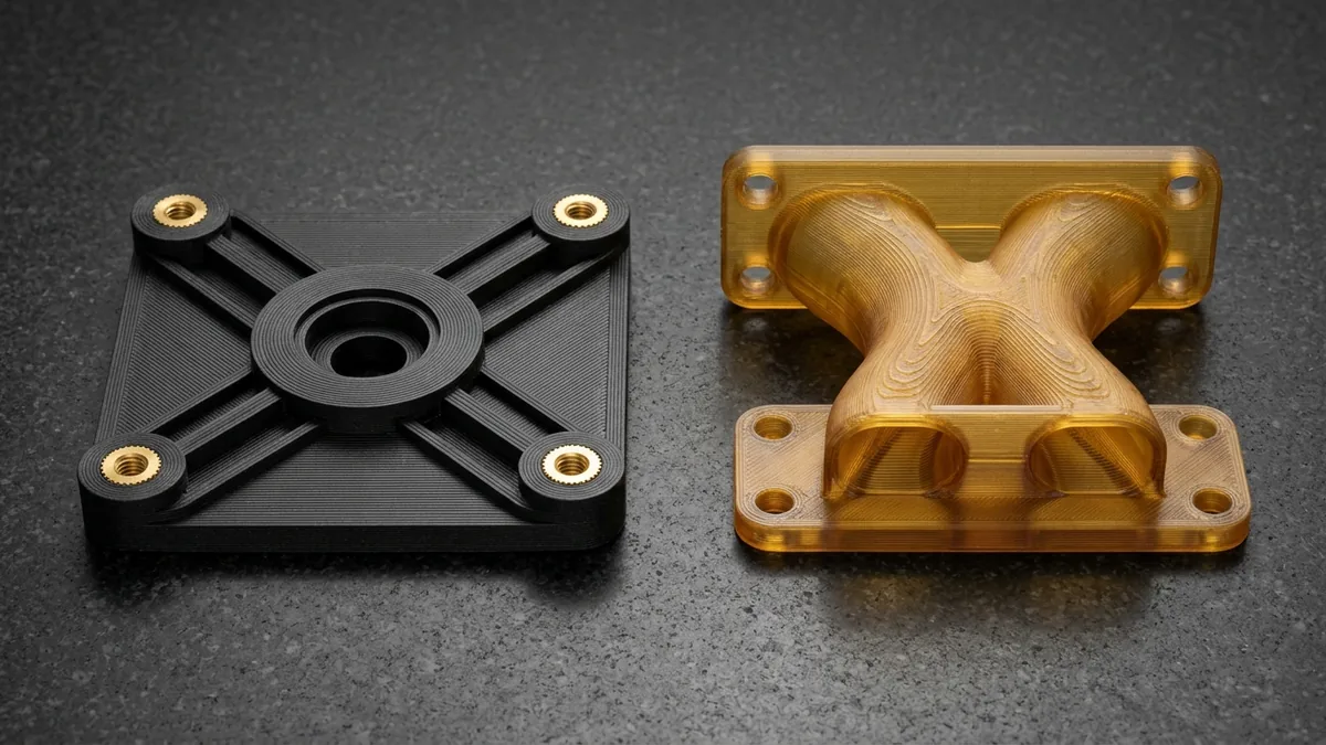 FDM · Thermoplastics
Industrial FDM 3D Printing
Fused Deposition Modeling (FDM) extrudes engineering thermoplastics—ABS-M30, ASA, PC-10, carbon-fiber nylon (PA12-CF), ULTEM 9085/1010 and PEEK. It suits functional builds up to 406 × 355 × 406 mm (16.0 × 14.0 × 16.0 in), motor plates, jigs and heat-resistant ducts.
Learn More About FDM →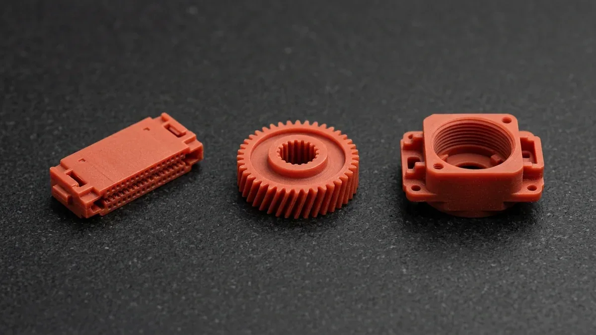 DLP · Micro-Detail
Micro-Nano DLP (Red Wax)
Digital Light Processing (DLP) uses a 4K projector engine and fine red-wax resin at 15–25 µm layers across 90 × 50 × 100 mm (or 192 × 108 × 200 mm at 50 µm). It reproduces micro-text, thin ribs and sharp edges for connectors, micro-gears and investment-casting patterns.
Learn More About DLP →3D Printing Process Comparison: Tolerance, Size & Best Use
These values are typical for our equipment. Tolerance is stated per 100 mm of part size, so larger parts carry proportionally larger deviation:
| Process | Typical Materials | Typical Tolerance | Max Single-Piece Build | As-Printed Surface | Recommended Application / When to Choose |
|---|---|---|---|---|---|
| SLA | Tough White/ABS-Like (Taurus), WaterShed XC 11122, PerFORM | ±0.20 mm per 100 mm | 800 × 800 × 550 mm (31.5 × 31.5 × 21.7 in) | Ra 0.8–1.6 µm (32–63 µin) | Cosmetic models, clear fluidics, smooth masters |
| SLS | PA12 (Nylon 12), PA12-GF (Glass-Filled), Flexible TPU | ±0.20 mm per 100 mm | 400 × 400 × 450 mm (15.7 × 15.7 × 17.7 in) | Ra 8–12 µm (315–472 µin), grainy matte | Snap-fits, hinges, ducts, support-free geometry |
| MJF | PA12 Nylon, PA11, PA12-GB (Glass Bead), Flexible TPU | ±0.15–0.20 mm per 100 mm | 380 × 284 × 380 mm (15.0 × 11.2 × 15.0 in) | Ra 6–10 µm (236–394 µin), charcoal matte | Repeatable small batches of functional nylon parts |
| FDM | ABS-M30, ASA, PC-10, PA12-CF, ULTEM 9085/1010, PEEK | ±0.20 mm or ±0.2%, whichever is greater | 406 × 355 × 406 mm (16.0 × 14.0 × 16.0 in) | Ra 10–25 µm (394–984 µin), visible layer lines | High-temp ducts, PA12-CF plates, shop jigs |
| DMLS / SLM | Ti-6Al-4V, AlSi10Mg, 316L, 17-4PH, Inconel 718, 18Ni300 | ±0.10 mm per 100 mm (±0.010–0.020 mm CNC post-machined) | 280 × 280 × 365 mm (11.0 × 11.0 × 14.4 in) | Ra 6–12 µm (236–472 µin), matte metallic | End-use metal, lightweighting, internal channels |
| 4K DLP (Red Wax) | Opaque Matte Red Wax (RCP30/MD1500-Equiv.), Castable Wax | ±0.02–0.03 mm | 90 × 50 × 100 mm (3.5 × 2.0 × 3.9 in) / 192 × 108 × 200 mm @ 50 µm | Ra 0.4–0.8 µm (16–32 µin) | Micro connectors, fine gears, casting patterns |
3D Printing Material Properties: Verified Datasheet Comparison
Every number below is compiled from the material manufacturer’s own technical data sheet (TDS), not from a reseller. Values are typical, not guaranteed minimums:
Read three things before comparing rows. First, test method: tensile data follows ISO 527 or ASTM D638. Second, orientation: XY lies in the build plane, Z is the build direction. Third, post-cure: UV-only and UV-plus-thermal resin cures give very different heat resistance. Imperial conversions: 1 ksi = 6.895 MPa; °F = °C × 1.8 + 32.
| Material (Process) | Tensile Strength (MPa) | Tensile Modulus (MPa) | Elongation at Break (%) | HDT @ 0.45 MPa (°C) | HDT @ 1.8 MPa (°C) | Density (g/cm³) | Recommended Application / When to Choose |
|---|---|---|---|---|---|---|---|
| Somos WaterShed XC 11122 (SLA, UV cure) | 50.4 (at break) | 2,770 | 15.5 | 50 | 49 | ~1.12 (liquid) | Clear, water-resistant parts |
| Somos Taurus (SLA, UV / UV + thermal) | 46.9 / 49 (yield) | 2,310 / 2,206 | 24 / 17 | 62 / 91 | 50 / 73 | ~1.13 (liquid) | Tough, ABS-like housings |
| Somos PerFORM (SLA, UV / thermal) | 68 / 80 | 10,500 / 9,800 | 1.1 / 1.2 | 132 / 268 | 82 / 119 | ~1.61 | Stiff, high-temperature test parts |
| PA12 Nylon 12 (SLS, unfilled polyamide) | XY 48 / Z 42 | 1,650 | XY 18 / Z 4 | X 157 / Z 145 | X 64 / Z 57 | 0.93 | General functional nylon parts |
| PA12-GF Glass-Filled Nylon (SLS) | XY 51 / Z 47 | XY 3,200 / Z 2,500 | XY 9 / Z 5.5 | X 157 | X 96 | 1.22 | Stiff brackets, enclosures |
| HP 3D High Reusability PA 12 (MJF) | XY 48 / Z 48 | XY 1,700 / Z 1,800 | XY 20 / Z 15 | Z 175 | XY 95 | 1.01 | Small-batch nylon parts |
Sources: Manufacturer technical data sheets for Somos WaterShed XC 11122, Somos Taurus and Somos PerFORM; industrial SLS PA12 and PA12-GF polyamide powder data sheets; HP 3D High Reusability PA 12 data sheet (HDT per ISO 75 / ASTM D648 at 0.45 MPa and 1.80–1.82 MPa / 264 psi). Resin values show UV cure first, then UV plus thermal cure. FDM filament properties vary by grade (ABS-M30, PC-10, PA12-CF, ULTEM 9085/1010, PEEK) and print settings, so we provide the TDS of the specific filament with each quote on request.
| Alloy & Condition | Orientation | Yield Rp0.2 (MPa) | Tensile Rm (MPa) | Elongation (%) | Notes | Recommended Application / When to Choose |
|---|---|---|---|---|---|---|
| Ti-6Al-4V (Grade 5), as built | XY / Z | 1,100–1,140 | 1,240–1,290 | 7 / 10 | >99.7% relative density; 4.41–4.43 g/cm³ | Lightweight structural brackets |
| Ti-6Al-4V, vacuum annealed (800 °C, 4 h) | XY / Z | 960–1,000 | 1,050–1,100 | 13.5 / 14.5 | Meets ASTM F2924 and ASTM B348 tensile minimums | Aerospace and medical-style parts |
| AlSi10Mg, as manufactured | V / H | 230 / 270 | 460 / 450 | 6.3 / 10.2 | Density ≥ 2.67 g/cm³ | Heat exchangers, housings |
| AlSi10Mg, stress relieved (270–300 °C, 90 min) | Not split | 200 | 310 | 9 | Relieves thermal stress prior to Wire EDM cut-off | Dimension-critical parts |
| AlSi10Mg, solution + T6 aged | V / H | 250 / 260 | 310 / 320 | 11 / 11 | 530 °C quench plus 165 °C aging | Ductile aluminum parts |
| 316L stainless, stress relieved | V / H | 480 / 540 | 560 / 645 | 49 / 38 | Density ≥ 7.95 g/cm³; ASTM F3184 class | Corrosion-resistant fittings |
| Inconel 718, heat treated (AMS 5662 / ASTM F3055) | V / H | 1,145 / 1,240 | 1,375 / 1,505 | 17 / 12 | ~44–47 HRC | High-temperature hardware |
| 18Ni300 Maraging Steel (1.2709), aged (490 °C) | V / H | 1,950–2,020 | 2,050–2,100 | 4 / 4.5 | Aged hardness 50–54 HRC | Tooling and conformal-cooling inserts |
| 17-4PH Stainless Steel, Condition H900 | V / H | 1,180 / 1,290 | 1,320 / 1,410 | 8 / 11 | 40–44 HRC; aged at 482 °C (900 °F) | Strong, corrosion-resistant parts |
Sources: Qualified spherical metal powder technical data sheets and ASTM additive specifications (ASTM F2924 Ti-6Al-4V, ASTM F3184 316L, ASTM F3055 Inconel 718, ASTM A564 Type 630 17-4PH, 18Ni300 1.2709). V = vertical (Z), H = horizontal (XY). Tested per ISO 6892-1 / ASTM E8 on machined specimens, so as-printed surface roughness lowers real fatigue life.
Which 3D Printing Material Is Strongest?
Metal is strongest, and the right metal depends on what you mean by strong.
By tensile strength, precipitation-hardened 18Ni300 maraging steel leads the table at roughly 2,050–2,100 MPa (297–305 ksi), followed by Inconel 718 at 1,375–1,505 MPa (199–218 ksi), 17-4PH H900 at 1,320–1,410 MPa (191–205 ksi), and Ti-6Al-4V at about 1,050–1,100 MPa (152–160 ksi).
Ti-6Al-4V is the usual pick for lightweight structures because it combines high strength with a 4.43 g/cm³ density and corrosion resistance. Among plastics, thermally cured Somos PerFORM has the highest tensile strength in our table (80 MPa / 11.6 ksi) but only ~1.2% elongation, so PA12-GF SLS nylon or PA12-CF FDM nylon is the practical choice for tough functional parts.
| Material | Wrought Minimum (Yield / Tensile / Elongation) | DMLS / SLM Printed Typical | What It Means for Design |
|---|---|---|---|
| Ti-6Al-4V Grade 5 | 828 MPa / 895 MPa / 10% (ASTM B348, annealed) | 960–1,000 / 1,050–1,100 MPa / 13.5–14.5% (vacuum annealed) | Printed and vacuum-annealed titanium exceeds wrought minimums |
| 316L stainless | 170 MPa / 485 MPa / 40% (ASTM A240, annealed) | 480–540 / 560–645 MPa / 38–49% (stress relieved) | Yield is about 3× higher; ductility is similar |
| 17-4PH, H900 | 1,170 MPa / 1,310 MPa / 10% (ASTM A564 Type 630) | 1,180–1,290 / 1,320–1,410 MPa / 8% (V), 11% (H) | Strength passes; vertical (Z) elongation sits below the 10% minimum, so orient load paths in XY |
Do not treat that table as a cyclic fatigue allowable. Printed metal can be strong yet fatigue-sensitive because rough as-built surfaces (Ra 6–12 µm) start cracks. For rotating or cyclic loads, specify CNC finish-machined surfaces, vacuum stress-relief annealing, and powder lot traceability reports.
3D Printing Design Rules: Wall, Drain Hole & Clearance Limits
These Design for Additive Manufacturing (DfAM) starting values prevent most failed builds. Confirm final numbers with our engineers for your material and orientation:
Supported vs. Unsupported Walls
Keep walls at 0.8 mm (0.031 in) or thicker for SLA and SLS, and ≥1.2 mm (0.047 in) for FDM. Free-standing tall walls should be 1.2–1.5 mm (0.047–0.059 in) to resist warping during curing or cooling.
Drain & Escape Holes
Hollow SLS, MJF or SLA parts need at least two drain ports, each Ø3.0 mm (0.118 in) or larger and ideally Ø4.0–5.0 mm (0.157–0.197 in), so trapped powder or liquid resin can leave.
Gaps for Moving Joints
Print-in-place hinges and sliders need about 0.5 mm (0.020 in) gap in SLS/MJF nylon and about 0.3 mm (0.012 in) in high-precision SLA or DLP, otherwise parts fuse together.
Internal Fluid Channels
In metal printing, keep internal channels at 3.0 mm (0.118 in) or larger with self-supporting 45° teardrop or arch profiles so they do not sag or trap powder.
Worked example: tolerance stack-up. An SLS nylon bracket 180 mm long at ±0.20 mm per 100 mm can vary by about ±0.36 mm (±0.014 in) overall. A slotted mounting hole absorbs that easily. A bearing seat cannot, so we design critical bores around a press-fit metal sleeve or heat-set insert instead of relying on the printed nylon diameter.
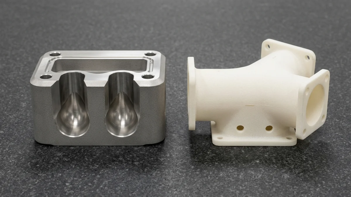
Cost levers. Crown internal metal passages into self-supporting 45° teardrop channels and place dual Ø4–5 mm drain holes near hollow SLS duct flanges—as shown on the sectioned DMLS 316L manifold and PA12 duct below—while nesting small parts and reserving fine tolerances for functional faces.
3D Printing Troubleshooting: Common Defects & Fixes
Most print defects trace back to geometry, orientation or post-processing, and each has a direct corrective action:
| Symptom | Likely Root Cause | Corrective Action |
|---|---|---|
| Warping or curled corners (SLS, MJF, FDM) | Uneven cooling across a large flat section | Add ribs or reduce flat area; rotate the part; raise wall thickness |
| Parts do not fit, holes too small | Normal shrinkage and ±0.20 mm per 100 mm accuracy | Compensate hole size in CAD or machine critical holes after printing |
| Brittle snap-fit breaks (SLA) | Low-elongation resin or a sharp snap-fit root | Switch to a tougher resin such as Taurus, add a root fillet of 0.5 mm or more, or move to SLS nylon |
| Weak layer bond (FDM, Z-axis) | Load applied across layers; Z-axis strength is often 20–50% lower than XY | Re-orient so load runs along layers, or use SLS or MJF nylon |
| Trapped powder or resin inside part | No or undersized drain holes | Add two or more Ø3–5 mm holes on non-critical faces |
| Cracks or distortion (metal) | Residual stress released after build | Vacuum stress-relieve on the build plate before Wire EDM cut-off; add overhang supports |
| Rough sealing surface | As-printed roughness Ra 6–12 µm | Leave machining stock and skim seal faces to Ra 0.8 µm (32 µin) |
When Not to Choose 3D Printing
Some parts are better made another way (see our CNC machining vs. 3D printing comparison for break-even thresholds). We will tell you before you pay for a print:
Precision Fits Under ±0.10 mm
Printed accuracy cannot hold bearing fits or sealing faces on its own. Choose CNC machining, or print and then finish-machine those critical features to ±0.010–0.020 mm.
See CNC Machining →Hundreds to Thousands of Parts
Beyond about 50–100 plastic parts, vacuum casting usually lowers unit cost; beyond a few hundred, injection molding gives the lowest unit cost and best surface finish.
See Injection Molding →Blocks, Plates and Brackets
A simple 6061-T6 bracket or plate is faster and more accurate when milled on 3-axis and 4-axis VMCs from solid bar. Reserve metal printing for complex, hollow or lattice shapes.
See CNC Milling →3D Printing Post-Processing: Stress Relief, Inserts & Surface Finishing
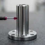
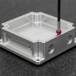
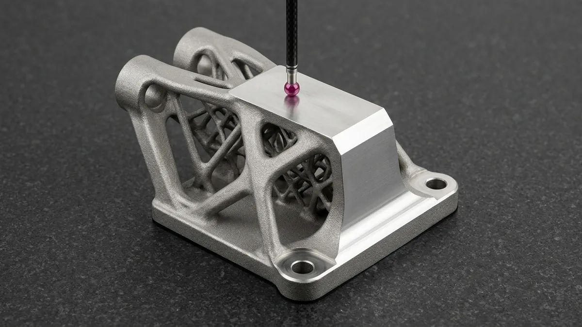
Printed parts leave the machine with support marks, residual stress or raw texture. Our in-house post-processing turns them into ready-to-assemble hardware—including CNC-milled DMLS titanium datums verified by tactile Zeiss Coordinate Measuring Machine (CMM) probing as shown below:
Vacuum Stress Relief, Wire EDM & CNC
DMLS metal builds undergo in-house vacuum stress-relief annealing on the build plate (such as Ti-6Al-4V at 800 °C for 4 h or AlSi10Mg at 270–300 °C) prior to Sodick Wire Electrical Discharge Machining (EDM) plate cut-off, support removal, H900/aging cycles, and CNC datum finish-machining (±0.010–0.020 mm).
Brass Inserts & Fasteners
Tapped plastic threads strip under repeated assembly. We install ultrasonic or heat-set brass inserts (M2–M8) so nylon and resin housings survive repeated disassembly.
Blasting, Smoothing & Metal Finishing
SLS and MJF nylons get bead blasting, dyeing or closed-loop vapor smoothing; clear SLA parts get #800–#2000 wet sanding plus UV clear lacquer. Metal parts get blasting, ASTM A967 passivation or MIL-A-8625 anodizing (grey tone on AlSi10Mg) in our surface finishing shop.
3D Printing Lead Times & Export Packaging
All times are Ex-Factory Production & Inspection Turnaround in business days. International air transit (DHL/FedEx/UPS) adds 3–5 business days and is separate. Finished parts ship nested in custom contour-cut foam trays alongside heat-sealed silver moisture-barrier vacuum pouches as shown below:
| Process & Scope | Typical Quantity | Ex-Factory Lead Time | Air Freight Transit |
|---|---|---|---|
| SLA, SLS, MJF, FDM or DLP, as printed | 1–50 pcs | 4–8 business days | Express air, 3–5 days transit |
| Plastic parts with surface finishing | 1–50 pcs | 7–12 business days | Express air, 3–5 days transit |
| Metal DMLS, vacuum stress-relieved & blasted | 1–5 pcs | 5–8 business days | Express air, 3–5 days transit |
| Metal DMLS with aging & CNC datum finishing | 1–10 pcs | 7–12 business days | Express air, 3–5 days transit |
| Low to medium batches | 10–1,000+ pcs | 7–30 business days | Air or sea by weight |
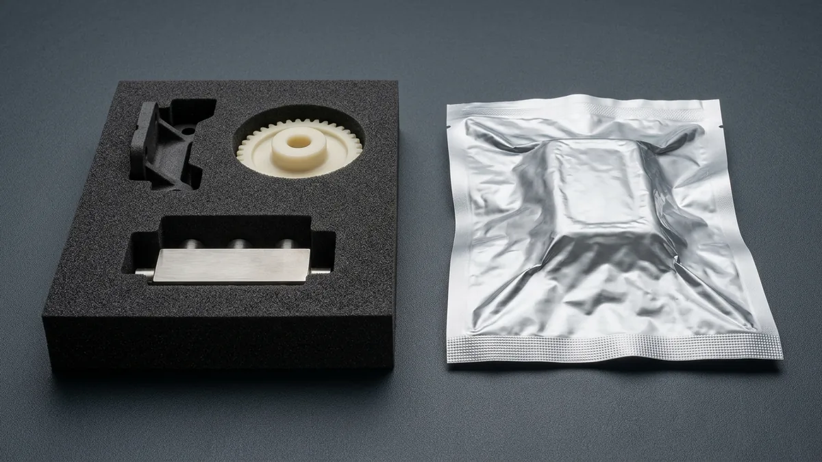
1. Contour-Cut EPE / EVA Foam
Fragile resin, nylon gears and post-machined metal manifolds sit in foam cavities cut to each part’s contour.
2. Silver Vacuum-Barrier Pouches
Heat-sealed metallized anti-static vacuum pouches with desiccant limit moisture uptake in nylon and resin parts.
3. Double-Wall Export Cartons
Reinforced corrugated cartons with edge protectors withstand drops and stacking in transit.
From 1 Prototype to 10,000+ Parts: Process Transition Guide
Process choice changes as quantity grows (see our 3D printing mass production engineering guide for batch scaling workflows). Costs are quoted per CAD after DFM review, so the table shows relative levels only:
| Stage | Quantity | Recommended Process | Tooling Investment | Unit Cost Profile | Recommended Application / When to Choose |
|---|---|---|---|---|---|
| Proof of Concept | 1–10 pcs | SLA, SLS, FDM or 4K DLP | Near Zero (Direct CAD Build) | Moderate to High | Fast design iteration without mold tooling |
| Functional Testing | 5–50 pcs | SLS, MJF or DMLS | Near Zero (Direct CAD Build) | Moderate | Real engineering materials, no mold |
| Pilot Batch | 20–100 pcs | Vacuum Casting | Low (silicone mold) | Low to Moderate | Molded-in color, low tooling risk |
| Bridge Production | 200–2,000 pcs | Aluminum Injection Molds | Moderate | Low | Production resins (12–18 business days T1; 18–35 business days batch) |
| Mass Production | 2,000–100,000+ pcs | Steel Injection Molds (P20/S136/H13) | Higher (hardened steel) | Volume-Driven Lowest | Lowest unit cost at volume |
How It Works: 4-Step Quote, Build & Delivery Process
Every project follows the same engineer-led path, from CAD review to delivery:
Send Your 3D CAD & Specs
Submit STEP, IGES or STL files with material, quantity and tolerance needs through our quote form. Files up to 100 MB are accepted, and everything is covered by Non-Disclosure Agreement (NDA) on request.
DFM Review & Quote
An application engineer checks walls, supports and orientation, then replies with a quote and DFM feedback within 24 hours. No file is processed without engineer contact.
Build, Finish & Inspect
Parts are built on calibrated industrial systems, post-cured or de-powdered, finished and inspected. 2.5D Optical Video Measuring System (VMS), Go/No-Go pin gauge, and mating fit-up inspection reports—plus tactile Zeiss CMM verification on CNC post-machined DMLS metal datums—are available on demand.
Protective Packaging & Air Transit
Parts are sealed in silver moisture-barrier vacuum pouches, cushioned in contour-cut foam cartons and sent by express air courier with tracking.
Industries We Serve with 3D Printed Parts
Typical applications from our recent build programs:
Consumer Electronics & Smart Devices →
Thin enclosures, snap-fit housings, 4K DLP connectors and clear light pipes for early fit and appearance checks.
Commercial & Automotive Lighting →
Clear SLA lenses wet-sanded and UV-coated for transparency, reflector prototypes and heat-resistant bezels.
Robotics, Jigs & Automation →
Lightweight end-of-arm tooling, clevis brackets, living-hinge clamps and PA12-CF motor plates.
Conformal Cooling Mold Inserts →
18Ni300 maraging steel (50–54 HRC) inserts with internal cooling channels that follow the part contour.
Aerospace & UAV Hardware →
Topology-optimized titanium brackets, centrifugal impellers and ULTEM air ducts with material traceability.
Medical Device Housings →
Surgical guide prototypes, diagnostic housings and optical-clear fluidic manifolds for lab automation.
Frequently Asked Questions About Industrial 3D Printing
Short answers on strength, accuracy, process choice, files and cost:
What is the strongest 3D printing material?
Precipitation-hardened 18Ni300 maraging steel (50–54 HRC) is the strongest 3D printing material in our range at roughly 2,050–2,100 MPa (297–305 ksi) tensile strength, followed by Inconel 718 (1,375–1,505 MPa), 17-4PH H900 (1,320–1,410 MPa) and Ti-6Al-4V (1,050–1,100 MPa). Among plastics, thermally cured PerFORM resin reaches 80 MPa (11.6 ksi) but is brittle, so PA12-GF glass-filled SLS nylon (51 MPa) or PA12-CF FDM nylon is the tougher choice. Orientation matters, because Z-axis strength is often lower than XY.
How accurate is 3D printing, and what tolerances can I expect?
Industrial 3D printing typically holds ±0.10–0.20 mm per 100 mm (±0.001–0.002 in/in) as printed: SLA and SLS hold ±0.20 mm per 100 mm, HP MJF holds ±0.15–0.20 mm, DMLS metal holds ±0.10 mm, and micro-detail 4K DLP holds ±0.02–0.03 mm on small parts. Larger parts carry proportionally larger deviation, and critical metal datums or bores can be CNC finish-machined in-house to ±0.010–0.020 mm.
SLS, MJF or SLA: which is best for functional or heat-resistant parts?
SLS or HP MJF nylon is the better choice for functional parts, because polyamide powder prints tough, support-free geometry. For heat resistance, PA12-GF glass-filled SLS nylon reaches 96 °C (205 °F) at 1.8 MPa and HP MJF PA 12 reaches 95 °C (203 °F). SLA suits smooth cosmetic parts, and PerFORM resin reaches 119 °C (246 °F) at 1.8 MPa after thermal cure.
What file formats do you accept for 3D printing quotes?
We accept STEP and IGES, which are preferred, and STL files. STEP keeps exact geometry, so our engineers can check walls and tolerances accurately. STL is a faceted approximation and suits visual parts. Include the material, quantity and any tolerance notes with the file. Our engineers review every submission and reply within 24 hours.
How can I reduce 3D printing cost?
Reduce cost by lowering machine time and post-processing. Orient parts to use fewer supports, hollow thick solid sections with drain holes, nest small parts together in powder-bed builds, and remove tight tolerances from non-functional faces. Our engineers suggest these changes during the free DFM review before you commit to a build.
Can metal 3D printed parts match wrought metal strength?
Yes, for static yield and tensile loads. Vacuum-annealed DMLS Ti-6Al-4V reaches ~960–1,000 MPa yield strength, above the 828 MPa ASTM B348 wrought minimum, and stress-relieved 316L yield (480–540 MPa) is about three times annealed plate (170 MPa). Because raw Ra 6–12 µm surfaces lower fatigue life, CNC finish-machined surfaces and vacuum stress-relief annealing are recommended for cyclic loads.
Need 3D Printed Prototypes or End-Use Metal Parts?
Upload your 3D CAD models (STEP/IGES/STL) and 2D tolerance drawings for a comprehensive DfAM review, build-orientation strategy, and custom production quotation.