PRECISION TOOLING · SCIENTIFIC INJECTION MOLDING · RAPID BRIDGE TO MASS PRODUCTION
Custom Plastic Injection Molding & Rapid Tooling Services
Rapid Tooling & MoldingRapid Aluminum Bridge ToolingP20 / NAK80 / S136 Tool SteelsTight ISO 20457 Tolerances18–25 Day T1 Trial SamplesIn-House Moldflow & CMM Verification
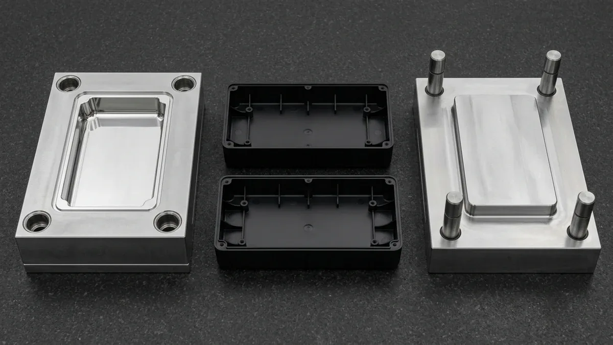
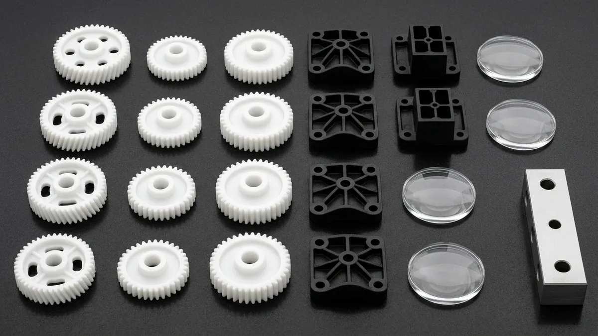
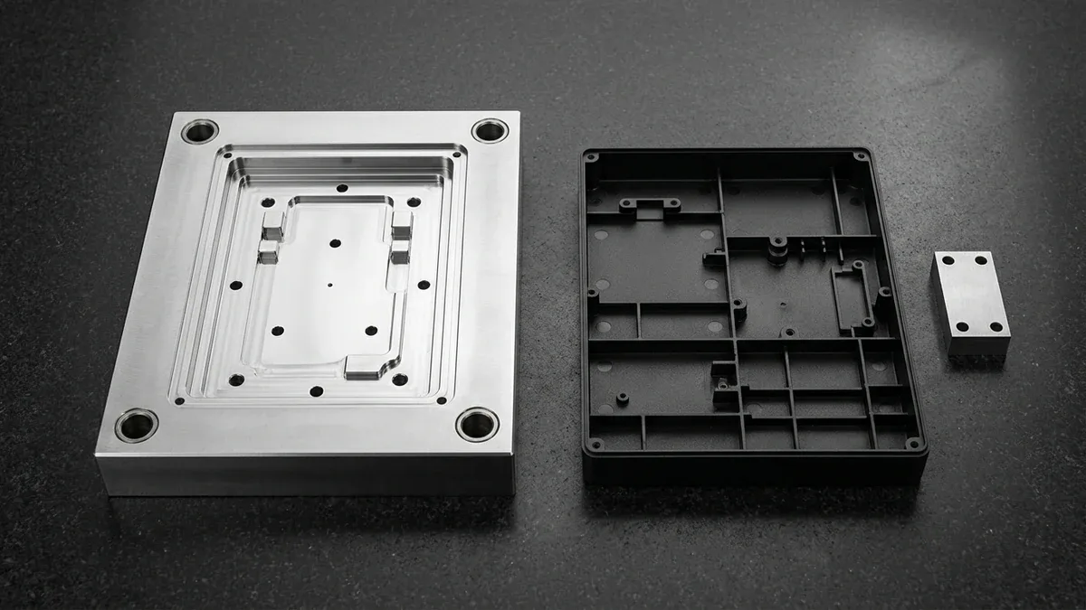
At AS Prototypes, we bridge the critical gap between early-stage prototyping and full-scale series manufacturing. Combining high-speed CNC mold milling, precision mirror sinker EDM, and scientific injection molding presses (50T to 850T), we deliver production-quality thermoplastic parts with exceptional dimensional accuracy. Whether you require 500 prototype units via rapid aluminum bridge tooling or 500,000+ precision components through hardened multi-cavity steel molds, our in-house engineering team provides complete turnkey solutions from automated DFM feedback to final Zeiss CMM (available upon request) inspection.
18 – 25 Days
T1 Sample Delivery
Rapid bridge tooling & first shot verification
±0.05 mm
Typical Molded-Part Tolerance
ISO 20457 / DIN 16742 tolerance grades (tighter on select features after T1 tuning)
1,000,000+
Class 101 Shot Life
Hardened H13 & S136 ESR stainless steels
50T – 850T
Clamping Fleet
All-electric & servo-hydraulic presses
1. Rapid Tooling & Bridge Injection Molding: Fast-Track Your Production
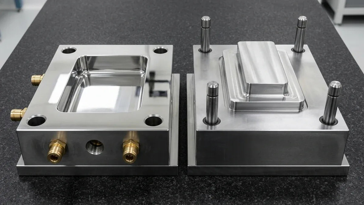
Traditional production tooling often demands 6 to 12 weeks of fabrication time and heavy upfront capital commitment. For agile hardware startups, medical device innovators, and automotive tier suppliers, extended lead times present a substantial barrier to rapid market entry. Rapid injection molding (bridge tooling or prototype tooling) solves this challenge by leveraging modular master mold bases (MUD), pre-hardened tool steels (P20 / NAK80) or aerospace 7075-T6 aluminum, and high-speed CNC machining to deliver functional T1 trial parts in 18 to 25 business days.
Key Advantages of AS Prototypes Rapid Tooling
1
Accelerated Time-to-Market: Receive production-grade T1 parts in 18 to 25 business days, then scale from 100 to 100,000+ parts, enabling physical functional testing, regulatory pilot validation, and initial market deployment ahead of full-scale production.
2
Up to 70% Lower Upfront Investment: By utilizing standardized master mold bases and high-efficiency core/cavity inserts, we drastically lower tooling capital while delivering production-grade geometry.
3
Agile Tool Modification & Iteration: Interchangeable mold inserts allow for quick engineering change orders (ECOs), draft adjustments, and wall modifications without re-machining an entire mold base.
4
End-Use Production Resins: Unlike 3D printing or urethane
vacuum casting, parts are molded using native engineering polymers (glass-filled PA66, PC, POM, PEEK, ABS) matching exact mechanical, thermal, and chemical requirements.
2. Engineering Design for Manufacturability (DFM) Guidelines
Achieving seamless injection molding begins at the digital CAD stage. Designing plastic components without accounting for polymer melt behavior, thermal shrinkage, and mold ejection physics leads to sink marks, voids, warpage, and premature tool wear. Our engineering team conducts an exhaustive DFM analysis prior to tool steel cutting, focusing on four primary geometric pillars:
RULE 01
Nominal Wall & Uniformity
Prevent Sinks & Voids
Maintain uniform wall thickness across the component. When wall transitions are unavoidable, integrate gradual chamfers or ramps (minimum 3:1 length-to-depth ratio) to ensure consistent cooling and eliminate internal vacuum voids.
RULE 02
Draft Angles & Texture
Clean Part Ejection
Incorporate a minimum draft angle of 1° to 2° per side on polished surfaces. For Mold-Tech or spark textures, add 1.0° to 1.5° draft per 0.025 mm (0.001″) texture depth to prevent drag marks and scuffing.
RULE 03
Structural Ribs & Bosses
Rigidity Without Mass
Design rib thickness to measure 50% to 60% of the adjacent nominal wall with 0.5°–1.0° draft and 0.25t–0.4t base radii. Screw bosses require 60% nominal wall thickness supported by triangular gussets.
RULE 04
Parting Lines & Gating
Invisible Witness Marks
Align parting lines along sharp geometric corners. We deploy submarine sub-gates for automated de-gating, edge gates for heavy structural sections, or hot-runner valve gates for zero-scrap cosmetic surfaces.
SPI Tooling Classifications & Capability Matrix
We engineer molds according to standardized Society of the Plastics Industry (SPI) classifications, matching tool steels, heat treatment hardness, and cavity metallurgy to your exact volume requirements:
SPI Injection Mold Tooling Classes (105, 103, 101), Core Steels & T1 Sample Lead Times| SPI Tooling Class | Core & Cavity Steel | Shot Life Capacity | Achievable Tolerances | Surface Finish Standards | T1 Lead Time |
|---|
| Class 105 (Rapid Prototype) | Aluminum 7075-T6 (bridge tooling) | 500 – 10,000 shots | ±0.05 mm (±0.002″) | SPI B-1 (600 Grit), Mold-Tech MT-11010 | 18 – 25 business days |
| Class 104 (Low-to-Mid Volume) | P20 (28–32 HRC) / NAK80 (38–42 HRC) | 10,000 – 100,000 shots | ±0.05 mm (±0.002″) | SPI A-3, Mold-Tech fine EDM texture | 22 – 30 business days |
| Class 103 (Production Tooling) | Hardened H13 (48–52 HRC) / S136 Stainless | 100,000 – 500,000 shots | ±0.05 mm (±0.002″) | SPI A-2 (High Gloss Diamond), Optical Polish | 24 – 32 business days |
| Class 101/102 (High-Volume Multi) | Premium H13 / S136 ESR (50–54 HRC) | 1,000,000+ shots (Guaranteed) | ±0.020 mm (tooling inserts); ±0.05 mm (molded part) | SPI A-1 (Mirror Finish), Laser Engraving | 28 – 35 business days |
| Specialty Tooling & Mold Types | Interchangeable core inserts, hydraulic side-action sliders, mechanical lifters, unscrewing molds for internal threads, multi-cavity family molds, 2K multi-shot rotary molds, and heated hot-runner systems machined via precision CNC mold machining and wire/sinker EDM tooling. |
3. Advanced Molding Capabilities: Overmolding & Insert Molding
Beyond standard single-cavity molding, AS Prototypes provides high-precision multi-material and hybrid manufacturing solutions designed to streamline assembly and elevate product durability:
Multi-Shot (2K)
Two-Shot (2K) Multi-Material Overmolding
Bonds soft elastomeric grips (compatible TPU and TPE grades; silicone via bonding-grade LSR or mechanical interlock) onto rigid plastic substrates (PC, ABS, Nylon) without adhesive glues, enhancing ergonomics, sealing (IP67/IP68), and impact protection.
Hardware Encapsulation
Precision Threaded Metal Insert Molding
Accurately encapsulates knurled brass threaded inserts, electrical stamped contacts, or hardened steel pins during the injection cycle, providing durable, reusable threads that resist pull-out and torque forces.
High Performance
High-Performance Engineering Resins
Our injection molding facility processes a comprehensive selection of engineering thermoplastics, custom color-matched masterbatches, and high-performance polymers optimized for shrinkage and thermal stability:
Comprehensive Engineering Thermoplastics & Material Selection Guide
Selecting the optimal plastic resin requires balancing mechanical load requirements, continuous operating temperature, electrical resistance, flammability ratings, and raw resin shrink rates. At AS Prototypes, we process a vast inventory of commercial polymers, glass-reinforced formulations, and high-performance specialty thermoplastics:
Injection Molding Thermoplastic Resins, Recommended Wall Thicknesses & Shrinkage Rates| Polymer Material | Recommended Wall | Shrink Rate | Key Performance Attributes | Typical Industry Applications |
|---|
| ABS (Acrylonitrile Butadiene Styrene) | 1.15 – 3.0 mm | 0.4 – 0.7% | High impact resistance, excellent aesthetic surface finish, cost-effective, electroplatable. | Consumer electronics enclosures, automotive trim, drone canopies. |
| PC (Polycarbonate) | 1.20 – 3.8 mm | 0.5 – 0.7% | Optical transparency (>88%), outstanding heat deflection, extreme impact strength. | Optical lenses, light pipes, ruggedized handheld housings, display covers. |
| PC/ABS Blend | 1.20 – 3.5 mm | 0.5 – 0.7% | Combines PC heat/impact resistance with ABS processability; UL94 V-0 available in FR grades. | Automotive dashboards, telecommunications hardware, medical equipment enclosures. |
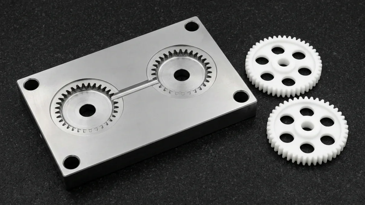
| POM (Polyoxymethylene / Delrin) | 0.80 – 3.2 mm | 1.8 – 2.5% | Low coefficient of friction, high dimensional stability, self-lubricating, wear-resistant. | Gears, pulleys, bearings, sliding mechanisms, snap-fit assemblies. |
| PA66 + 30% GF (Nylon Glass-Filled) | 1.00 – 3.0 mm | 0.3 – 0.8% | Exceptional tensile stiffness, heat deflection temperature around 250°C, replaces cast metal. | Under-the-hood automotive components, structural brackets, power tool housings. |
| PEEK (Polyetheretherketone) | 1.50 – 4.0 mm | 1.2 – 1.5% | Continuous use at 250°C, chemical inertness, biocompatible, ultra-high tensile strength. | Medical device surgical instruments, aerospace bushings, semiconductor fixtures. |
| TPU / TPE (Thermoplastic Elastomers) | 1.00 – 3.5 mm | 0.5 – 2.5% | Rubber-like elasticity (Shore 40A to 95A), vibration damping, overmolding compatibility. | Overmolded ergonomic grips, sealing gaskets, flexible protective boots. |
4. Surface Finish Standards: SPI Polishing & Mold-Tech Textures
The surface appearance and tactile feel of a molded part directly reflect the craftsmanship of the mold cavity. AS Prototypes offers standard SPI (Society of the Plastics Industry) surface finishes and Mold-Tech photo-chemical grain textures via our in-house surface finishing division:
SPI A-1 to A-3
Diamond Buff Mirror
Ra 0.012 – 0.10 μm
Hand-polished with fine diamond paste down to Ra 0.012 μm. Delivers optical clarity on PMMA/PC lenses and high-gloss consumer electronics.
SPI B-1 to B-3
Grit Paper Semi-Gloss
Ra 0.05 – 0.32 μm
Finished with 320 to 600 grit paper (Ra 0.05–0.32 μm). Effectively conceals minor machining marks economically for semi-cosmetic parts.
SPI C-1 to C-3
Fine Stone Matte
Ra 0.35 – 0.80 μm
Prepared with 320–600 grit polishing stones (Ra 0.35–0.8 μm). Ideal for internal non-cosmetic structural housings and concealed brackets.
SPI D-1 to D-3
Dry Blast Texture
Ra 1.00 – 3.20 μm
Glass bead or aluminum oxide blasted diffuse texture, creating comfortable ergonomic grip and hiding fingerprint marks.
Mold-Tech & VDI
Photo-Etch & Spark
MT-11000 / VDI 12-36
Chemical etching reproducing MT-11000 leatherette/geometric grains, and sinker EDM spark erosion textures for premium tactile finish.
5. Quality Assurance: Moldflow Simulation & Zeiss CMM Metrology (Available Upon Request)
At AS Prototypes, dimensional precision is guaranteed through rigorous engineering controls at every phase of moldmaking and part production:
Rheology Analysis
01. Moldflow Simulation
Virtual Kinematics & Rheology
Prior to steel cutting, our master toolmakers conduct multi-variable mold filling simulations. We calculate fill pressure, clamp tonnage, shear rate, fiber orientation, air traps, and volumetric shrinkage, virtually eliminating short shots and excessive part warpage.
Zeiss Metrology (On Demand)
02. Zeiss CMM Dimensional Inspection
Micron-Level Verification
We perform coordinate measuring machine (CMM) inspection on critical mold electrode geometries, core/cavity inserts, and T1 trial molded parts to verify mold insert and T1 part critical dimensions to ±0.025 mm (±0.001″).
FAIR Documentation
03. First Article Inspection (FAIR)
Full QC Documentation
Complete dimensional inspection documentation (including GD&T verification, material melt flow index testing, and optical projector profiles) is provided with your T1 sample shipment for formal engineering sign-off.
6. Frequently Asked Questions (FAQ)
What is the typical turnaround time for rapid prototype tooling and T1 sample delivery?+
For rapid prototype bridge tooling (SPI Class 105 utilizing 7075-T6 aluminum), our typical ex-factory lead time for T1 test samples is
18 to 25 business days from design approval, while high-precision production molds (Class 103/101 hardened H13 or S136 stainless steel) require
24 to 35 business days ex-factory (international DHL/FedEx/UPS air transit adds 3 to 5 days). For deep engineering analysis of tooling architecture and thermal cycle optimization, explore our
prototype injection molding & rapid tooling guide and our
conformal cooling vs. conventional mold cooling DFM guide.
What dimensional tolerances can AS Prototypes achieve on custom injection molded parts?+
Standard plastic injection molding tolerances conform to ISO 20457 / DIN 16742 standards, typically maintaining ±0.05 mm (±0.002″) on critical features. For high-precision core/cavity inserts and dimensionally stable engineering polymers (such as unfilled PC, POM, or PEEK), our multi-axis CNC moldmaking allows us to achieve molded-part tolerances of ±0.05 mm (±0.002″) (±0.025 mm on mold inserts).
Does AS Prototypes provide a complimentary DFM analysis before cutting tool steel?+
Yes. Every 3D CAD model submitted for quotation undergoes a comprehensive, complimentary Design for Manufacturability (DFM) review by our senior tooling engineers. We evaluate wall thickness distribution, draft angles, parting lines, gate positioning, and potential sink or weld line hazards, providing actionable recommendations to optimize part quality and reduce mold fabrication costs before machining begins.
What mold steel do you recommend for rapid bridge tooling vs. mass production?+
For rapid bridge tooling and volumes up to 100,000 parts, we recommend pre-hardened P20 or NAK80 steel (or aerospace 7075-T6 aluminum for fast cooling cycles and lowest upfront cost). For high-volume series production exceeding 100,000 to 1,000,000+ shots, or when processing abrasive glass-filled resins, we utilize fully through-hardened H13 tool steel (48–52 HRC) or S136 ESR stainless steel (50–54 HRC) for superior corrosion and wear resistance.
Ready to Build Your Injection Mold & Run Production Parts?
From rapid prototype bridge tooling in 18 to 25 days to high-volume Class 101 production molds, AS Prototypes delivers precision plastic parts with zero quality compromise. Upload your 3D CAD models (STEP/IGES) to receive a detailed DFM report and an instant quote from our master moldmakers.
• Strict NDA Confidentiality• Complimentary DFM & Moldflow• Zeiss CMM Verification (On Request)• 18–25 Day T1 Verification