CNC Machining • Multi-Axis Milling • Tight-Tolerance Prototypes
Custom CNC Milling Services & Precision Multi-Axis Machining
Precision Milling
3, 4 & 5-Axis Simultaneous
±0.010 mm Precision Machining
4–8 Day Prototype Turnaround
30+ Production Materials
Zeiss CMM Metrology (Upon Request)
At AS Prototypes, our in-house CNC machining facility operates high-speed 3-axis, 4-axis, and simultaneous 5-axis CNC vertical and horizontal milling centers. Using high-precision multi-point rotary cutting tools, automated tool changers, and advanced CAD/CAM simulation, we manufacture custom mechanical prototypes and low-to-medium production runs with standard tolerances of ISO 2768-mK, precision milled features held to ±0.010 mm, and critical bored diameters down to ±0.005 mm (±0.0002″).
What Is CNC Milling and How Does It Work?
CNC milling (Computer Numerical Control milling) is a subtractive machining process where computer-guided rotary cutting tools systematically remove material from a raw billet. Digital G-code programs dictate exact tool trajectories, spindle speeds (up to 18,000 RPM), feed rates, and high-pressure flood coolant across aerospace aluminum, stainless steels, titanium, brass, and engineering plastics.
Vertical Machining Center (VMC)
Vertical Spindle
Top-down tool engagement optimized for plates, shallow cavities, dies & rapid prototype setups.
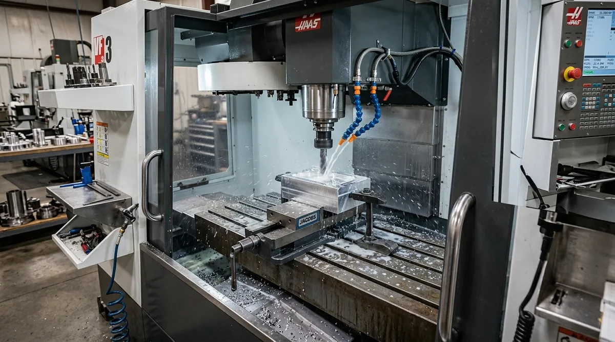
• Toolpath Access: Downward Z-axis spindle engagement provides ideal visibility and fast clamping for prismatic parts.
• Cost Efficiency: Fast setup turnaround using standard pneumatic and precision mechanical vises.
• Ideal Geometries: Enclosure faceplates, optical mounts, heat sink fins, and 2.5D/3D surface pockets.
Horizontal Machining Center (HMC)
Horizontal Spindle
Gravity-assisted chip fall & multi-face tombstone pallet indexing for continuous production runs.
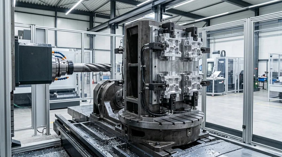
• Chip Evacuation: Heavy chips fall away freely by gravity, preventing recutting and extending cutter life.
• 4-Sided Tombstones: Multi-sided rotary tombstones machine multiple parts per pallet without stopping.
• Ideal Geometries: Deep transmission housings, manifold blocks, pump bodies, and high-volume castings.
Overview of the CNC Milling Process & Workflow
Our engineering workflow follows four synchronized milestones to ensure design fidelity and tight dimensional repeatability:
Step 01
3D CAD & DFM Review
Review 3D models (STEP/IGES) and 2D drawings to verify wall thickness, pocket radii, tap depths, and GD&T.
Step 02
CAM Toolpathing
Generate G-code using constant-engagement trochoidal clearing and adaptive finishing to eliminate tool chatter.
Step 03
Fixturing & Probing
Parts locked in 5-axis vises or vacuum chucks. Renishaw optical probes set datums and calibrate cutter offsets.
Step 04
Machining & CMM
High-pressure flood coolant roughing and finishing passes, followed by ultrasonic cleaning and Zeiss CMM dimensional verification (available upon request).
Climb Milling vs. Conventional: In CNC milling, our machines operate primarily in climb milling (down milling) mode, where the cutter enters at maximum chip thickness and tapers to zero. This minimizes cutting friction, preserves cutter edges, dampens vibration, and delivers fine surface finishes down to Ra 0.8 μm (Ra 0.4 μm achievable with micro-stepover high-speed finishing).
Thin-Wall Stability & Stress Relief: For aerospace brackets and deep enclosures with pocket wall thickness ≤ 1.0 mm, internal rolling stresses in raw billets can cause part distortion after roughing. AS Prototypes applies balanced roughing passes across opposing sides and intermediate stress-relief annealing before final precision skim milling to guarantee true planar flatness and perpendicularity.
Face Milling Mechanics
Face Action
High-rigidity indexable shell mills for rapid planar material removal & datum flatness.
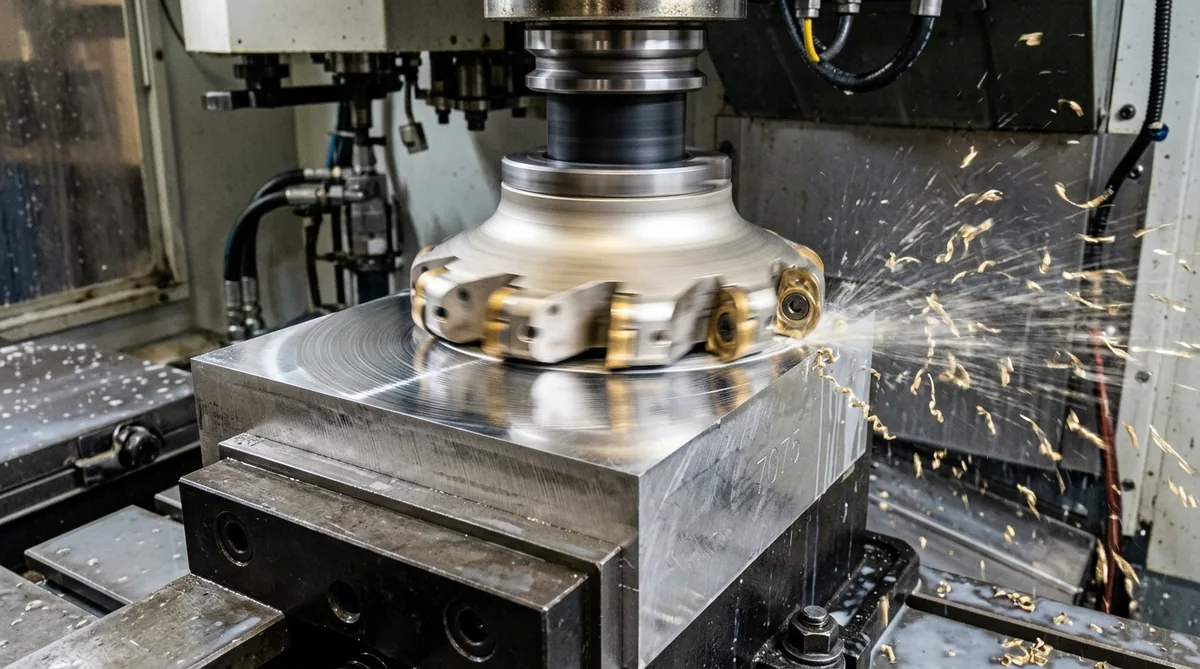
• Cutting Action: Performed primarily by face and corner inserts perpendicular to spindle axis.
• Surface Flatness: High axial spindle stiffness delivers planar flatness within ±0.01 mm.
• Best Uses: Large reference plates, structural flanges, fixture plates, and engine decks.
Peripheral & End Milling
Side Flutes
Helical side-cutting flutes for precision vertical walls, deep pockets, slots & profiles.
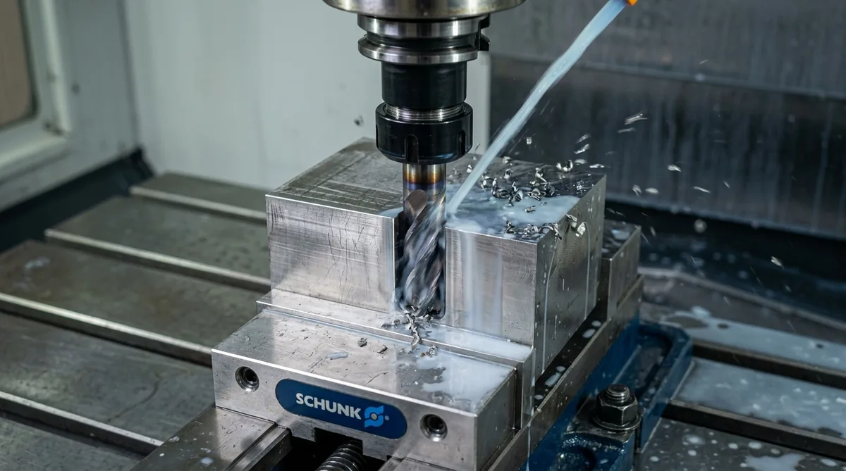
• Cutting Action: Performed along peripheral helical flutes parallel to cutter rotational axis.
• Rigidity Control: Short tool stick-out (L/D < 3:1) minimizes deflection, ensuring straight walls.
• Best Uses: Cavity walls, O-ring grooves, stepped shoulders, keyways, and external contours.
Core CNC Milling Operations: Face, Peripheral & End Milling
Our multi-axis milling centers execute standard and specialized cutting operations conforming to general tolerances ISO 2768-mK (ISO 2768-fH upon request), with precision milled features held to custom drawing tolerances down to ±0.010 mm:
Face Milling
Perpendicular Axis
Uses indexable face mills with bottom and side inserts to machine broad, ultra-flat reference datums and precision mounting faces.
Capability: Flatness ≤ 0.01 mm • Ra 0.8 μm
Plain / Slab Milling
Parallel Axis
Cutter axis lies parallel to the surface. Wide slab cutters with coarse helical teeth execute high material removal rates during heavy roughing.
Capability: High MRR bulk stock excising • Wide plate roughing
Angular Milling
Angled Spindle / Tool
Spindle is tilted relative to workpiece or uses angular cutters. Ideal for machining 45°, 50°, 55°, 60° dovetail slides, serrations, and chamfers.
Capability: Precision dovetail ways • Chamfers ±0.02 mm
Uses custom concave, convex, or corner-rounding cutters to form irregular 3D contours, ball grooves, and aerodynamic blends in a single pass.
Capability: Hemispherical pockets • Concave / convex blends
Specialized Operations & Tool Carousel Automation
Beyond basic roughing and facing, modern CNC milling relies on specialized cutters and rapid automated tool changers (ATC) to produce complex mechanical mating features with zero secondary re-fixturing:
• Slot & Straddle Milling: Gang-mounted side-and-face cutters machine parallel retaining slot pairs and keyways in a single stroke, maintaining absolute bilateral parallelism.
• Thread Milling: Multi-axis circular interpolation rotates helical thread mills to cut internal and external threads from M2 up to large pitches without tap breakage risk.
• Dual-Contact ATC Carousels: 24- to 40-station tool carousels with Big Plus (dual-contact taper and flange) holders achieve chip-to-chip tool changes in under 1.8 seconds.
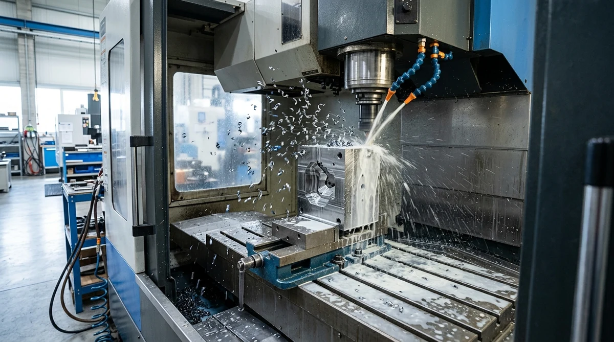
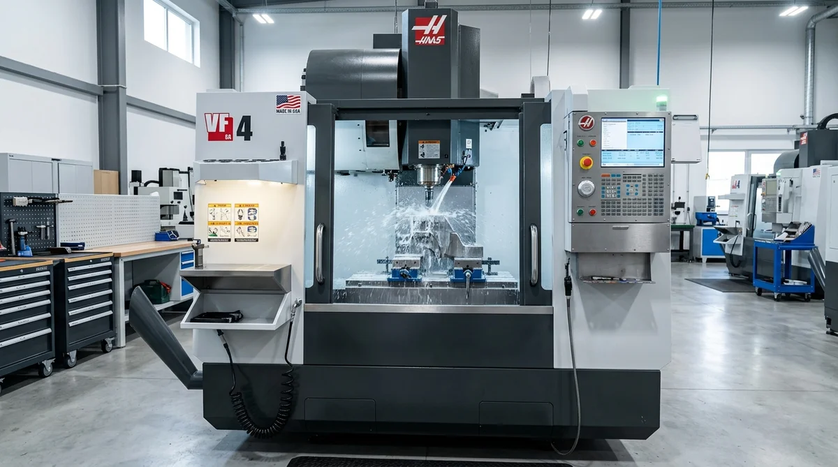
Figure 1: Heavy vertical machining center (VMC) face milling a hardened tool steel mold cavity plate with high-pressure flood coolant delivery.
Digital 5-Axis CAM Simulation & Collision Verification
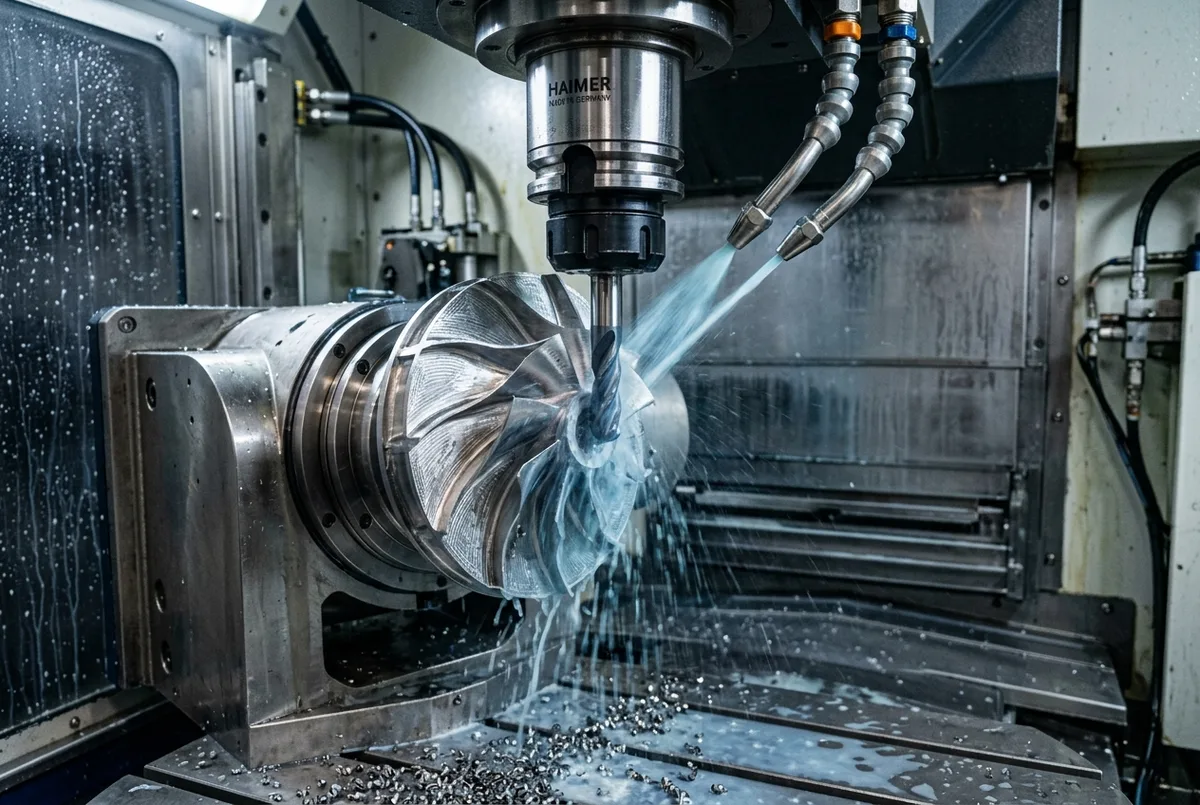
Figure 2: Continuous 5-axis CNC simultaneous milling of an aerospace titanium alloy impeller blisk with dedicated flood coolant.
Before metal cutting commences on our simultaneous 5-axis machines, CAM programmers simulate the entire kinematic sequence inside digital twin software:
• Kinematic Collision Avoidance: Checks real-time clearances between the spindle nose, tool shank, trunnion table, clamps, and the raw billet to prevent crashes.
• Constant Scallop Height: 5-axis swarf cutting and point milling maintain uniform cusp height across organic aerodynamic blends and impellers.
• Feed Rate Optimization: Automatic feed adjustments compensate for chip thinning during high-speed trochoidal corner engagements, extending tool life.
Key Considerations for CNC Milling Component Design & Axis Selection
Selecting the optimal milling machine configuration depends directly on workpiece geometry complexity, setup counts, and required GD&T precision:
| Milling Machine Type | Kinematic Axes | Workpiece Complexity | Primary Applications | Achievable Tolerances |
|---|
| Vertical Machining Center (VMC) | 3-Axis (X, Y, Z) | Prismatic, 2.5D pockets, planar surfaces | Enclosure plates, sensor housings, heatsinks | ±0.010 mm (±0.0004″) |
| 4-Axis VMC / HMC | 4-Axis (X, Y, Z + A or B) | Cylindrical features, angled radial holes, cams | Camshafts, turbine nozzles, multi-sided brackets | ±0.008 mm (±0.0003″) |
| Simultaneous 5-Axis Center | 5-Axis (X, Y, Z + A/B/C) | Undercuts, deep complex pockets, organic impellers | Aerospace blisks, surgical bone plates, robotic arms | ±0.015 mm (Contoured) / ±0.005 mm (Bored Features) |
| Traveling Column / Ram-Type | Long-Bed 3- to 5-Axis | Long extrusions, heavy frames > 3,000 mm | Chassis beams, wing spars, large machine bases | ±0.020 mm (±0.0008″) |
| Gantry / Bridge-Type Center | Heavy 3- to 5-Axis Gantry | Heavy tooling, die casting molds, structural tooling | Automotive press dies, aerospace composite molds | ±0.015 mm (±0.0006″) |
Industrial Types of CNC Milling Machines
Knee-Type & Vertical Machining Centers (VMC)
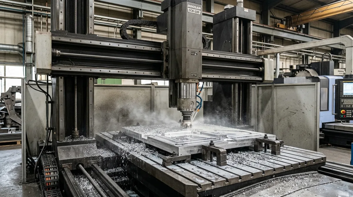
While traditional knee-type mills rely on a vertically translating knee casting, modern industrial CNC vertical machining centers (VMCs) utilize a rigid bed-type C-frame architecture. The heavy Meehanite cast iron base supports the X/Y saddle and table directly on ground linear guideways, while the high-speed spindle headstock (up to 18,000 RPM) travels along the vertical Z-axis column.
Best for: Rapid prototype setups, mold core details, optical brackets, and multi-cavity enclosures.
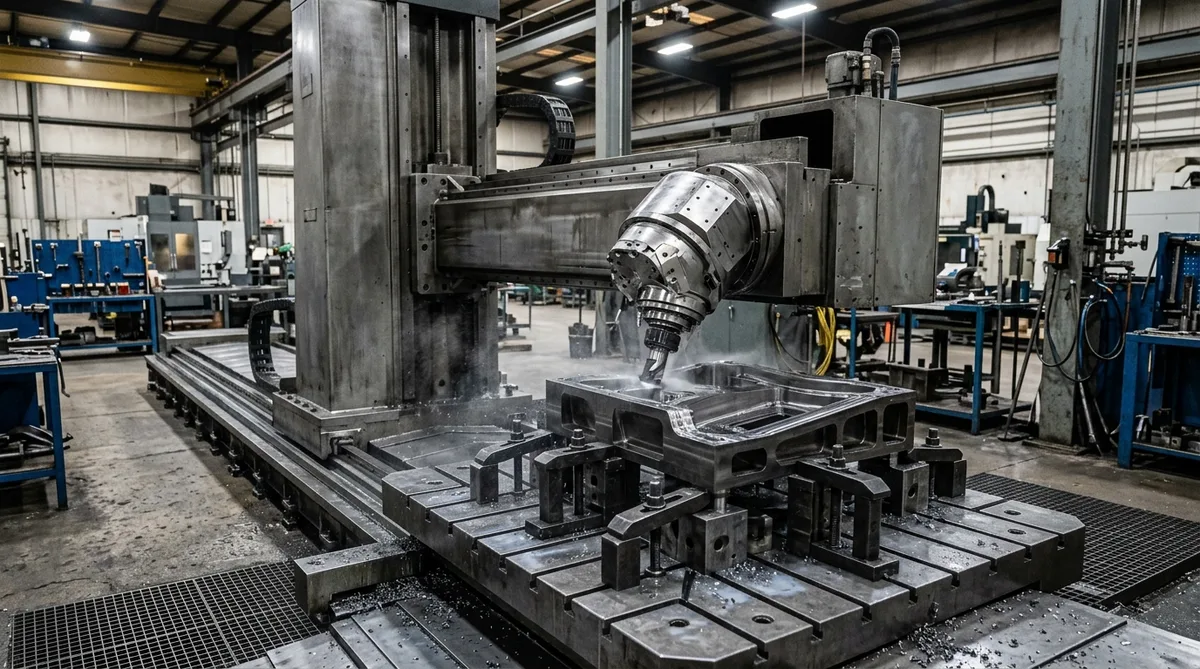
Traveling Column / Ram-Type CNC Milling Structure
Independent Stationary Workbed with Moving Longitudinal Column and Extending Horizontal Ram
• X-Axis (Longitudinal Column Stroke)• Y-Axis (Horizontal Ram Cross Stroke)• Z-Axis (Vertical Spindle Feed)
1. Extending Ram (Y)800 – 1,200 mm
Hardened box guideways with hydrostatic bearings ensure zero droop at maximum stroke.
2. Column (X-Axis)Up to 6,000 mm
Cast iron column moves longitudinally along bed, keeping cutting dynamics uniform.
3. Stationary Bed> 5,000 kg
Heavy parts rest on rigid stationary foundation, eliminating table inertia deflection.
4. Spindle Head (Z)600 – 1,000 mm
Vertical ram saddle with dual counterbalancing cylinders drives geared or motorized spindles.
5. Roller GuidesPreload Class P
Preloaded linear roller guide packs provide high vibration damping across rapid traverses.
6. Pendulum MachiningDual Workzones
Bed split into two independent clamping zones enables continuous loading without spindle stop.
Heavy Bed-Type, Planer & Gantry CNC Milling Systems
For massive mold bases, die tooling, and structural beams exceeding 2,000 × 1,500 mm, bridge and gantry milling centers utilize dual-synchronized linear drives along twin support columns. The rigid bridge structure spans the entire bed width, eliminating cantilever deflection during heavy roughing with 50-taper spindles.
Best for: Injection mold cavities, automotive stamping dies, aerospace tooling jigs, and marine engine blocks.
Frequently Asked Questions (FAQ) About CNC Milling
What machining tolerances can AS Prototypes achieve with CNC milling?
Our standard CNC milling conforms to ISO 2768-mK. For critical features, precision bearing journals, and dowel pin holes, our 3-axis, 4-axis, and simultaneous 5-axis milling centers achieve precision down to ±0.005 mm (±0.0002″). Critical dimensions can be verified upon request in our climate-controlled metrology lab using Zeiss CMM touch probes.
When should I choose 5-axis simultaneous milling over standard 3-axis milling?
5-axis simultaneous milling is ideal when your part has complex organic 3D surfaces (such as impellers and blisks), deep pockets requiring short rigid cutters to eliminate chatter, or multi-sided features that would otherwise require 3 to 5 separate fixture setups. Choosing 5-axis reduces cumulative clamping error and delivers superior surface finishes down to Ra 0.4 μm.
What engineering materials do you stock and machine for CNC milled components?
We stock over 30 traceable engineering metals and plastics, including aluminum (6061-T6, 7075-T6, 2024, 5052), stainless steels (304, 316L, 17-4 PH), titanium (Grade 2, Ti-6Al-4V Grade 5), tool steels (D2, A2, P20), brass, copper, and polymers such as POM (Delrin), PEEK, PTFE, Nylon, and ABS.
What is the turnaround time for custom CNC milled prototypes and production batches?
Rapid mechanical prototypes can be machined, deburred, and inspected within 4 to 8 business days (7 to 12 business days if secondary anodizing, electroplating, or powder coating is required). Low-to-medium production batches (50 to 5,000+ pieces) typically complete ex-factory inspection in 7 to 30 business days depending on geometric complexity and post-processing.
Need High-Precision Custom CNC Milled Parts?
At AS Prototypes, we operate high-speed 3-axis, 4-axis, and 5-axis CNC milling centers capable of tight tolerances down to ±0.005 mm. Upload your 3D CAD models (STEP/IGES) for a free DFM manufacturability review and guaranteed quotation within 24 hours.
🔒 Strict NDA Confidentiality • ISO 2768 Standard Tolerances • Zeiss CMM Inspection (Available Upon Request)