Precision Wire EDM Services: Wire & Sinker Electrical Discharge Machining
AS Prototypes delivers precision wire EDM services and specialized Electrical Discharge Machining (EDM) solutions at our in-house facility for hardened tooling and intricate micro-geometries. Operating Sodick 4-axis linear-motor slow-wire EDM and Makino Computer Numerical Control (CNC) sinker EDM, we hold ±0.005 mm (±0.0002″) tolerances and Ra 0.2 μm (8 μin) finishes with zero cutting force.
Core EDM Machining Capabilities & Technologies
1. Multi-Axis Slow Wire EDM (Sodick 4-Axis X/Y/U/V Linear-Motor Cutting)
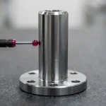
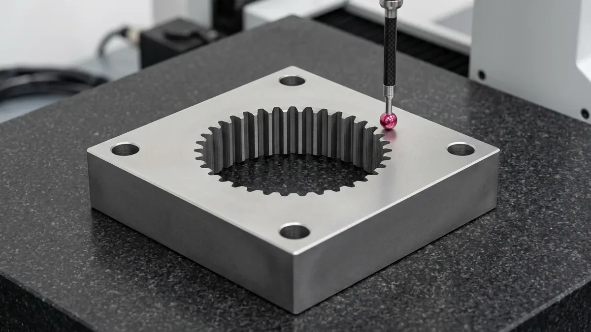
Wire Electrical Discharge Machining (Wire EDM) feeds a taut Ø0.10–0.25 mm brass or tungsten wire through chilled deionized water across our Sodick ALN400Qs linear-motor fleet (400 × 300 × 250 mm travel) to hold ±0.005 mm (±0.0002″) tolerances, as verified on the hardened D2 internal spline die block under Coordinate Measuring Machine (CMM) inspection.
- Independent 4-Axis X/Y/U/V Tapers: Simultaneous upper and lower diamond-guide interpolation cuts precision die clearance reliefs, extrusion transitions, and ruled tapers up to ±25°.
- Sub-Millimeter Corner Radii: Delivers crisp internal corners down to R0.07 mm (0.003″) on through-thickness die profiles, impossible with conventional rotary end mills.
- Zero Cutting Force: Non-contact thermoelectric spark erosion eliminates mechanical tool deflection, machining hardened punches, dies, and fragile 0.20 mm (0.008″) thin walls burr-free.
2. CNC Sinker / Die-Sinking EDM (Makino Blind-Cavity & Deep-Rib Erosion)
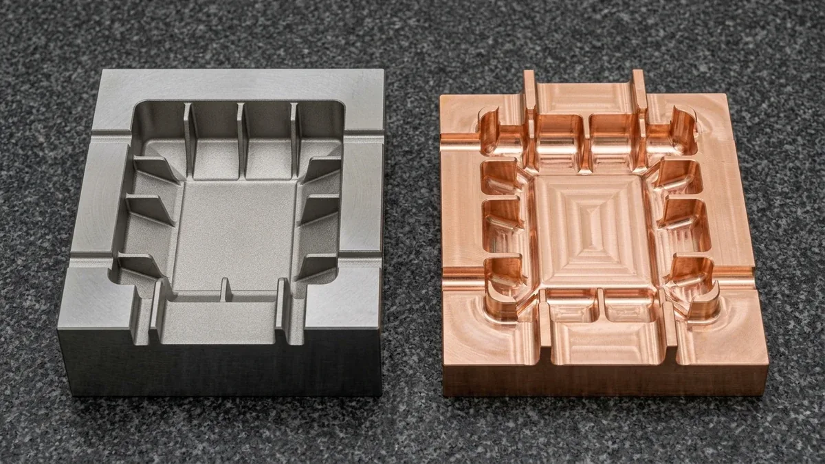
CNC sinker EDM plunges custom 3D electrodes submerged in hydrocarbon dielectric oil on our Makino EDNC85 system (800 × 500 × 350 mm travel) to erode blind cavities within ±0.010 mm (±0.0004″), as paired on the granite plate showing a hardened tool steel deep-rib mold insert beside its CNC-milled electrolytic copper electrode.
- Custom Electrode Engineering: In-house high-speed CNC milling of ultra-fine isostatic graphite, Electrolytic Tough Pitch (ETP) copper, and wear-resistant copper-tungsten (CuW) electrodes for sharp carbide or deep-rib cavities.
- Multi-Axis CNC Orbiting: Programmable planetary, spherical, and vector spark-erosion cycles maintain uniform spark overcut across blind keyways, hex sockets, and sub-millimeter ribs.
- VDI 3400 Mold Texturing: Calibrated spark discharge produces uniform matte mold-release textures from VDI 12 to VDI 27 (and down to VDI 6–9 / Ra 0.20–0.28 μm via fine copper orbiting).
3. Fine-Wire Micro-Slot, Flexure & Precision Spline EDM (Ø0.10 mm Micro-Cutting)
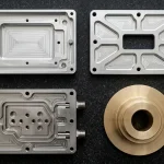
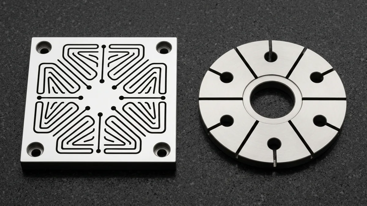
Fine-wire EDM threads Ø0.10–0.15 mm brass or tungsten wire through pre-drilled starter holes to cut distortion-free compliant mechanisms and internal profiles within ±0.005 mm (±0.0002″), as demonstrated by the hardened tool steel planar flexure stage with serpentine sub-millimeter through-slots and radially segmented spring collet ring shown here.
- Narrow Kerf & Elastic Hinge Webs: Cuts 0.13–0.20 mm (0.005″–0.008″) narrow through-slits and monolithic compliant flexure webs down to 0.15–0.25 mm thick without clamping distortion.
- Pre-Drilled Starter Hole Routing: Enclosed internal micro-slots and involute splines thread cleanly via Ø1.0–3.0 mm starter holes CNC-drilled before heat treatment (or Ø0.50–0.80 mm solid-carbide hard-drilled post-quench).
- Key Precision Applications: Monolithic XY optical flexure stages, radially segmented spring collet rings, internal involute splines, and surgical instrument jaw micro-slots.
EDM Processes & Precision Capabilities Matrix
| EDM Process & Fleet | Electrode / Wire & Envelope | Achievable Tolerance (mm / in) | Surface Finish (Ra μm / VDI 3400) | Recommended Application / When to Choose |
|---|---|---|---|---|
| Slow Wire EDM (Sodick 4-Axis X/Y/U/V) | Ø0.20–0.25 mm brass wire in deionized water; 400 × 300 × 250 mm, ±25° taper (3 units) | ±0.005 mm (±0.0002″) | Ra 0.2–0.4 μm (8–16 μin) | Hardened stamping punches, progressive blanking dies, extrusion dies, and through keyways |
| CNC Sinker EDM (Makino EDNC85) | Isostatic graphite, ETP copper & CuW electrodes in hydrocarbon oil; 800 × 500 × 350 mm (1 unit) | ±0.010 mm (±0.0004″) | Ra 0.4–0.8 μm (VDI 12–18; down to VDI 6–9) | Plastic injection mold cavities, deep blind ribs, sharp 90° blind corners, and VDI textures |
| Fine-Wire Micro-Slot & Flexure EDM | Ø0.10–0.15 mm fine brass / tungsten wire via pre-drilled starter holes; deionized water | ±0.005 mm (±0.0002″) | Ra 0.2–0.3 μm (8–12 μin) | Monolithic planar flexure stages, segmented spring collets, R0.07 mm internal splines, and micro-slots |
| Hardened & Exotic Alloy Erosion | Post-heat-treatment cutting up to 68 HRC (WC-Co 89–93 HRA); submerged thermal control | ±0.005–0.010 mm (±0.0002″–0.0004″) | Ra 0.2–0.8 μm (8–32 μin) | Tungsten carbide (WC-Co) wear plates, D2 / SKD11 / DC53 dies, Inconel 718, and Ti-6Al-4V hardware |
Metallurgy & Recast Layer (White Layer) Control
During spark erosion, localized plasma temperatures reach 8,000°C to 12,000°C, resolidifying a microscopic thermal film known as the recast white layer. For high-cycle stamping dies, aerospace flexures, and medical hardware, our in-house engineering team executes a 1 Rough Cut + 3–4 Skim Cuts protocol to hold the residual white layer ≤ 1–2 μm:
High-Energy Main Rough Cut
Progressive Trim & Bow Correction
3rd & 4th Micro-Energy Skims
Workable Materials: From Hardened Tool Steels to Superalloys
Because EDM removes metal via thermoelectric spark erosion rather than mechanical shear, material hardness never causes tool chatter, provided workpiece electrical resistivity is ≤ 100 Ω·cm (insulating plastics and oxide ceramics are excluded). We machine hardened steels up to 68 HRC after heat treatment to eliminate quench distortion:
Design for Manufacturability (DFM) Guidelines for EDM
Starter Hole Integration
Minimum Inside Radius
Flushing Channels
Wall Thickness & Ratio
| EDM Design Feature | Recommended Engineering Rule | Achievable Shop-Floor Limit | Spark Erosion Physics & Tooling Cost Impact |
|---|---|---|---|
| 1. Wire EDM Starter Holes | Pre-drill Ø1.0–3.0 mm starter hole before heat treatment (≥ 1.5 mm from finished profile wall) | Ø0.50–0.80 mm solid-carbide hard-drilled post-quench | Enables automatic submerged wire threading on Sodick ALN400Qs units without leaving lead-in witness marks on critical die walls. |
| 2. Minimum Internal Corner Radius | Specify R ≥ 0.13–0.15 mm (0.005″–0.006″) for standard Ø0.20 mm brass wire + spark overcut | R0.07 mm (Ø0.10 mm fine wire) / R0.03 mm (Sinker) | Standard Ø0.20–0.25 mm brass wire achieves 2×–3× higher area cutting rates than Ø0.10 mm micro-wire, substantially lowering cycle time. |
| 3. Recast (White Layer) Control | Call out 1 rough cut + 3–4 finishing skim cuts on fatigue-critical, medical, or sliding surfaces | Residual white layer ≤ 1–2 μm; Ra 0.2–0.4 μm (8–16 μin) | Progressive low-energy nanosecond skim passes strip thermally resolidified recast metal and eliminate wire-lag taper. |
| 4. Sinker EDM Cavity Flushing & Draft | Design 0.5°–1.0° base rib draft (plus 1.0°–1.5° per 0.025 mm VDI texture depth) or Ø1.0 mm vents | 0° vertical blind ribs up to 15:1 depth-to-width ratio | Evacuates eroded carbon/metal particles in deep blind ribs, preventing secondary side-arcing and molded part drag marks. |
| 5. Thin-Wall & Flexure Webs | Maintain minimum web thickness ≥ 0.25–0.40 mm on tall profiles (> 15 mm Z-height) | 0.15–0.20 mm on short planar flexures (≤ 15 mm height) | Zero mechanical cutting force prevents tool chatter, while symmetric skim sequencing balances internal residual stress release. |
| 6. Pre-Hardening & Stress Relief | Rough CNC machine + vacuum harden and double-temper (48–65 HRC) prior to final EDM | Up to 68 HRC tool steel & 89–93 HRA WC-Co carbide | Cutting final datums and profiles after heat treatment eliminates furnace quench distortion and locks in ±0.005 mm accuracy. |
| 7. Sinker Electrode Consolidation | Standardize blind pocket corner radii and rib pitch spacings across multi-cavity mold inserts | Custom CNC-milled isostatic graphite, ETP copper & CuW electrodes | Allows one multi-rib copper, graphite, or copper-tungsten (CuW) electrode to burn multiple identical features simultaneously. |
| 8. VDI 3400 Surface Callouts | Specify VDI 12 (Ra 0.40 μm) to VDI 27 (Ra 2.24 μm) directly on molded cavity sidewalls | VDI 6–9 (Ra 0.20–0.28 μm / 8–11 μin) mirror orbiting | Calibrated Makino CNC orbiting produces uniform isotropic matte release textures directly in the tank without manual stoning. |
What Is the Best Process Route for Hardened EDM Parts?
For hardened precision tooling, the optimal route is rough CNC machining, vacuum heat treatment, datum surface grinding, and final EDM: spark-eroding after hardening eliminates quench warpage while holding ±0.005 mm (±0.0002″). Review our steel heat treatment and distortion control guide and design for manufacturing (DFM) engineering guide for full routing details.
Rough Mill, Turn & Drill
Vacuum Harden & Temper
Datum Grind, Skim & Sink
Clean, Polish & Verify
Typical EDM Parts & Applications
Slow-wire, fine-wire micro-slot, and CNC sinker EDM are engineered for hardened alloys, sharp internal corners, and compliant micro-features that rotary cutters cannot reach:
Process Comparison: Wire EDM vs. Sinker EDM vs. CNC Milling
| Machining Factor | Slow Wire EDM (Sodick) | CNC Sinker EDM (Makino) | CNC Milling (3/4/5-Axis) | Precision Grinding |
|---|---|---|---|---|
| Material Hardness Limit | Conductive up to 68 HRC (WC-Co 93 HRA) | Conductive up to 68 HRC (WC-Co 93 HRA) | Standard ≤ 45 HRC (hard mill ≤ 55 HRC) | Hardened steels & carbides up to 68 HRC |
| Smallest Inside Radius | R0.07 mm (0.003″) through-corner | Near-sharp 90° blind (R ≥ 0.03 mm) | Limited by cutter radius (R ≥ 0.50 mm) | External steps & DIN 509 relief undercuts |
| Geometric Capability | 2D/4-axis through-profiles, ±25° tapers & micro-slots | 3D blind cavities, deep narrow ribs & hex sockets | Prismatic pockets, housings & open 3D surfaces | High-parallelism datum plates & OD journals |
| Mechanical Cutting Force | Zero (submerged spark erosion) | Zero (submerged spark erosion) | Moderate to high rotary shear force | Moderate tangential abrasive force |
| Achievable Tolerances | ±0.005 mm (±0.0002″) | ±0.010 mm (±0.0004″) | ±0.010–0.020 mm (ISO 2768-mK general) | ±0.005 mm (±0.0002″) |
| Recommended Application / When to Choose | Through-cut punches, dies, splines & planar flexures | Blind mold cavities, deep ribs & VDI 3400 textures | Un-hardened structural brackets, enclosures & manifolds | Mirror-flat datum plates & hardened bearing journals |
Metrology, CMM Inspection & Quality Control
Precision EDM tooling and compliant mechanisms require thermally stabilized dimensional verification. Our in-house 20°C ± 1°C climate-controlled metrology laboratory validates critical EDM features across every production batch:
Frequently Asked Questions (FAQ)
What is the minimum internal corner radius achievable with Wire EDM?
How does AS Prototypes minimize the recast layer (white layer) on EDM parts?
Can Electrical Discharge Machining process non-conductive materials like plastics or standard ceramics?
When should I choose Sinker EDM instead of CNC Milling?
What is the difference between wire EDM and sinker EDM?
Does EDM affect the properties of hardened steel?
Can wire EDM cut tungsten carbide?
What affects EDM cost and lead time?
Ready to Manufacture Precision EDM Parts & Tooling?
Upload your 3D CAD models (STEP, IGES, X_T) and 2D tolerance drawings for a comprehensive manufacturability review, starter-hole and electrode strategy, and custom quotation within 24 hours. Our in-house Sodick wire EDM and Makino sinker EDM shop holds ±0.005 mm (±0.0002″) critical slow-wire tolerances backed by 20°C ± 1°C Zeiss CMM inspection upon request.