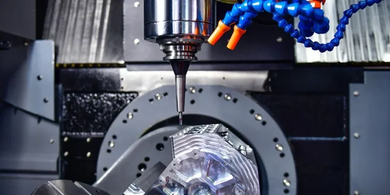
In mechanical manufacturing, CNC machining is widely adopted due to its high precision and efficiency. However, not all part designs can be seamlessly transitioned from drawing to production. Complex structures that appear perfectly reasonable during the design phase often pose severe challenges during actual machining.
To bridge the gap between design and manufacturing, this article explores common types of complex structures that increase CNC machining difficulty, outlines key design considerations, and provides practical DFM (Design for Manufacturability) optimization solutions based on a real-world case study.
1. Deep, Narrow Grooves and Structures with Small Clearances
Deep, narrow grooves and densely arranged thin-walled ribs are commonly found in parts like heat sinks and valve bodies. While their original design intent is usually to minimize weight or maximize heat dissipation area, they introduce significant hurdles in CNC machining:
- Tool Deflection and Vibration: Machining deep slots requires long-reach cutting tools. An excessive tool overhang-to-diameter ratio significantly reduces rigidity, leading to elastic deformation, tool chatter, dimensional deviations, and poor surface finishes.
- Poor Chip Evacuation: The extremely limited space within narrow slots prevents chips from evacuating smoothly. This often results in chip recutting, jams, or sudden tool breakage.
- Thermal Buildup: Coolant struggles to penetrate deep, narrow cavities. The resulting heat buildup accelerates tool wear and can cause thermal deformation of the workpiece, compromising final precision.

Optimization Methods
- Optimize Geometry: During the design phase, appropriately increase the slot width or reduce the slot depth to ensure the tool length-to-diameter ratio remains within a safe, rigid range.
- Enhance Rigidity: Utilize high-rigidity solid carbide tools or tapered neck cutters combined with optimized tool holding systems.
- Improve Cooling and Flushing: Increase coolant pressure, use through-spindle coolant (TSC), or design specialized chip evacuation channels.
- Staged Machining Strategy: When design modifications are restricted, employ a multi-stage strategy—performing rough machining with a larger tool to remove bulk material, followed by progressive finishing with a slender tool.
2. Structures with Small Radii and Incomplete Corner Clearing
Internal corner radii ($R$) designed too small are a primary reason parts require electric discharge machining (EDM) or manual benchwork, which dramatically drives up production costs.
- Rigidity vs. Diameter Conflict: Theoretically, small-diameter tools are required to resolve small $R$ corners. However, if the cavity is deep, the tool must be long. Standard machining limits prevent long tools from having a tiny diameter due to the high risk of snapping.
- Tool Path Residue: When the cutting tool radius is larger than the internal corner radius specified in the drawing, unmachined material will inevitably remain at the corner, creating a “dead zone.”
- Increased Process Steps: Corner clearing that cannot be completed via standard milling forces the part to be transferred to an EDM process, adding setup errors, extra tooling, and extending the overall manufacturing cycle.

Optimization Methods
- Relax Internal Radii: Within design constraints, increase the internal corner radii as much as possible. Ideally, the radius should be slightly larger than the radius of a standard milling cutter to allow smooth, single-pass corner clearing.
- Optimize Feed Paths: Use helical or trochoidal arc feed patterns at corners to avoid sudden directional changes that trigger tool vibration and gouging.
- Process Notches: Where sharp internal corners are functionally mandatory, design relief notches (dog-bone corners) or split the structure into sub-assemblies to convert complex internal features into easily machinable external ones.
3. Thin-Walled Structures
Thin-walled parts are highly desirable for aerospace and lightweight automotive applications, but their lack of structural mass introduces severe stability issues during cutting:
- Poor Structural Rigidity: When walls are too thin, the workpiece lacks the structural strength to resist cutting forces, leading to severe elastic deflection away from the tool.
- Clamping Complexities: Excessive clamping force from traditional vises easily warps thin-walled parts, while insufficient force fails to secure the part safely against high-speed cutting forces.
- Resonance and Chatter: Thin-walled structures have low natural frequencies. They easily resonate with the spindle speed and cutting frequencies, leaving heavy chatter marks on the surface.

Optimization Methods
- Temporary Sacrificial Supports: Add structural ribs or temporary supports during the design phase that reinforce the wall during machining and are removed in the final operation.
- Advanced Workholding: Utilize specialized fixtures such as vacuum chucks, custom soft jaws, or low-melting-point alloy fillers to damp vibrations and secure the walls uniformly.
- Dynamic Milling Paths: Separate roughing and finishing operations completely. During finishing, adopt a “light-cut, high-speed” strategy (high spindle speeds, rapid feed rates, and small radial depths of cut) to minimize cutting forces.
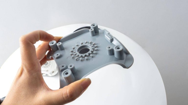
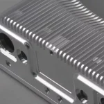
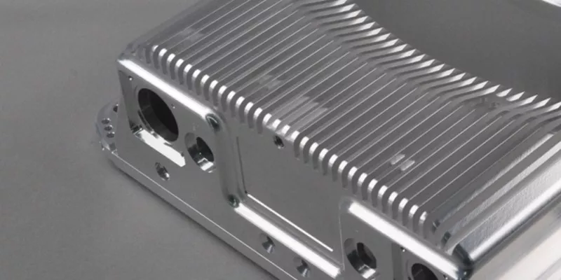
Case Study: Machining Optimization of an Electric Truck Heat Sink Housing
To demonstrate how DFM engineering reduces CNC machining difficulty, let us analyze a real production project managed by AS Prototypes: a heat sink housing for an electric truck powertrain.
- Material: ADC12 Aluminum Alloy
- Dimensions: Approximately 159 x 135 x 67 mm
- Design Intent: High-efficiency heat dissipation featuring a large-area, densely packed fin structure with deep grooves.
Initial Manufacturing Bottlenecks
Upon receiving the original design drawings, our engineering team identified three critical issues that severely hindered production efficiency and risked part failure:
- Unreasonable Deep-Groove Ratio: The width between the cooling fins was only 3.2 mm, while the groove depth reached 28 mm. This required a 3 mm diameter milling cutter with an overhang exceeding 29 mm—a length-to-diameter ratio of nearly 10:1. The tool lacked all necessary rigidity, causing heavy vibration, frequent breakage, and making it impossible to achieve the required Ra 1.6 surface roughness.

- Impractical Cavity Corner Radii: The internal cavity had a depth of 28 mm but specified an R0.5 radius at the bottom corners. While a 3 mm cutter was required to reach the depth, its own corner radius (R1.5) left substantial unmachined material at the bottom. Under the original design, this forced an expensive secondary EDM process.

- Excessively Fragile Wall Thickness: The heat sink fins were designed with a wall thickness of only 1.2 mm at a height of 25 mm. Initial tests showed heavy tool deflection and severe dimensional instability.

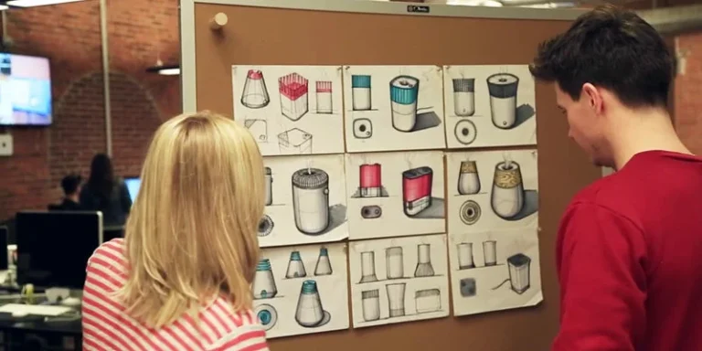
DFM Adjustments & Implementation
AS Prototypes collaborated closely with the client’s design team to implement the following structural optimizations without impacting the part’s core thermal performance:
- Optimization 1: Stepped Fin Design The original 28 mm deep straight groove was modified into a stepped configuration. The bottom 15 mm section retained the 3 mm width, while the upper 13 mm section was widened to 6.2 mm. This allowed us to deploy a rigid 6 mm tool to rapidly bulk out the top section, leaving only the shallow bottom section for the slender 3 mm tool. Cutting parameters increased more than threefold, reducing tool wear significantly.

- Optimization 2: Radius Standardization to Eliminate EDM Engineering analysis confirmed that increasing the cavity bottom corner radius from R0.5 to R1.55 had no impact on assembly. By making this change, the entire cavity could be machined cleanly in a single setup using standard 3 mm and 6 mm flat-bottom end mills, completely eliminating the 2.5-hour EDM process.

- Optimization 3: Controlled Wall Thickening The fin wall thickness was adjusted from 1.2 mm to 2.5 mm. This minor change drastically increased structural rigidity, suppressed tool chatter, and successfully stabilized wall thickness tolerances within +/-0.05 mm.

Comparison of Machining Data Before & After Optimization
| Item | Before Optimization | After Optimization | Improvement |
| Single-Part Machining Time | 6.5 hours | 3.2 hours | 51% reduction |
| Tool consumption | 8–10 tools/part | 4–6 tools/part | 40% reduction |
| Secondary EDM Process | Retained | Eliminated | 2.5 hours saved |
| Surface Roughness Quality | Ra 1.6–3.2 | Ra 0.8–1.2 | Significant improvement |

Key DFM Recommendations for Complex Parts
To minimize CNC machining difficulty, reduce production costs, and ensure part consistency, we recommend adhering to the following manufacturing guidelines during your initial design phases:
- Evaluate Tool Accessibility First: Always calculate the length-to-diameter ratio of the tools required for your deep cavities. As a general rule, try to keep slot and hole depths within 5 times the tool diameter.
- Design for Standard Tooling Radii: Match your internal fillets to standard end mill dimensions, adding a small clearance margin (e.g., specifying an R3.2 corner for a 6 mm cutter) to allow smooth tool transitions without stalling in corners.
- Balance Fin Geometry: When designing cooling fins or grilles, consider stepped profiles if deep pockets are necessary. Increasing wall thickness slightly yields massive gains in machining speed, tool lifespan, and surface quality.
AS Prototypes’ Expertise in Complex CNC Machining
With extensive experience handling complex geometries, strict tolerances, and challenging materials, AS Prototypes offers optimized CNC machining solutions tailored for demanding designs involving deep cavities, thin walls, and tight internal radii.
By integrating comprehensive DFM feedback early in the engineering phase with advanced multi-axis machining strategies, we help clients worldwide reduce production risks, slash manufacturing costs, and achieve consistent, high-precision results.