As a designer, your goal is to create functional and aesthetically pleasing products. However, translating these designs into manufacturable parts can sometimes lead to challenges, particularly in terms of cost. Often, a design that looks great on paper may result in high manufacturing expenses if not initially conceived with production methods in mind. This is especially true for CNC aluminum parts. To help you save money during the prototyping stage, here are a few tips to consider before finalizing your design.
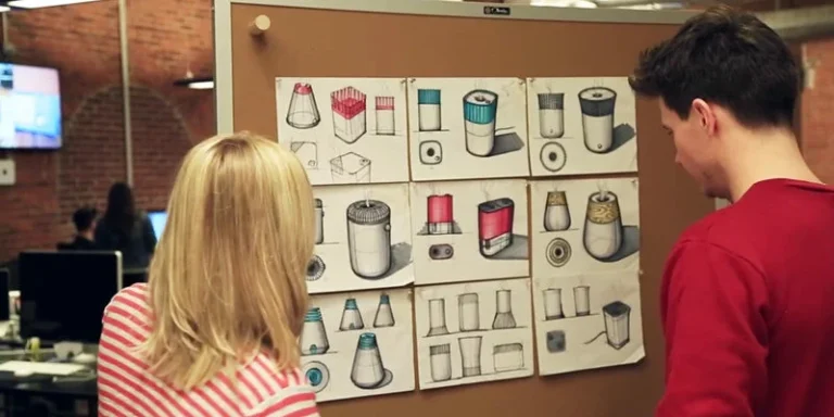
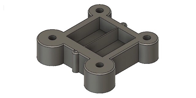
Let’s use an example of an enclosure model to illustrate these tips. This simple device features a panel that fits into a square hole and is secured with four screws, as shown in the image below.
Tip 1. Check The Holes
First. Long Threading
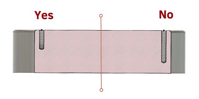
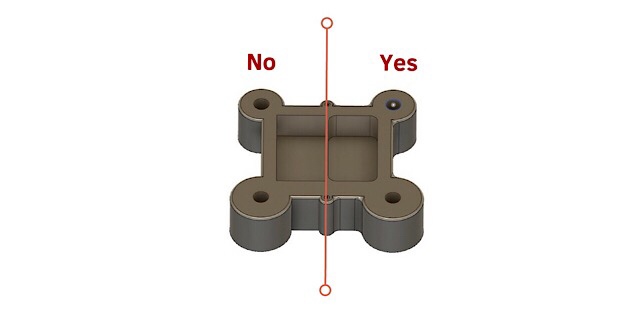
There’s a common misconception that the longer the thread and screw, the stronger the hold. However, this isn’t true. When you calculate the distribution of force, you’ll find that the first two or three teeth of the thread bear 80% of the load. This means that creating long holes for long bolts is unnecessary.
Second. Blind holes
When designing a blind and threaded hole, it’s important to leave some space free of threads near the bottom—at least more than two thread pitches. This is because the threading tool has two distinct zones. The first zone, known as the “cutting in” zone, starts with a diameter equal to the thread’s inner diameter and gradually increases to the outer diameter, cutting a bit more with each turn. The second zone is for calibration, ensuring the thread is precise. This additional space allows the tool to fully cut and calibrate the last turns of the thread.
Third. Look for deep holes
The general guideline for threaded holes is to keep the depth not much more than three times the diameter. This is because deeper holes require longer drills, which are less rigid and more prone to deviating from the axis, resulting in lower-quality holes. For very deep holes, a gun drill might be used, which can create holes of virtually any length but at a higher cost.
If your design includes deep holes, it might be worth reconsidering their dimensions. For instance, increasing the diameter of the hole for the prototype phase could help you avoid the need for specialized, expensive tools while still maintaining the part’s main functional features.
Tip 2. Check The Pockets
First. 90-degree angles
When designing parts with pockets, many designers aim for 90-degree angles. However, most prototype parts are machined using CNC milling centers, which use cylindrical revolving tools to cut material. These tools can’t create perfect 90-degree internal angles in confined spaces. To achieve such angles, the manufacturer would need to use a shaping machine to remove the fillet, which adds unnecessary complexity and cost.
In many cases, a sharp 90-degree angle isn’t essential. Allowing the natural fillet created by the milling tool can simplify the manufacturing process and reduce costs. However, if the design requires fitting a corresponding part into the slot, consider adding matching fillets to the inserted part. This adjustment doesn’t complicate or lengthen the CNC programming.
If matching fillets on the inserted part isn’t an option, consider creating a cylindrical cutout at least one-third the depth of the pocket. This approach allows the manufacturer to mill the part efficiently while still accommodating the square part. See the illustration below for reference.
Second. Avoid deep pockets
One of our team members encountered a significant challenge early in their machining career. They were working on a large turbine blade and needed to machine a section of the airfoil. Unfortunately, the stock they chose was too small, so the jigs were positioned right at the edge of the airfoil. Given the size and curvature of the airfoil, the pocket in the middle was quite deep. They couldn’t move the tool outside the airfoil’s perimeter without risking a collision with the jigs, which would have been catastrophic.
As a result, they had to use a 150 mm long, 10 mm diameter mill. With such a long and thin tool, they could only set the cutting depth to 0.3 mm or less, or the mill would snap like a twig. They ended up breaking two or three mills while machining those airfoils.
The lesson here is to avoid designing small and deep pockets whenever possible. If you can’t avoid them, be prepared for the potential cost of breaking and replacing tools.
Third. Avoid thin walls
Thin walls are every manufacturer’s enemy. Machining generates significant force and heat, which can easily damage thin walls. If your design includes thin elements to reduce weight, consider making them thicker and drilling holes to achieve the weight reduction. Alternatively, you can design the thin walls to gradually thicken as they approach their base. This approach can help maintain structural integrity while still achieving your design goals.
Tip 3. Check The Part Requirements
Many designers believe that the more precise the part or the finer the surface finish, the better. This is a common misconception. While ground and polished parts do look impressive, shiny, and are less prone to corrosion, manufacturing them is often a lengthy and expensive process. This is why different parts have varying tolerances and surface finish requirements. It’s important to balance the need for precision and aesthetics with the practicalities of manufacturing costs and time.
First. Check the surface finish
In manufacturing engineering, part surfaces are categorized into two types: functional and secondary. Functional surfaces are crucial for the part’s operation within a mechanism. For instance, the inner central hole of a car wheel is a functional surface because it fits onto the chassis. These surfaces are typically the most precise and finely finished areas of the part, as they bear all the loads and perform the essential functions.
Conversely, secondary surfaces act as intermediaries between functional surfaces or contribute to the part’s structural integrity by adding thickness. Therefore, it is unnecessary to finely finish all surfaces, as doing so would significantly increase the cost of the part without providing additional benefits.
Second. Check the tolerances
The key takeaway here is efficiency in manufacturing. There’s no need to grind and finish all surfaces to a 0.005 mm precision if such precision won’t be utilized. When designing a part, the primary step should be to identify its functional surfaces and concentrate efforts on those areas.
In Conclusion
There are countless tips for reducing machining costs. Some involve correct size positioning in the part drawing, while others focus on selecting or creating surfaces to secure the part during machining. There are also methods to enhance machining efficiency without altering the design, along with various other complex strategies. However, the product designer doesn’t need to master all these techniques—that’s the role of a manufacturing engineer. But if your manufacturing engineer works for an outsourcing company, you’ll need to assume part of his/her responsibilities during the design stage. By following these tips, you can significantly reduce the machining time of your prototype.