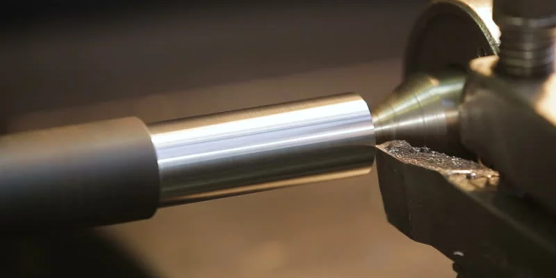
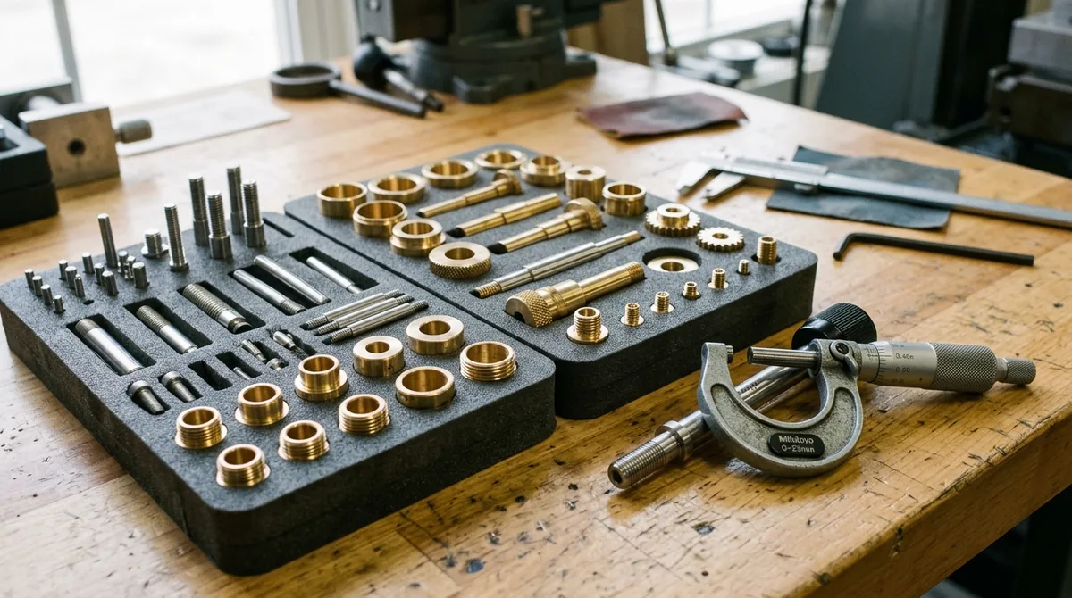
In modern high-performance manufacturing, precision CNC turning has evolved far beyond rudimentary single-point cylindrical cutting on basic 2-axis lathes. Advanced mechanical assemblies—such as micro-fluidic medical cannulas, high-pressure aerospace poppet valves, optical sensor housings, and precision transmission shafts—require diametric tolerances down to +/-0.005mm, total radial runout within 0.003mm, and high-precision optical surface finishes (Ra ≤ 0.2 μm). Delivering these demanding geometric specifications requires advanced machine tool kinematics, spanning multi-axis CNC turning centers with driven live tooling to high-precision Swiss-type machining with sliding headstocks. This comprehensive engineering guide examines lathe kinematic architectures, deflection mechanics, finish hard turning, and metrology standards for precision turned components.
1. Lathe Kinematics: Fixed-Headstock vs. Swiss-Type Sliding Headstock
The defining technical factor governing cylindrical accuracy and surface finish is workpiece deflection under tool cutting forces. According to classical cantilever beam deflection theory:
δ = (Fc × L³) / (3 × E × I)
Where δ represents radial bar deflection, Fc is the radial cutting force, L is the unsupported overhang length, E is material elastic modulus, and I is the area moment of inertia. Notice that deflection scales cubically with unsupported length (L³). In conventional fixed-headstock lathes, when the length-to-diameter ratio exceeds L/D > 4:1, cutting pressure pushes the bar radially outward, causing severe dimensional tapering, chatter harmonics, and catastrophic tool chipping unless tailstocks or steady rests are engaged.
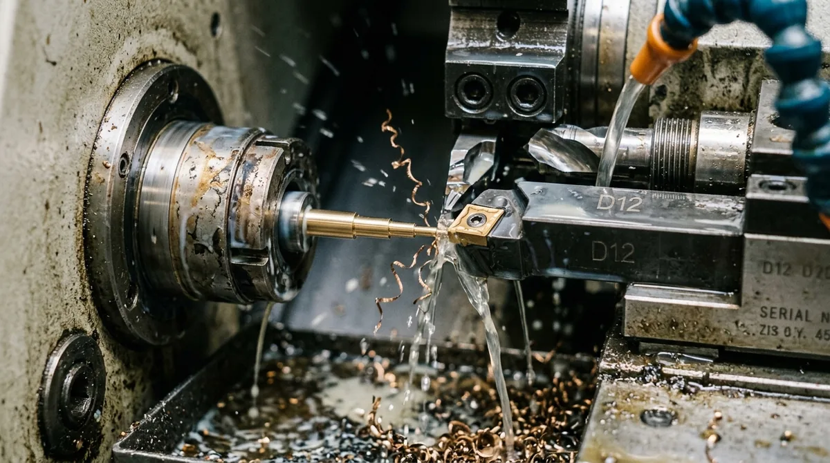
The Swiss Machining Solution: In a Swiss-type sliding headstock lathe, the raw bar stock is clamped in a guide collet and advanced continuously through an ultra-rigid carbide guide bushing. The cutting tool is positioned immediately adjacent to the guide bushing face (within 1mm to 2mm). Because the unsupported distance (L) remains practically zero regardless of part length, radial bar deflection is virtually eliminated. This allows machinists to turn slender shafts, miniature pins, and medical bone screws with L/D ratios of 20:1 or greater while holding diametric tolerances within +/-0.002mm.
In a conventional lathe, the workpiece is clamped in a chuck while the tool moves along the Z-axis, making parts with length-to-diameter ratios greater than 4:1 prone to deflection. In a Swiss-type lathe, the bar stock advances through a high-precision carbide guide bushing with the tool cutting within 1mm to 2mm of the support, eliminating bar deflection and allowing L/D ratios of 20:1 or more with high-precision repeatability (±0.005mm).
Finish hard turning with PCBN or ceramic inserts should be selected when machining hardened steels (58 to 65 HRC) that feature multi-step profiles, contours, or internal bores. It allows complete profiling in a single setup, achieves Ra 0.1 to 0.2 µm surface finish, operates dry without coolant sludge waste, and significantly reduces cycle times compared to grinding.
Mill-turn centers integrate main and sub-spindles with live milling tooling. By transferring the workpiece between synchronized spindles on-the-fly and completing all turning, cross-milling, and reverse-end operations in a single clamping cycle, datum transfer errors are eliminated, holding concentricity within 0.003mm TIR.
Partner with AS Prototypes for Precision CNC Turning Services
Request an Instant RFQ for High-Precision Turned Components
From micro-machined Swiss turned shafts and medical implant hardware to multi-axis mill-turned prismatic aerospace valves, AS Prototypes delivers precision turning tolerances down to +/-0.005mm. Upload your 2D engineering drawings and 3D CAD files (STEP, IGES) for automated DFM analysis, material recommendations, and rapid quote turnaround.
Get an Instant RFQ & DFM Review →