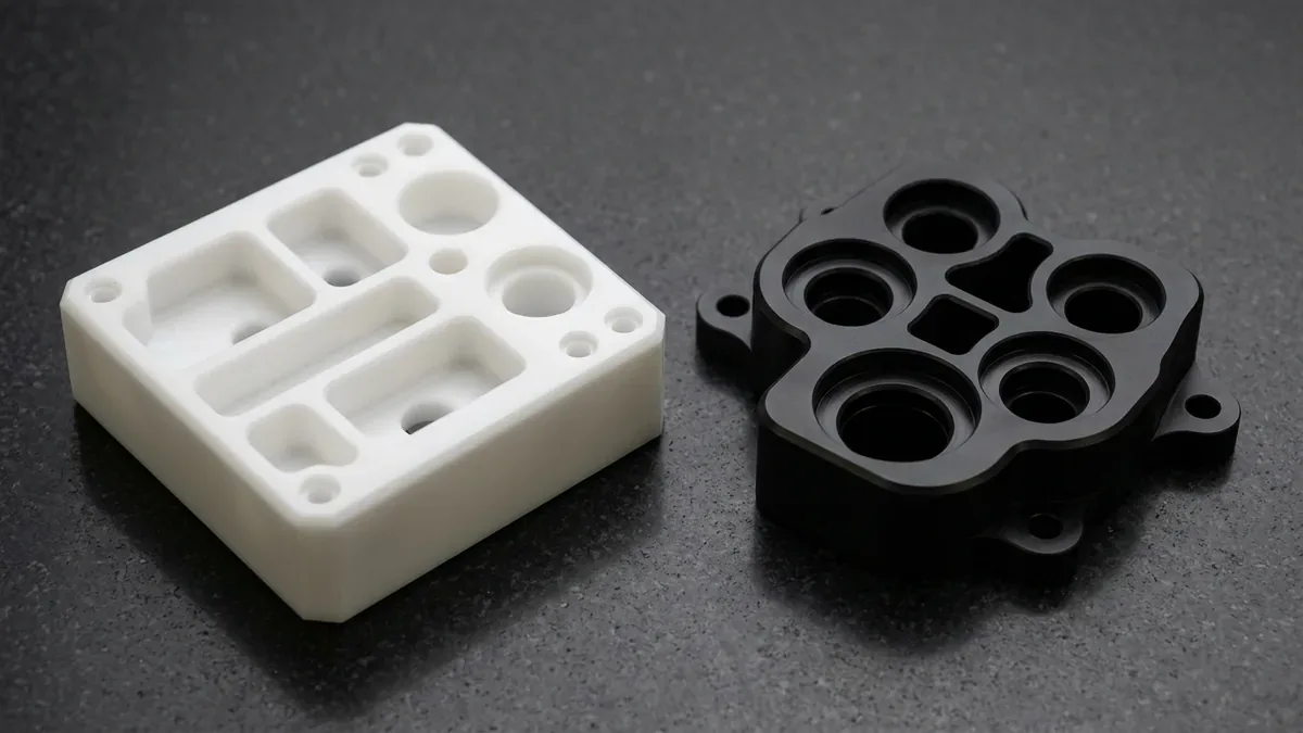
Polyoxymethylene (POM), widely known as acetal and marketed under trade names including Delrin® (homopolymer) and Hostaform® / Ultraform® (copolymer), represents one of the most reliable engineering thermoplastics for high-precision CNC manufacturing. Characterized by high mechanical strength, low friction coefficient (0.20–0.35 static), minimal moisture absorption (<0.2% over 24 hours), and excellent machinability, POM is widely utilized to replace non-ferrous metals in precision components such as gears, bushings, fluid manifolds, and valve bodies. However, achieving tight engineering tolerances—such as ISO 2768-mK general tolerances or drawing-specified precision tolerances—requires strict process control over internal stress relief, thermal expansion dissipation, and tool rake geometry.
Executive Summary & Engineering Takeaways (BLUF)
- Core Focus & DFM Scope: Actionable shop-floor engineering guidelines for CNC Machining POM Plastic, covering material selection, geometric tolerancing, and defect prevention.
- Thermal & Stress Management: Pre-machining and intermediate stress-relief annealing at 130°C–140°C (with slow 5°C–10°C/hr cooling) prevents post-machining warpage caused by POM’s high thermal expansion (100 × 10-6 K-1).
- Tooling & Surface Integrity: High-rake (15°–25°) polished single-flute or two-flute uncoated carbide cutters paired with dry cold-air vortex cooling deliver burr-free edges and Ra 0.4–0.8 µm (16–32 µin) surface finishes per ISO 4287 / ASME B46.1.
- Achievable Tolerance Envelope: General features conform to ISO 2768-mK; critical bearing bores and mating datums hold ±0.010 mm to ±0.020 mm (±0.0004″ to ±0.0008″) after a 2–4 hour thermal soak at 20°C ± 1°C.
- Ex-Factory Turnaround: 4 to 8 business days for as-machined POM rapid prototypes; 7 to 12 business days for stress-relieved precision production batches (excluding 3–5 days air transit).
Article Engineering Navigation
- 1. POM-C (Copolymer) vs. POM-H (Homopolymer / Delrin®): Engineering Material Selection
- 2. Thermal Expansion Dynamics and Stress-Relief Annealing Protocols
- 3. Tooling Geometry, Speeds, Feeds, and Coolant Strategies
- 4. Workholding and Fixturing: Preventing Clamping Distortion
- 5. Dimensional Metrology, Deburring, and Quality Assurance
- 6. Why Do Precision Machined Components Fail Tight Tolerances in Production, and How Do You Prevent It?
- 7. Technical Engineering FAQ
1. POM-C (Copolymer) vs. POM-H (Homopolymer / Delrin®): Engineering Material Selection
A frequent root cause of premature failure in machined acetal parts is improper grade selection between POM-C (Acetal Copolymer) and POM-H (Acetal Homopolymer, commonly DuPont Delrin®). While both variants share similar basic chemistry, their crystalline morphology creates distinct mechanical and machining behaviors:
- Centerline Porosity Risk in POM-H: Because POM-H has a higher degree of crystallinity, it experiences greater volumetric contraction during extrusion cooling. In thick cross-sections (diameters or plate thicknesses exceeding 25mm / 1.0 inch), homopolymer stock frequently develops microscopic voids along the extruded centerline. When machining high-pressure fluid manifolds, valve seats, or medical components, this centerline porosity can cause through-wall leaks or localized crack propagation. POM-C, by contrast, exhibits virtually zero centerline porosity, making it the mandatory standard for pressure-tight applications.
- Mechanical Strength & Fatigue: POM-H delivers approximately 10% to 15% higher tensile strength (71 MPa vs 65 MPa) and higher flexural modulus (3.2 GPa vs 2.8 GPa) than POM-C. It provides superior surface hardness and creep resistance under sustained mechanical loads, making it ideal for precision spur gears, snap-fits, and wear plates.
- Chemical & Thermal Resistance: POM-C provides superior long-term resistance to hot water, steam, and strong alkaline chemicals (pH 4 to 14). In contrast, POM-H degrades rapidly in alkaline environments (pH > 9) and hot water exposure.
| Engineering Parameter | POM-C (Acetal Copolymer) | POM-H (Homopolymer / Delrin®) | DFM Selection Verdict |
|---|---|---|---|
| Tensile Strength & Modulus | 65 MPa (9.4 ksi) / 2.8 GPa | 71 MPa (10.3 ksi) / 3.2 GPa | Select POM-H for high-load gears & snap-fits |
| Centerline Porosity Risk | Virtually Zero (Homogeneous Core) | Moderate in Stock > 25 mm (1.0″) | Mandatory POM-C for pressure-tight fluid manifolds |
| Chemical & pH Resistance | pH 4–14 (Hot Water & Alkaline Safe) | pH 4–9 (Degrades in Strong Alkalis) | Select POM-C for CIP/SIP washdown & valve bodies |
| CNC Milling Speed & Tolerance | 250–450 m/min | ±0.020 mm (±0.0008″) | 250–400 m/min | ±0.015 mm (±0.0006″) | Both require stress-relief annealing at 130–140°C |
2. Thermal Expansion Dynamics and Stress-Relief Annealing Protocols
The primary barrier to holding ±0.010 mm to ±0.020 mm tolerances in acetal components is post-machining dimensional distortion caused by residual extrusion stress and thermal expansion. The Coefficient of Linear Thermal Expansion (CLTE) of POM is approximately 100 × 10-6 K-1—roughly 4.3 times greater than 6061-T6 aluminum and 6 times greater than 304 stainless steel. Coupled with low thermal conductivity (0.31 W/m·K), heat generated during heavy cutting remains trapped in the part, causing significant thermal dilation.
To eliminate internal stress before and during machining, AS Prototypes deploys an industrial stress-relief annealing process:
- Pre-Machining Annealing: Raw billets are heated in an air-circulating oven at a controlled ramp rate of 10°C to 15°C per hour up to 130°C–140°C (well below the 165°C melting point). The material is soaked for 1 hour per 25mm of cross-sectional thickness to homogenize crystalline structure.
- Slow Controlled Cooling: The oven is cooled at a rate not exceeding 5°C to 10°C per hour until the chamber reaches 40°C before removing the stock. Rapid cooling reintroduces thermal tension, defeating the process.
- Intermediate Annealing for Ultra-Tight Tolerances: For complex geometries with asymmetric pockets, thin ribs, or tight bore requirements, parts undergo a two-stage machining workflow: roughing within 0.5mm–1.0mm of final dimensions, followed by intermediate stress-relief annealing at 110°C, and a final finish pass at high surface speeds and light depths of cut.
3. Tooling Geometry, Speeds, Feeds, and Coolant Strategies
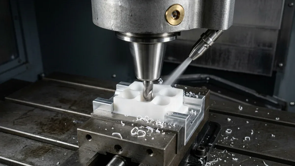
Machining POM requires dedicated plastic-cutting tool geometries. Standard end mills designed for steel or aluminum possess negative or small positive rake angles, which plow and compress POM rather than shearing it cleanly, causing material smearing and heavy burr formation.
Optimal tool configuration includes:
- Rake & Relief Angles: High positive rake angles (15° to 25°) and generous relief angles (10° to 15°) to minimize flank rubbing and reduce frictional heat.
- Flute Geometry: Polished 1-flute or 2-flute solid carbide cutters with mirror-finished flutes. Single-flute up-cut spiral cutters provide maximum chip clearance volume, preventing continuous ribbon chips from wrapping around the spinning spindle.
- Cutting Edges: Uncoated, razor-sharp ground cutting edges. Avoid thick PVD/CVD wear coatings (such as AlTiN) which round the cutting edge radius and induce frictional heat.
Our engineers prioritize dry machining utilizing high-pressure cold-air guns (vortex tubes). Cold air maintains tool zone temperatures below 50°C while instantly evacuating continuous plastic swarf from the cut zone. If liquid flood coolant is required for deep-pocket clearing, water-soluble synthetic fluids are employed and parts are thoroughly degreased immediately after machining to prevent environmental stress cracking.
4. Workholding and Fixturing: Preventing Clamping Distortion
Because POM exhibits an elastic modulus of only 2.8 to 3.2 GPa (compared to ~70 GPa for aluminum alloys), conventional high-torque metal vise clamping will deform the raw stock elastically during fixturing. Once the part is machined flat and unfastened from the vise, the internal elastic rebound causes the component to spring back into an out-of-square, bowed, or twisted profile.
To eliminate clamping-induced distortion, our CNC milling and multi-axis turning cells utilize specialized workholding techniques:
- Custom Soft Aluminum Pie Jaws: Machined with negative profile cavities that cradle the exact contours of the POM workpiece, distributing clamping pressure across maximum surface area rather than point loads.
- Calibrated Low-Torque Clamping: Vises and hydraulic workholding are fitted with digital torque limiters calibrated to prevent elastic deflection exceeding 0.005 mm.
- Vacuum Fixturing for Thin Plates: For wide, thin-walled POM cover plates, vacuum fixture beds eliminate mechanical jaw pressure entirely, holding the workpiece completely flat without inducing localized stresses.
5. Dimensional Metrology, Deburring, and Quality Assurance
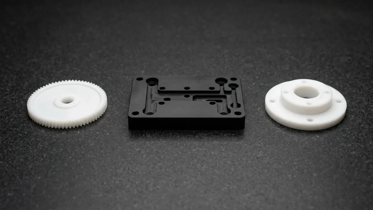
Due to POM’s high ductility, exit cuts frequently produce flexible micro-burrs along sharp edges, especially when tool edges begin to dull. AS Prototypes employs precision microscopic hand-deburring with specialized curved scalpel edges and high-speed rotary abrasive brushes to ensure burr-free chamfers without compromising edge sharpness.
For cylindrical shafts, bushings, and lead screws produced on our CNC turning equipment, parts are transferred to our climate-controlled quality assurance laboratory (stabilized at 20°C ± 1°C). Components undergo thermal soak for 2 to 4 hours to equalize core temperatures prior to final inspection using 2.5D optical vision measuring systems (VMS), calibrated Go/No-Go plug gauges, and on-demand Zeiss bridge coordinate measuring machines (CMM), ensuring strict compliance with ISO 2768-mK or customer-specific GD&T callouts down to ±0.010 mm to ±0.020 mm.
6. Why Do Precision Machined Components Fail Tight Tolerances in Production, and How Do You Prevent It?
Maintaining repeatable accuracy in precision Delrin (POM) plastic CNC machining requires controlling radial tool deflection, internal residual stress relaxation, and thermal expansion drift across multi-axis setups. While general unmated features reliably conform to ISO 2768-mK, holding critical mating bores and datum surfaces within ±0.010 mm to ±0.020 mm (±0.0004″ to ±0.0008″) demands staged roughing-to-finishing stress relief and low-pressure workholding.
Shop-Floor Quantitative Derivation: Cantilever Tool Deflection & Thermal Drift Compensation
In our Shenzhen CNC machine shop, preventing wall taper and bore bell-mouthing in precision Delrin (POM) plastic CNC machining begins with calculating cantilever end-mill deflection (δ) before releasing G-code to the spindle. Modeled as a cylindrical carbide beam of diameter D and stickout length L subjected to radial cutting force Fr, tool deflection follows the fourth-power stiffness law:
δ = (64 × Fr × L³) / (3 × π × E × D⁴)
For a solid carbide end mill (E = 600 GPa / 87,000 ksi) with diameter D = 8.0 mm (0.315″), stickout L = 36 mm (4.5×D), and radial cutting load Fr = 180 N (40.5 lbf), the resulting deflection is δ = (64 × 180 × 36³) / (3 × 3.1416 × 600,000 × 4,096) = 0.0232 mm (0.00091″)—instantly consuming a ±0.010 mm (±0.0004″) drawing tolerance! By stepping up to a D = 10.0 mm (0.394″) corner-radius tool and reducing stickout to L = 28 mm (2.8×D) with a 0.15 mm (0.006″) semi-finishing spring pass (Fr = 45 N), radial deflection drops to δ = 0.0011 mm (0.00004″), locking true position and cylindricity well within print limits.
Step-by-Step Shop-Floor Execution & Quality Protocol
To bridge CAD intent with repeatable shop-floor delivery, our engineering team enforces a four-stage execution workflow across every prototype and low-volume production batch:
- Step 1: Datum Hierarchy & 3/4/5-Axis Workholding Design: Align primary, secondary, and tertiary GD&T datums (A-B-C) with precision Kurt vises, custom-contoured 6061 aluminum soft jaws, or zero-point pneumatic pallets to minimize re-clamping datum shift.
- Step 2: Roughing & Intermediate Annealing Stabilization: Execute high-efficiency roughing leaving 0.50 to 1.00 mm (0.020″ to 0.040″) uniform stock, followed by intermediate oven annealing at 110°C–130°C to release extruded-billet internal stress.
- Step 3: On-Machine Probing & Climate-Controlled Finishing: Re-probe work coordinate offsets via infrared spindle touch probes in a 20°C (68°F) shop environment, then execute climb-milling finish passes to achieve Ra 0.4–0.8 μm (16–32 μin).
- Step 4: Thermal Soak & Optical / CMM Metrology: Soak finished POM components for 2 to 4 hours at 20°C ± 1°C prior to non-contact 2.5D optical vision inspection, calibrated Go/No-Go plug gauging, and on-demand Zeiss CMM verification.
Shop-Floor Defect Troubleshooting & Corrective Action Matrix
When evaluating part geometry during pre-production DFM review, our manufacturing engineers screen for the following failure modes and apply proven corrective controls:
| Defect / Symptom | Physical Root Cause | Shop-Floor Corrective Action | Recommended DFM Spec Limit |
|---|---|---|---|
| Thin-Wall Warpage & Bowing | Asymmetric removal of extruded outer skin releasing internal residual stress or excessive clamping jaw pressure | Alternate roughing passes symmetrically across both sides, leave 0.5 mm stock for intermediate annealing, and finish-mill in low-pressure contoured soft jaws. | Flatness ≤ 0.03 mm / 100 mm |
| Deep Pocket Wall Taper & Chatter | Tool stickout exceeding L/D > 4:1 causing harmonic regeneration and radial tool push-off | Maximize internal corner radii (R ≥ 1/3 cavity depth) to permit larger-diameter stubby carbide tools and apply variable-helix climb milling. | Optimal pocket L/D ≤ 4:1 |
| Bore Out-of-Roundness (3-Lobing) | Three-jaw chuck clamping distortion on thin-walled rings or thermal spindle growth | Switch to full-wrap pie jaws or vacuum fixtures, execute a zero-offset spring boring pass, and verify with air/plug gauges before unclamping. | Cylindricity ≤ 0.008 mm |
| Centerline Porosity & Seepage | Core volumetric shrinkage voids along the extrusion axis of thick POM-H (Delrin®) stock (> 25 mm) | Switch to homogeneous POM-C copolymer for thick cross-sections and validate fluid manifolds via 3.5–6.0 bar pneumatic pressure decay testing. | Mandate POM-C for stock > 25 mm |
Engineering Trade-Offs: When NOT to Over-Specify
When to Avoid Over-Specifying (Engineering Cost-Tolerance Trade-Offs): Never apply blanket ±0.010 mm (±0.0004″) tolerances or simultaneous 5-axis callouts across non-mating exterior surfaces and clearance brackets on polymer parts. Tightening a non-critical feature from standard ISO 2768-mK (±0.10 to ±0.20 mm) to ±0.010 mm increases cycle time and inspection overhead by 2.0× to 3.5× due to mandatory semi-finishing passes, thermal soak cycles, and CMM verification. Reserve tight tolerances strictly for functional bearing journals, dowel pins, and sealing faces, while letting 3-axis and 4-axis VMCs handle prismatic geometry efficiently.
🔗 Related CNC DFM & Metrology Engineering Guides:
To further optimize cycle time and dimensional stability in precision Delrin (POM) plastic CNC machining, combine proper internal corner relief with datum-based coordinate inspection. Consult our shop-floor engineering guides on Maintaining Dimensional Stability in Thin-Wall Machining, Eliminating Sharp Internal Corners & Tool Deflection, and Precision CMM Metrology & GD&T Verification.
7. Technical Engineering FAQ
POM-C (acetal copolymer) offers superior resistance to hot water, steam, and strong alkaline chemicals (pH 4-14) with virtually zero centerline porosity in thick cross-sections, making it ideal for fluid manifolds and valve blocks. POM-H (acetal homopolymer, DuPont Delrin) delivers 10% to 15% higher mechanical strength, stiffness, and fatigue resistance, but exhibits centerline porosity in billets thicker than 25mm and degrades in alkaline environments.
POM has a high thermal expansion coefficient (approx. 100 × 10-6 K-1, roughly 4 to 5 times higher than aluminum) and holds internal extrusion stresses. Machining releases these stresses and introduces localized heat. Deformation is prevented by pre-machining annealing at 130°C–140°C with slow furnace cooling (5°C to 10°C/hr), using polished sharp single-flute or two-flute cutters with high positive rake angles, and using soft vise jaws with controlled light clamping torque.
Yes. With proper stress-relief annealing cycles, temperature stabilization in a 20°C ± 1°C metrology laboratory, and specialized tooling, AS Prototypes routinely achieves ±0.010 mm to ±0.020 mm tolerances on precision POM features, fully compliant with ISO 2768-mK general tolerances and drawing-specified precision tolerances.
Partner with Our Precision CNC Machining & Engineering Team
Eliminate tool deflection, residual stress distortion, and tolerance stack-up risks before production begins. Upload your 3D CAD files (STEP/IGES) and 2D GD&T drawings for a comprehensive shop-floor DFM review and custom quotation.
Upload 3D CAD for Engineering DFM & RFQ