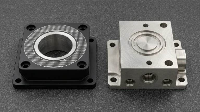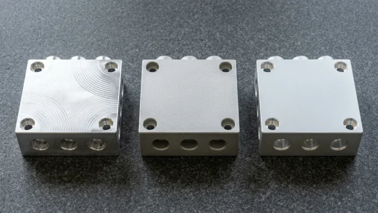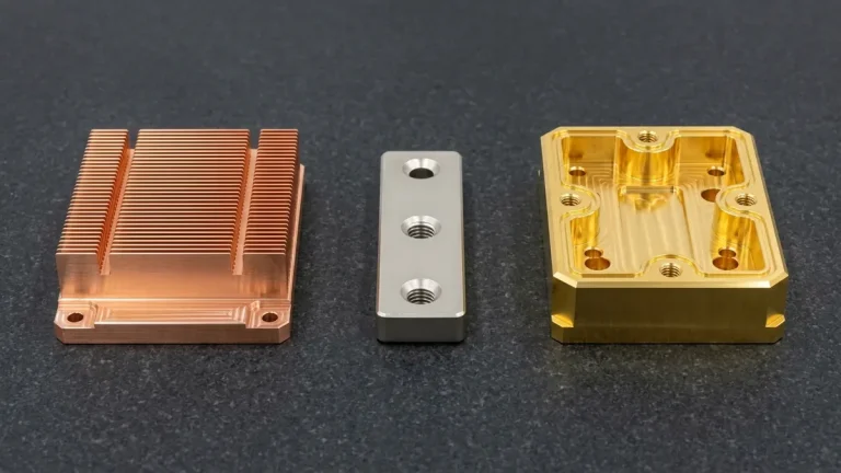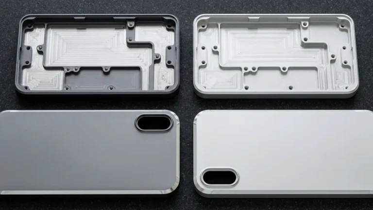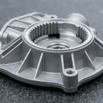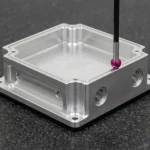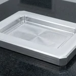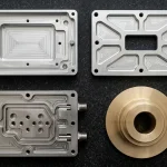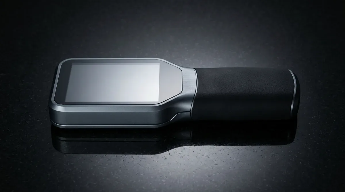
Learning how to achieve the best presentation models is essential for design engineering teams preparing for high-stakes investor pitches, executive product sign-offs, and global trade exhibitions. Unlike rough functional test mules, an exhibition-grade appearance model must convey premium craftsmanship, exact Color, Material, and Finish (CMF) fidelity, and production-identical weight distribution. At our in-house model shop and prototype facility, our master finishing craftsmen combine precision CNC machining with museum-grade custom surface finishes and agile appearance prototyping to transform early industrial designs into stunning physical reality.
- 1. The Anatomy of a Flawless Appearance Model: Beyond Raw 3D Prints
- 2. Step 1: Substrate Selection and Precision CNC Machining
- 3. Step 2: Progressive Surface Preparation and Micro-Filling
- 4. Step 3: Mastering CMF Finishing & Custom Coating Systems
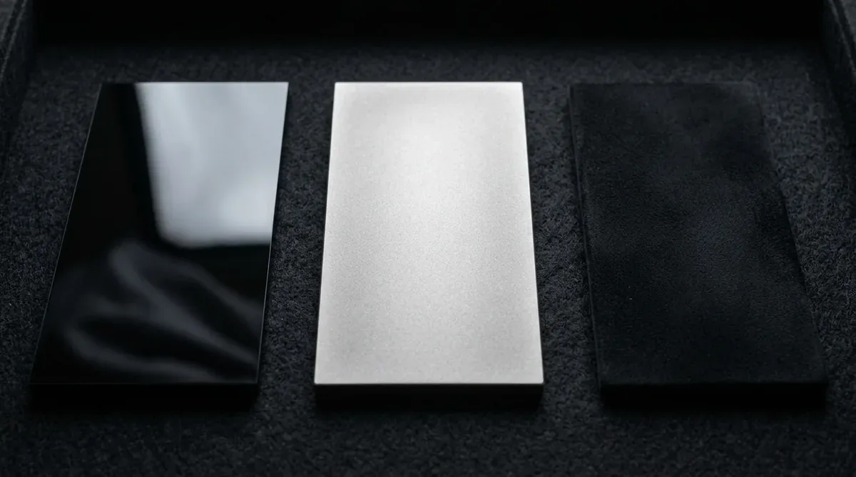
- 5. Presentation Model CMF Specification & Process Matrix
- 6. Step 4: Graphic Detailing, Precision Pad Printing & Laser Etching
- 7. Step 5: Ballast Weighting, Illumination Simulation & Multi-Material Assembly
- 8. Step 6: Metrology, Seam Reveal Inspection & CMF Quality Control
- 9. Technical Engineering FAQ
1. The Anatomy of a Flawless Appearance Model: Beyond Raw 3D Prints
When venture capitalists or corporate stakeholders hold a new product concept, their subconscious reaction is shaped by micro-sensory feedback: the coolness of authentic metal surfaces, the satisfying mechanical dampening of rotary dials, and the complete absence of surface ripples or visible fastener heads. A true presentation model is not merely a painted 3D print; it is a meticulously engineered multi-material assembly that merges high-rigidity metal skeletons, optical-grade transparent windows, and velvety tactile touchpoints.
2. Step 1: Substrate Selection and Precision CNC Machining
Flawless cosmetic finishing begins with an isotropic, dimensionally stable substrate that resists deformation, warping, and solvent swelling:
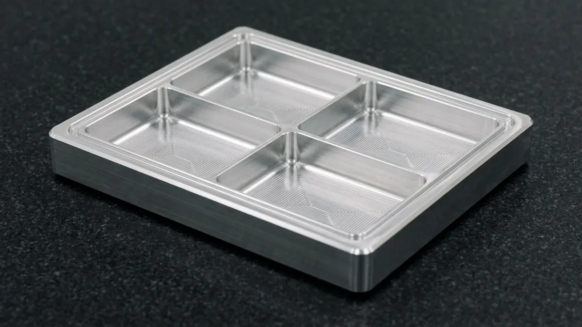
- Aerospace Aluminum (6061-T6 / 7075-T6): Milled with high-speed 3-axis and multi-axis CNC toolpaths using rigid low-profile toe clamping to eliminate thin-wall distortion, achieving maximum efficiency, sharp edge crispness, and genuine metallic weight in handheld devices.
- Dense Engineering Polymers: ABS-FR (flame retardant), semi-crystalline POM (Acetal), and cell-cast PMMA acrylic provide smooth, non-porous surfaces that resist solvent penetration during painting and polishing.
- Parting Line Reveal Channels (Shadow Lines): Rather than striving for an impossible zero-tolerance flush seam that risks uneven step-heights and paint bridging, our machinists incorporate intentional, razor-sharp 0.3 mm x 0.3 mm “reveal” grooves that ensure a consistent, intentional aesthetic boundary across mating parts.
3. Step 2: Progressive Surface Preparation and Micro-Filling
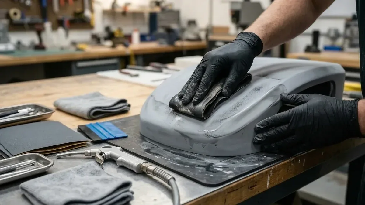
The foundation of any Class-A surface lies beneath the paint layer. Even the slightest micro-chatter from endmills or layer striations from additive masters will telegraph through glossy topcoats if not systematically leveled:
- Epoxy Barrier Priming: High-build polyester or 2K epoxy primers seal micro-tool marks and provide uniform surface tension across multi-material assemblies.
- Dry Guide-Coat Block Sanding: A dark mist coat of dry guide powder is applied across the cured primer. As technicians progress through 400, 600, 1000, and 1500-grit silicon carbide wet papers with ergonomic rubber blocks, the guide coat instantly exposes micro-hollows and orange peel until the surface is optically flat.
- Surface Tension Neutralization: Parts are de-ionized with anti-static air guns and ultrasonically degreased in dust-controlled positive-pressure prep rooms to eliminate static dust attraction prior to spray booth entry.
4. Step 3: Mastering CMF Finishing & Custom Coating Systems
Achieving exact brand aesthetics requires specialized formulation techniques and rigorous optical calibration in controlled environments:
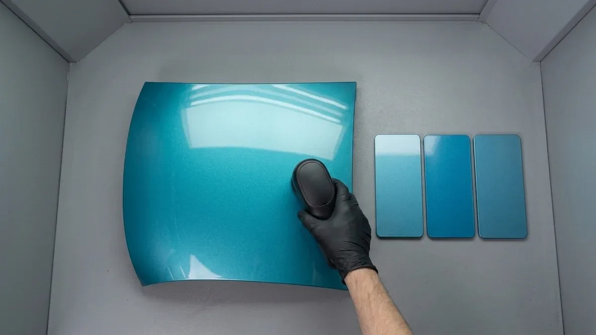
- Spectrophotometer Color Matching: Using computerized spectrophotometers, our paint specialists match custom Pantone, RAL, or customer color swatches within Delta E < 0.5 under calibrated D65 daylight, cool white fluorescent (TL84), and incandescent (Illuminant A) lighting conditions.
- Two-Component (2K) Catalyzed Polyurethane Topcoats: Automotive-grade catalyzed PU coatings provide superior chemical resistance, UV stability, and scratch resistance compared to standard single-part spray enamels.
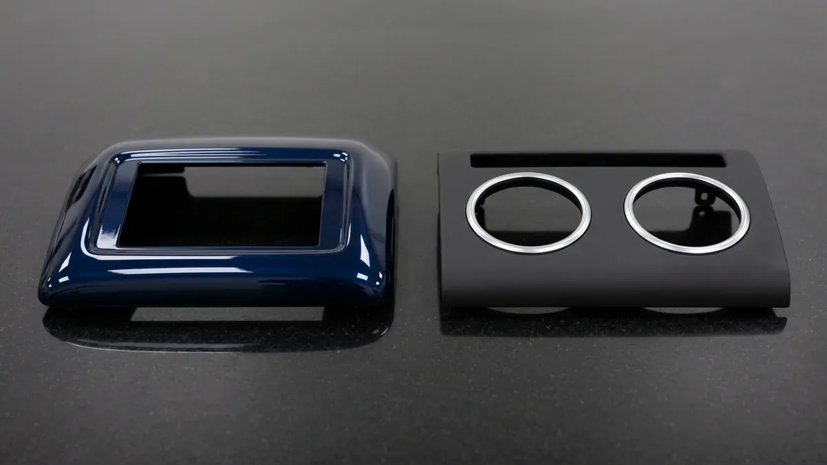
- Tactile Soft-Touch Coatings: Velvety polyurethane elastomer coatings deliver a warm, non-slip, rubberized tactile grip for handheld medical devices and consumer electronics.
- Piano-Black High Gloss: Polished with rotary foam pads, diamond pastes, and micro-fine aluminum oxide compounds to achieve 95+ GU (Gloss Units) with zero swirl marks or distortion.
5. Presentation Model CMF Specification & Process Matrix
The following engineering guide details primary surface finishing techniques, process controls, target gloss ratings, and tactile feedback for presentation models:
| Finish / Texture Style | Substrate Material | Application Process | Target Gloss / Spec | Visual & Tactile Feel |
|---|---|---|---|---|
| Satin Bead-Blast Anodize | 6061-T6 / 7075-T6 Aluminum | #120 Glass bead blast + Type II Anodize | Ra 1.2 μm / Satin Matte | Silky metallic touch; fingerprint resistant |
| Piano-Black High Gloss | Black Cast Acrylic / ABS | Multi-stage cut & buff with diamond paste | > 95 Gloss Units (60°) | Deep mirror reflection; optical depth |
| Soft-Touch Elastomeric | CNC ABS / Polycarbonate | 2K Polyurethane velvet soft coat | Dead Flat (< 5 GU) | Warm, rubberized grip; zero plastic glare |
| Custom Pantone Metallic | ABS / PU Casting Resin | Fine aluminum flake basecoat + 2K clear | Semi-Gloss (30–50 GU) | Automotive metallic flake luster |
| Mirror PVD Metallizing | Polished Brass / ABS | Thermal vacuum evaporation metallizing | > 90% Specular Reflectivity | Brilliant jewelry-grade mirror chrome |
| Optical Clear Polishing | Cell-Cast PMMA Acrylic / PC | SPDT diamond fly-cutting + progressive buff | 92% Transmittance (PMMA) | Crystal-clear clarity without haze |
6. Step 4: Graphic Detailing, Precision Pad Printing & Laser Etching
Presentation models require immaculate graphic registration to simulate production molded markings and regulatory compliance data:
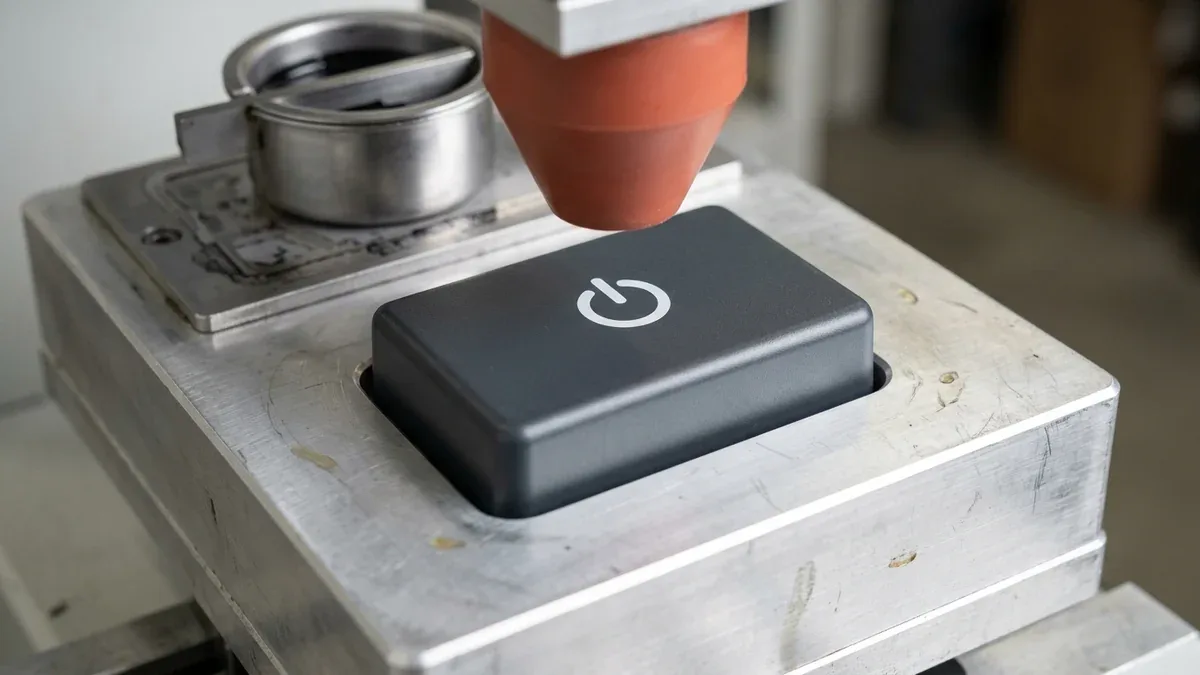
- Micro-Registration Pad Printing: Regulatory icons, compliance logos (CE, FCC), power symbols, and button text are transferred using custom silicone rubber tampons and laser-etched hardened steel cliché plates, achieving sub-0.1 mm alignment accuracy across compound 3D curves.
- Fiber Laser Etching on Anodized Surfaces: For aluminum bezels, high-precision fiber lasers ablate the dye layer of anodized coatings to produce permanent, razor-sharp white or silver vector graphics that cannot peel or wear.
- High-Resolution UV Flatbed Printing: Complex multi-color branding and micro-gradients are applied with industrial UV-cured inkjet printing at up to 1440 DPI, cured instantly with cold LED lamps to prevent thermal distortion of thin plastic walls.
7. Step 5: Ballast Weighting, Illumination Simulation & Multi-Material Assembly
To finalize the presentation model for executive demonstration and ergonomic evaluation:
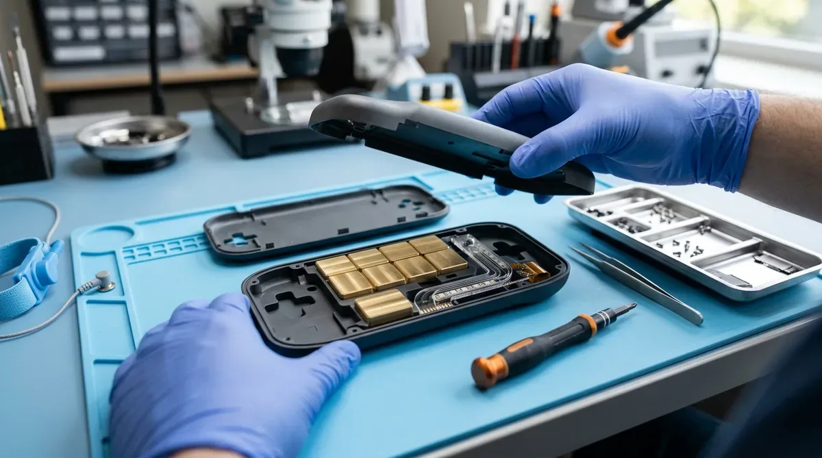
- Internal Ballast Counterweighting: Empty polymer prototype shells feel unconvincingly light. Our machinists create custom CNC-machined brass or steel ballast blocks concealed internally to accurately match the exact production mass and center of gravity of internal batteries, motors, and PCB stacks.
- Active Illumination Simulation: Dummy display bezels incorporate diamond-polished acrylic light pipes backlit by micro SMD LEDs and diffusion films, simulating active OLED screens or indicator halos without software development overhead.
- Concealed Magnetic Fasteners: Rather than relying on exposed screws or brittle temporary snap-fits, exhibition models utilize concealed miniature neodymium magnets and alignment dowels to ensure repeatable, seamless disassembly during design reviews.
8. Step 6: Metrology, Seam Reveal Inspection & CMF Quality Control
Before leaving our workshop, presentation models undergo thorough metrology verification to guarantee showroom perfection:
- 60-Degree Micro-Glossmeter Verification: Every painted, buffed, or textured surface is verified against CMF master coupons (e.g., verifying piano-black finishes exceed 95 GU and soft-touch coats remain below 5 GU).
- Non-Contact 2.5D Optical Inspection (VMS): Multi-part assemblies are placed on vibration-isolated granite tables where high-magnification optical comparators measure reveal groove consistency (0.3 mm ± 0.03 mm) and flushness across parting lines.
- Coating Adhesion & Hardness Testing: Test coupons processed alongside prototypes undergo ASTM D3363 pencil hardness testing (minimum 2H rating) and cross-hatch tape adhesion testing (ASTM D3359 Class 4B/5B) to ensure finishes withstand extensive handling during exhibitions.
9. Technical Engineering FAQ
Our paint formulation laboratory utilizes computerized spectrophotometers and high-precision micro-gram analytical scales to blend automotive-grade 2K polyurethane pigments. Test coupons are baked and evaluated inside calibrated D65 daylight viewing booths to guarantee a color difference of Delta E < 0.5 under multiple lighting standards.
Empty plastic prototype shells feel hollow and unconvincing in executive and investor hands. Machining concealed brass or steel ballast blocks to replicate the exact mass, heft, and center of gravity of production batteries, motors, and PCB assemblies delivers immediate tactile credibility.
A fully finished, multi-material exhibition presentation model—incorporating high-efficiency 3-axis CNC milling, progressive primer preparation, custom CMF painting, graphics pad printing, and weighted assembly—typically requires 7 to 12 business days of factory production and inspection turnaround.
Specify Verified Surface Finishes on Custom Precision Components
Ensure dimensional allowance control, thread masking accuracy, and MIL-A-8625 or ASTM surface compliance from raw billet machining through final finishing. Upload your 3D CAD models and 2D prints for a complete engineering DFM review.
Upload CAD & Drawings for Finishing DFM Review