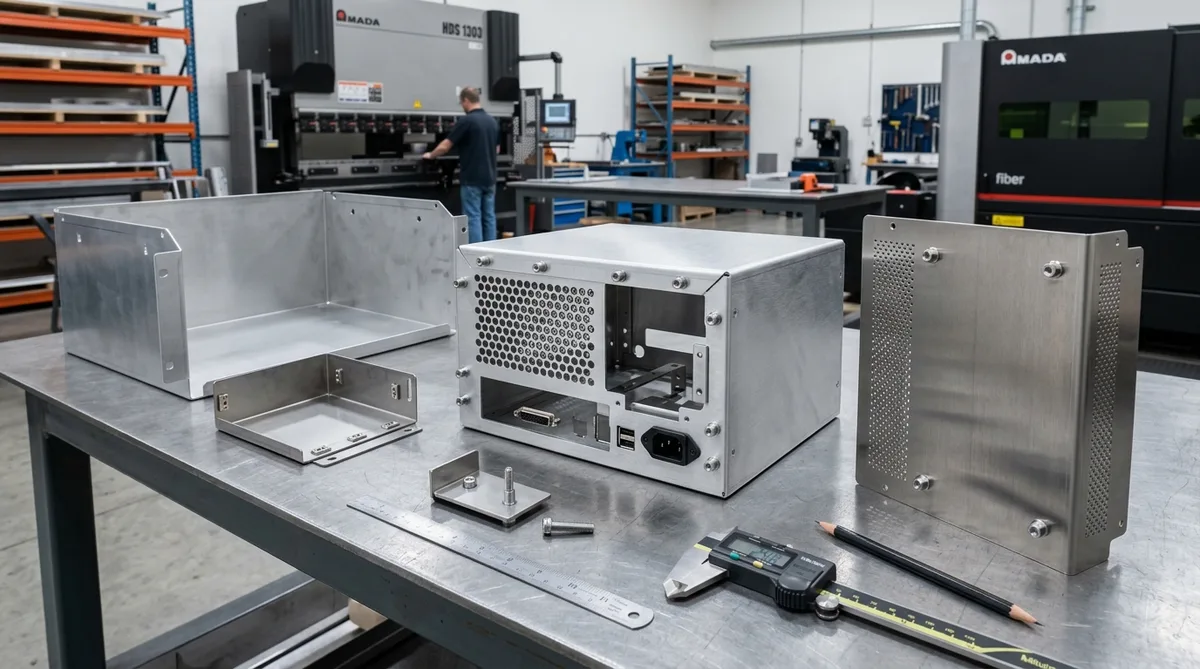
Accelerating hardware development hinges on rapid, accurate sheet metal prototyping to validate structural integrity, thermal airflow, and electromagnetic shielding before committing to mass stamping tooling. From server rack chassis and robotics enclosures to medical consoles, fabricated sheet metal components deliver high strength-to-weight ratios without the steep financial investment and long lead times of hard stamping dies. At our in-house facility, our sheet metal fabrication division integrates multi-kilowatt fiber laser cutting, precision CNC press brakes, and seamless hardware insertion to deliver production-grade custom sheet metal prototyping services with turns as fast as 3 to 5 business days.
Design for Manufacturability (DFM): The 4 Pillars of Sheet Metal
Transforming a 3D CAD sheet metal model into a reality requires understanding how metals deform plastically under compressive and tensile forces during bending:
- K-Factor and Bend Allowance: The neutral axis of a sheet shifts inward during bending. Utilizing exact K-factors (typically 0.38 to 0.45 for air bending aluminum and cold-rolled steel) ensures flat blank cut lengths fold into the exact outer dimensions modeled in CAD.
- Minimum Internal Bend Radius (IR): To prevent outer-fiber tearing and micro-cracking, internal bend radii should generally equal or exceed material sheet thickness (IR ≥ 1.0T for 5052-H32 aluminum and 304 stainless steel).
- Hole and Slot Edge Relief: Cutouts positioned too close to a bend line will deform oval. Maintain a minimum clearance of Distance ≥ 2.5T + Bend Radius from any hole edge to the tangent bend line.
- Corner Bend Reliefs: Where two bends intersect at a corner, tear reliefs (such as circular or rectangular cutouts extending past the bend zone) must be incorporated to prevent unwanted bunching and localized material fracture.
Fabrication Workflow: Laser Cutting to Hardware Clinching
Precision prototype fabrication follows a tight sequence of CNC automated steps:
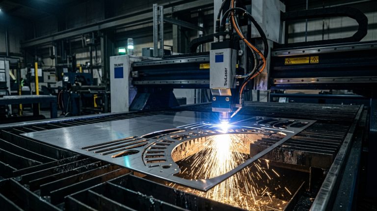
- CNC Fiber Laser Blanking: 6 kW fiber laser cutters slice complex perimeter profiles, venting perforation grids, and mounting slots with ±0.05 mm accuracy while maintaining narrow heat-affected zones (HAZ).
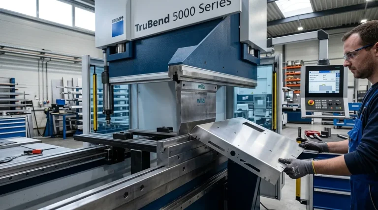
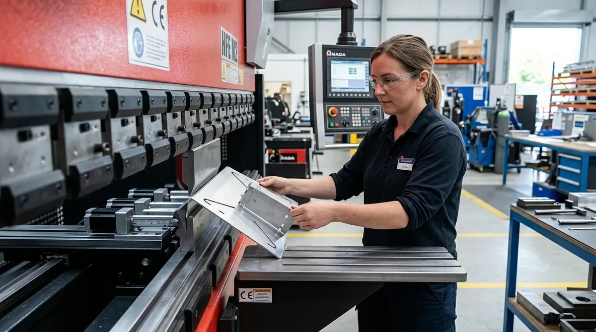
- Multi-Axis CNC Air Bending: Programmable CNC press brakes utilizing segmented precision-ground tooling execute progressive bends, with optical laser angle-measuring systems correcting for material springback in real time.
- Self-Clinching PEM Fastener Insertion: Hydraulic presses install flush-head studs, blind standoffs, and threaded nuts into laser-cut holes, providing permanent, high-torque threads without thermal distortion from welding.
- TIG / Fiber Laser Welding: For hermetically sealed or high-strength assemblies, robotic fiber laser welding delivers minimal thermal warpage, followed by automated robotic grinding to create smooth, seamless outer corners.
Sheet Metal Alloy Selection & Minimum Bend Radii Guide
Choosing the proper alloy balance between formability, strength, and environmental resistance is critical:
| Alloy Grade | Temper / State | Min. Bend Radius (IR) | Typical Applications | Recommended Finish |
|---|---|---|---|---|
| Aluminum 5052 | H32 | 1.0 × T | Electronic chassis, brackets, marine panels | SurTec 650 / Powder Coat / Anodize |
| Stainless Steel 304 | 2B Annealed | 1.0 × T | Medical enclosures, food processing, harsh environments | Passivation / #4 Brushed / Bead Blast |
| Cold Rolled Steel | SPCC / 1018 | 0.8 × T | High-load structural brackets, server racks | Zinc Plating (Cr3+) / Powder Coating |
| Galvanized Steel | SGCC / G90 | 1.0 × T | HVAC ducts, outdoor utility junction boxes | Mill Galvanized / Bare Passivated |
| Copper / Brass | C11000 / C26000 | 0.5 × T | Electrical busbars, RF shields, heat sinks | Tin Plating / Bright Nickel Plating |
Precision Sheet Metal Tolerancing Guidelines
Achieving repeatable fits across mating sheet metal panels requires standard tolerance agreements:
| Dimension Classification | Standard Tolerance | Precision Tolerance | Inspection Method |
|---|---|---|---|
| Laser Cut Hole Diameter | ±0.100 mm | ±0.050 mm | Pin gauges / Optical vision system |
| Hole-to-Hole Center Distance | ±0.120 mm | ±0.075 mm | Digital calipers / Zeiss CMM |
| Formed Flange Length | ±0.250 mm | ±0.125 mm | Height gauge on granite surface plate |
| Bend Angle Accuracy | ±1.0° | ±0.5° | Digital universal bevel protractor |
| Overall Enclosure Squareness | ±0.500 mm | ±0.250 mm | Diagonal measurement verification |
Frequently Asked Questions
Why is aluminum 5052 preferred over 6061 for sheet metal bending?
Aluminum 5052-H32 contains magnesium as its primary alloying element, granting exceptional ductility that allows tight 90-degree bends without cracking at a 1T bend radius. Conversely, 6061-T6 is significantly more brittle and prone to fracture unless formed with a much larger bend radius (often 2.5T to 3T) or in an annealed O-temper state.
What is the purpose of corner bend reliefs in sheet metal design?
When two bends meet at a 90-degree corner, the intersecting metal compresses and tears without dedicated reliefs. Incorporating rectangular or circular corner bend reliefs cut past the bend lines relieves localized hydraulic plastic stress, preventing torn edges and ensuring clean mating seams.
Can threaded holes be tapped directly into thin sheet metal?
Tapping directly into sheet metal thinner than 2.0 mm rarely provides enough thread engagement (minimum 3 full threads) to withstand tightening torque. The standard engineering solution is installing self-clinching PEM fasteners (nuts, studs, or standoffs) via hydraulic press or utilizing sheet extrusion (flow drilling) to create an elongated tapped collar.
Launch Your Custom Sheet Metal Prototypes Fast
From laser-cut chassis panels and complex multi-bend brackets to fully welded enclosures with PEM hardware, our in-house facility delivers fast turnarounds and precision tolerances. Upload your 3D CAD models (STEP / IGES) and 2D drawings today for an instant DFM evaluation and quote.
Upload CAD Files for Sheet Metal Fabrication →