The manufacturing sector thrives on precision, understanding that the smallest dimensional differences can have major consequences for product quality, cost, and usability. A prime example is press fitting, where achieving the correct interference, often controlled down to the micrometer, is vital to prevent component failure. To clarify this crucial process, this article will cover: the definition of a press fit, the key factors influencing its tolerancing, a practical calculation example, and important tips for designing components intended for press fitting.
What is a Press Fit?
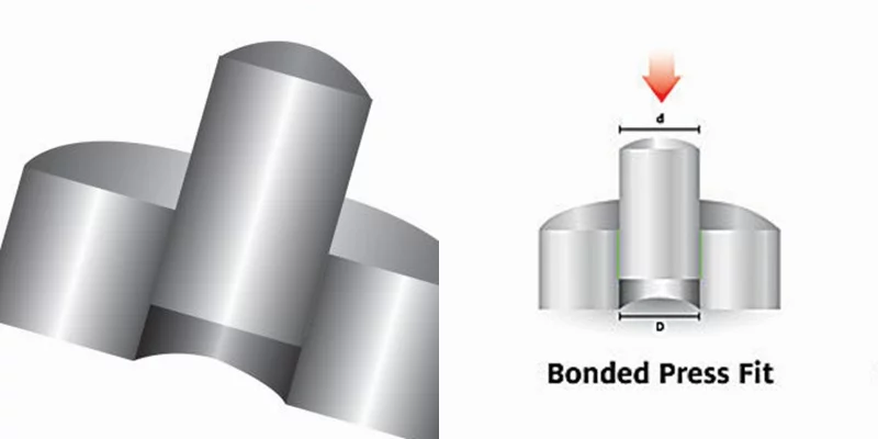
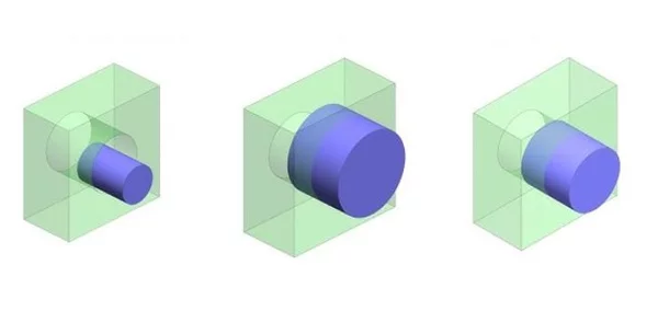
Let’s start by defining a press fit, also commonly referred to as an interference fit. It’s a type of mechanical fastening created when two components are forced together. The fundamental characteristic of a press fit is designed interference: one component (like a shaft) is intentionally manufactured slightly larger than its mating component (like a hole). Once assembled, this size difference generates significant frictional forces at the mating surfaces, holding the parts firmly in place.
Understanding Press Fit Tolerance
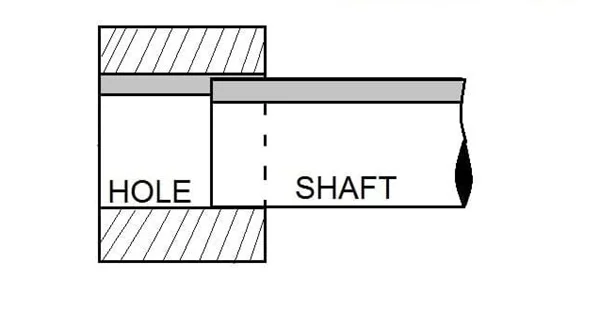
Press fit tolerance governs the acceptable range for this size difference, ensuring that interference is always present between the mating parts within their specified manufacturing limits. This guarantees that the smallest permissible shaft dimension is still larger than the largest permissible hole dimension (or conversely, the largest hole is smaller than the smallest shaft). As a result, external force is always necessary to assemble the components; they cannot simply slide together.
This mandatory interference is what distinguishes press fits from other engineering fits. Clearance (or slip) fits, for instance, are designed with a guaranteed gap between parts for easy assembly and potential movement. Transition fits fall in between, potentially resulting in either a slight interference or a small clearance, depending on the actual dimensions of the specific parts being assembled.
Shaft and Hole Basis Systems
Press fit tolerances are defined using one of two standard systems: the Hole Basis System or the Shaft Basis System. The choice depends on which component dimension is considered fixed or standard in the design.
- Hole Basis System: This is used when the hole dimension is fixed (often due to using standard components like bearings or bushings). The tolerance is then applied to the shaft, specifying the acceptable range of shaft diameters needed to achieve the desired interference with the standard hole. For example, since a standard bearing’s inner ring diameter (the hole) is fixed, the hole basis system dictates the required tolerance for the mating shaft.
- Shaft Basis System: Conversely, this system is employed when the shaft diameter is the fixed dimension. The tolerance is applied to the hole, defining the range of acceptable hole sizes to create the necessary interference with the standard shaft. For instance, when mounting a bearing’s outer ring (the shaft in this context, relative to the housing) into a custom-designed machine housing, the shaft basis system might be used, applying the tolerance to the housing’s bore (the hole).
Key Factors Influencing Press Fits
Achieving a reliable press fit requires careful consideration of several interconnected factors:
- Material Properties: The characteristics of both mating parts—particularly their hardness, elasticity (Young’s Modulus), and coefficient of thermal expansion—are crucial. Significant differences, especially in hardness, can cause the softer material to deform excessively during assembly or under load, altering the intended interference and potentially leading to joint failure. Ideally, materials with similar relevant properties are preferred for durability.
- Interference Amount: This is arguably the most critical factor. The magnitude of the interference dictates the holding force and induced stresses.
- Too much interference: Generates excessive stress within the components, potentially causing yielding, cracking, or fracture during assembly or in service.
- Too little interference: Results in insufficient frictional force to hold the components securely, leading to slippage, fretting, or complete disassembly under operating loads or vibrations.
- Surface Roughness: The texture of the mating surfaces directly impacts friction and the actual contact area.
- Smoother surfaces: Generally provide a larger effective contact area, leading to more uniform stress distribution and potentially higher static friction once assembled.
- Rougher surfaces: The peaks (asperities) can initially increase resistance to slippage and improve damping. However, rough surfaces have less actual contact area, can trap air or contaminants, and the peaks may flatten over time (loss of interference). The optimal surface roughness is a design choice, balancing holding power, stress concentration, and assembly requirements.
- Temperature: Materials expand when heated and contract when cooled. This must be considered both for operating conditions and assembly.
- Operating Temperature: Significant temperature changes during operation can alter the dimensions enough to increase or decrease the interference, potentially compromising the joint.
- Assembly Temperature: Often, one component is heated (expanding the hole) or cooled (shrinking the shaft) to temporarily reduce the interference, making assembly easier. This requires careful control to avoid overheating or overcooling, which could permanently alter the material’s properties (e.g., temper or hardness).
- Manufacturing Tolerance: Since the target interference range for press fits is often measured in micrometers (µm), precise manufacturing is essential. The design must specify achievable manufacturing tolerances for both the shaft and the hole to ensure the actual interference on assembled parts consistently falls within the calculated acceptable range. Deviations outside the tolerance zone lead directly to the problems of too much or too little interference.
- Assembly Method: The technique used to force the parts together impacts the joint’s quality.
- Alignment: Careful initial alignment is critical to prevent gouging, uneven stress distribution, and potential component damage.
- Force Application: While simple hammering might suffice for non-critical applications, controlled force application using tools like hydraulic or arbor presses is preferred for precision fits to ensure even pressure and prevent damage.
- Temperature Assistance: As mentioned, using temperature differences is effective but must be managed carefully to avoid material degradation.
Using a Press Fit Tolerance Chart
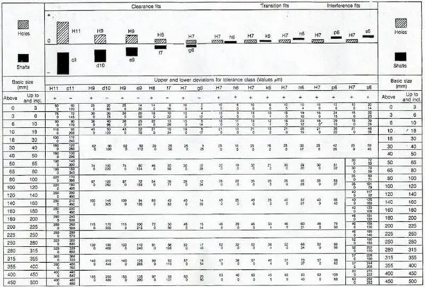
One of the most common and efficient methods for selecting appropriate engineering tolerances for press fits is by referencing standardized tolerance charts. These charts condense complex tolerance system data (like ISO or ANSI standards) into a convenient and comprehensible format. They provide pre-calculated tolerance zones for various nominal sizes and fit types, significantly simplifying and accelerating the process of determining the correct dimensions for mating parts.
Given that complete tolerance charts contain extensive information, often spanning multiple pages to cover a wide range of sizes and fit classifications, we will present a representative sample below. This example illustrates the typical layout and the kind of information these charts provide.
Using a Tolerance Chart: Typical Workflow
Tolerance charts provide a standardized way to select press fit parameters. The typical process involves these steps:
- Determine the Basis System: Decide whether to use the Hole Basis or Shaft Basis system, depending on which component (hole or shaft) has the fixed or standard dimension in your design.
- Select the Fit Type: Choose the appropriate class of interference fit based on the application’s requirements – common categories include:
- Locational Interference Fits (e.g., LN): Lightest interference, primarily for location accuracy, requiring minimal force.
- Drive Fits (e.g., FN1-FN2): Medium interference, requiring moderate assembly force, suitable for transmitting light loads or torque.
- Force Fits (e.g., FN3-FN5): Heaviest interference, requiring significant assembly force (often with thermal assistance), designed for transmitting high loads or torque and ensuring a permanent assembly.
- Identify Nominal Size: Locate the row or section in the chart corresponding to the nominal diameter of your shaft or hole.
- Extract Tolerance Limits: Note the specified upper and lower tolerance limits for both the shaft and the hole for the chosen fit type and nominal size. These define the acceptable range of manufactured dimensions.
- Specify on Drawings: Clearly indicate these tolerance limits on the engineering drawings for both mating components.
Techniques to Achieve and Control Press Fit Tolerances
While designing the correct tolerance is crucial, consistently manufacturing parts within the tight micrometer-level specifications required for press fits presents the main challenge. Production experts employ several high-precision techniques:
- CNC Machining: Computer Numerical Control (CNC) machining processes (like turning and milling) are fundamental for achieving the precise initial dimensions required. Achieving the final tolerance often relies heavily on carefully controlled finishing passes. These typically use high cutting speeds, shallow depths of cut, and appropriate tooling and coolant to minimize cutting forces, vibration, and heat generation, resulting in accurate dimensions and the desired surface finish on the mating surfaces.
- Precision Grinding: Grinding is often used as a secondary or finishing operation after initial CNC machining. It excels at achieving extremely tight dimensional tolerances (sub-micrometer accuracy is possible) and specific surface roughness requirements critical for press fit performance.
- Measurement and Quality Control: Rigorous inspection is non-negotiable. Quality control departments use sophisticated measurement tools, such as Coordinate Measuring Machines (CMMs), profilometers, and precision gauges, to verify that the manufactured components meet the specified dimensional and geometric tolerances (like roundness and cylindricity). This step is essential not only for accepting or rejecting parts but also for providing crucial feedback to the manufacturing team to identify and correct process deviations. In some instances, slightly out-of-tolerance parts might be identified as suitable for rework rather than being scrapped.
Industrial Best Practices for Reliable Press Fits
Beyond the technical specifications, experienced professionals emphasize practical considerations to ensure successful and durable press fits:
- Material Compatibility: As highlighted earlier, ensuring compatible material properties is vital. Select materials with reasonably similar hardness and toughness to prevent excessive deformation or damage to the softer component during assembly. Critically, consider the coefficients of thermal expansion, especially if the assembly will operate over a wide temperature range. A significant mismatch can cause the interference to increase or decrease undesirably at operating temperatures, potentially leading to failure.
- Edge Preparation (Lead-in): Since press fitting involves forcing components together, sharp edges on the mating parts can cause scoring, galling, misalignment, or high stress concentrations during initial engagement. To facilitate smooth assembly and prevent damage, incorporate lead-in features on the inserting part (usually the shaft). Common methods include adding a small chamfer or a slight radius to the leading edge. This helps guide the part into the hole and allows the interference fit to establish gradually.
Lubrication During Assembly
Applying a suitable lubricant to the mating surfaces prior to assembly can significantly ease the press fitting process. Lubrication reduces the friction between the components, which in turn lowers the required assembly force and minimizes the risk of surface damage like scoring or galling, especially with tighter fits or larger contact areas.
However, lubrication is not always necessary or desirable. The choice of lubricant (type and viscosity) and the amount applied must be carefully considered. Excessive or inappropriate lubrication can potentially reduce the final holding force of the joint or introduce contaminants. The decision to use lubrication depends on the specific materials, interference amount, surface finish, and assembly method.
Using Adhesives (Retaining Compounds)
In certain applications, adhesives, more specifically anaerobic retaining compounds, are applied to the mating surfaces before assembly. This is typically done not just to ease assembly (though some compounds have lubricating properties initially), but to augment the mechanical press fit.
Using a retaining compound can:
- Increase Joint Strength: Significantly enhances the torque transmission capability or axial holding force beyond what friction alone provides.
- Fill Microscopic Gaps: Seals the joint against leakage and corrosion by filling the small voids between the mating surfaces.
- Improve Reliability: Allows for slightly relaxed machining tolerances in some cases, as the adhesive compensates for minor variations.
- Enhance Damping: Can improve the joint’s resistance to vibration and fretting.
Common Applications of Press Fits
Press fit assemblies are utilized across a vast spectrum of engineering fields due to their strength and reliability. Some common examples include:
- Automotive: Securing piston pins in connecting rods, attaching crankshaft counterweights, mounting bearings.
- Aerospace: Assembling turbine shafts with bearings, critical structural joints.
- Hydraulics & Pneumatics: Creating robust, leak-free connections for pipes, valves, and fittings.
- Robotics: Mounting gears and bearings onto shafts within robotic joints and actuators.
- Industrial Machinery: Installing bearings in housings, assembling spindle shafts, connecting couplings.
Conclusion
Press fit tolerancing is a fundamental engineering principle essential for creating strong, reliable mechanical joints in countless applications. Successfully designing and implementing press fits demands a thorough understanding of the underlying concepts, careful consideration of material properties and operating conditions, and precise calculation and manufacturing control.
AS Prototypes: Your Partner for Precision Press Fit Components
At AS Prototypes, we specialize in high-precision CNC machining services, expertly handling applications that demand tight tolerances, including those required for reliable press fits. Leveraging advanced machining capabilities like CNC milling and turning, alongside rigorous quality control processes, we ensure your components meet the strictest dimensional accuracy and surface finish requirements.
From automotive and aerospace to robotics and industrial machinery, we provide dependable, precision-machined parts. Partner with AS Prototypes for expert manufacturing solutions tailored to your specific press fit and engineering needs. Contact us to discuss your project at info@asprototypes.com.
FAQs
- What is the difference between a press fit and a transition fit? A press fit always has guaranteed interference between the mating parts within their tolerance zones, resulting in a tight, force-assembled joint. A transition fit occupies the tolerance range between a clearance fit and an interference fit; depending on the actual manufactured sizes of the specific mating parts, it could result in either a small clearance or a slight interference.
- What are common standards for press fit tolerances? Widely recognized standards governing press fit tolerances include ISO 286 (International), ANSI B4.1 (American), and DIN 7157 (German). These systems provide standardized codes for different fit types and tolerance grades.
- How is a reliable press fit achieved? Achieving a reliable press fit involves several key factors: accurately calculating tolerances using established standards (like ISO or ANSI) based on application requirements, selecting compatible materials (considering hardness, elasticity, and thermal expansion), employing high-precision manufacturing techniques (like CNC machining and grinding) to meet tight dimensional specifications, and controlling the assembly process carefully.