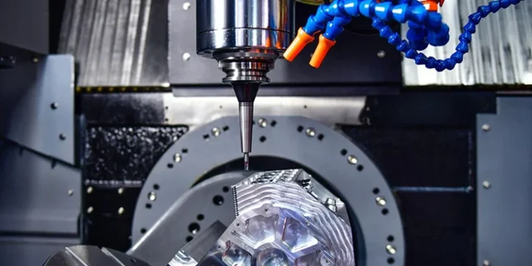
Deep cavity parts, especially those with narrow internal geometries, are among the most challenging tasks in CNC milling. Common technical issues include excessive tool overhang, poor chip evacuation, and inadequate cooling. If left unoptimized, these problems drastically reduce tool life, degrade surface quality, and lower production efficiency.
In this guide, we will break down the key considerations for machining deep, narrow cavities and share an actionable process optimization strategy used by AS Prototypes to achieve high-precision results efficiently.
Key Considerations for CNC Machining of Deep and Narrow Cavities
When engineering and machining deep, narrow cavities, maintaining dimensional accuracy depends on managing five critical technical factors:
- Tool Deformation Control: Longer cutting tools are inherently prone to deflection and bending under cutting forces. This deflection directly impacts dimensional tolerances and compromises surface integrity.
- Efficient Chip Evacuation: In deep pockets, aluminum or steel chips tend to accumulate at the bottom. Without immediate removal, recutting chips leads to rapid tool wear or catastrophic tool breakage.
- Vibration Mitigation (Chatter): High depth-to-width ratios often require extended tool overhangs. Without proper stability countermeasures, severe vibration will degrade both surface finish and spindle health.
- Optimal Depth-to-Width Ratio: For standard setups, maintaining a cavity depth-to-width ratio between 3:1 and 4:1 helps ensure stable machining dynamics.
- Depth-to-Fillet Radius Ratio: When the ratio of cavity depth to the corner fillet radius reaches or exceeds 10:1, it is classified as an ultra-deep cavity. A larger ratio necessitates longer, thinner tools, drastically elevating the machining difficulty.
Case Study: Aluminum Deep Cavity Machining
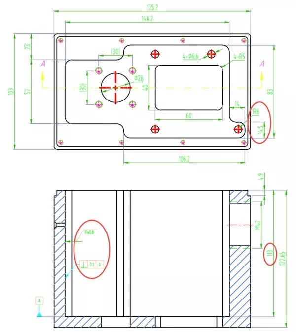
To illustrate practical manufacturing solutions, AS Prototypes recently optimized a real-world aluminum cavity project. The component featured an ultra-deep, narrow configuration with a depth of 113 mm, a minimum width of 14.5 mm, and a tight internal corner fillet radius of 6 mm.
Technical Part Overview
- Material: AL7075-T6 (High-strength aircraft aluminum)
- Overall Dimensions: 175.2 × 103 × 122.65 mm
- Cavity Profile: Maximum internal dimensions of 146.2 × 83 mm, narrowing down to a critical section of 14.5 × 14 mm. With a depth of 113 mm and a 6 mm corner radius, the depth-to-radius ratio reaches 19:1, placing it in the ultra-deep machining category.
Core Manufacturing Challenges
- Rigidity Deficit: A standard Diameter 12 mm cutting tool requires over 115 mm of overhang, meaning the tool depth exceeds 5 times its diameter, resulting in a critical loss of tool rigidity.
- Chip Packing: High-speed milling of AL7075-T6 generates a massive volume of ductile chips. These accumulate faster than standard coolant can remove them, risking tool wrapping.
- Strict Surface Specifications: The internal walls required a strict surface roughness finish of Ra <= 0.8 um.
- Geometry Tolerances: The perpendicularity of the deep internal walls had a demanding tolerance of <= 0.1 mm.
How to Optimize Process Strategies?
To maximize roughing efficiency and stabilize tool performance during the bulk material removal phase, AS Prototypes implemented a three-pronged manufacturing strategy:
1. Pre-Drilled Tool Entry Strategy
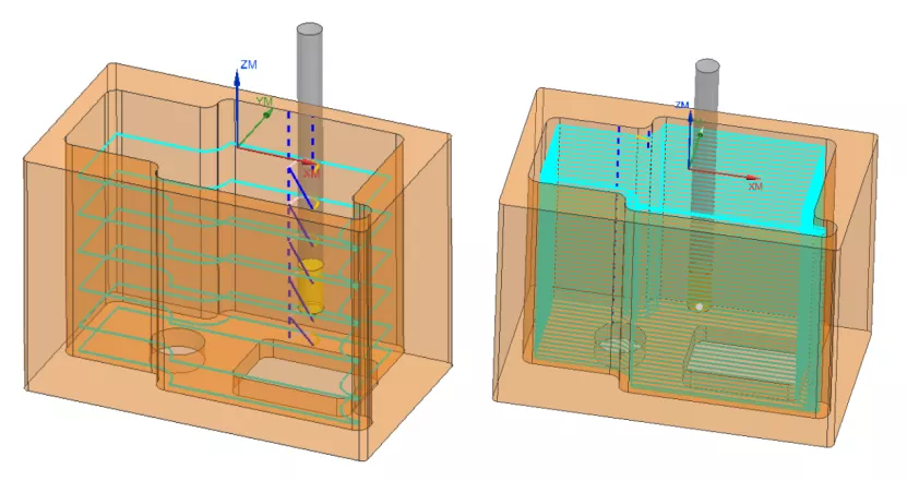
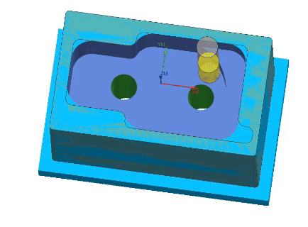
Plunging a milling cutter directly into stock material along the Z-axis creates severe impact forces and poor initial chip clearance. To mitigate this, we pre-drilled two Diameter 22 mm through-holes at the bottom of the cavity.
These pilot holes served a dual purpose: they acted as low-load vertical entry channels for the roughing tools and provided an immediate escape route for chips to fall through, completely bypassing vertical plunging stress.
2. Stage-Based Segmented Rough Machining
Instead of using a single tool for the entire depth, material removal was divided into three distinct stages to match tool rigidity with depth:
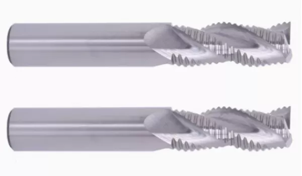
- Stage 1: High-Efficiency Dynamic Roughing (0–65 mm)We utilized an Diameter 18 mm solid carbide 3-flute wavy end mill (70 mm projection). Employing adaptive dynamic milling paths (S4000 / F1800, 25 mm axial depth, 1.8 mm radial width) maximized initial metal removal rates.
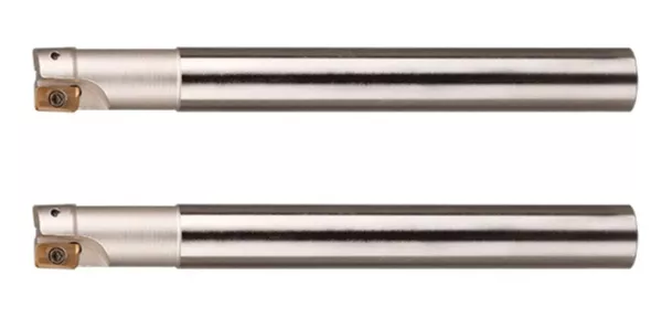
- Stage 2: Stable Deep Roughing with Insert Cutters (65–113 mm)To handle the remaining depth safely, an anti-vibration extended Diameter 20 mm indexable insert cutter (130 mm overhang) was deployed. Stepwise roughing parameters (S2800 / F2000, 0.5 mm depth of cut, 14 mm width of cut) guaranteed safe, chatter-free roughing to the floor.
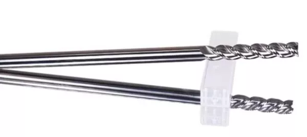
- Stage 3: Corner Rest-Milling for Uniform Finishing AllowanceA secondary roughing cycle used an extended Diameter 12 mm solid tungsten carbide end mill (125 mm overhang) at S3000 / F1500. This cleared the large corner radii left by previous tools, ensuring a completely uniform 0.2 mm finishing allowance across all internal walls.
3. Advanced Tool Material and Geometry Selection
Tool substrate selection is paramount when tackling sticky aluminum alloys at depth. In our testing, YW-type carbide inserts demonstrated significantly better heat dissipation and anti-adhesion (built-up edge resistance) properties compared to traditional YG and YT-type options, effectively preventing thermal degradation at the cutting edge.
Optimizing Finishing Tool Paths
Achieving an Ra <= 0.8 um surface finish and 0.1 mm perpendicularity requires careful selection of the finishing tool path.
| Tool Path Strategy | Execution Profile | Pros & Cons |
| Layer-by-Layer Finishing | The tool steps down incrementally along the Z-axis, executing auxiliary entries/exits at each layer. | Pros: High programmatic efficiency. Cons: Leaves visible entry/exit witness marks. Tool deflection varies by depth, causing an undesirable wall taper. |
| Optimized One-Pass Spiral | The tool path employs a continuous, unbroken downward spiral with a single entry and exit point. | Pros: Eliminates step-down marks. Maintains a constant, uniform cutting load and speed, ensuring perfect wall perpendicularity (<= 0.1 mm). |
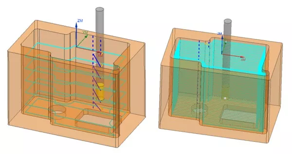
By opting for the Optimized One-Pass Spiral Machining technique, AS Prototypes neutralized the variable forces caused by tool deflection, delivering a pristine, seamless finish from the top of the cavity to the very bottom.
Dual-Channel High-Pressure Coolant System
Even with optimal tool paths and pre-drilled chip clearance holes, high-speed aluminum milling generates chip volumes that can rapidly choke a narrow pocket.
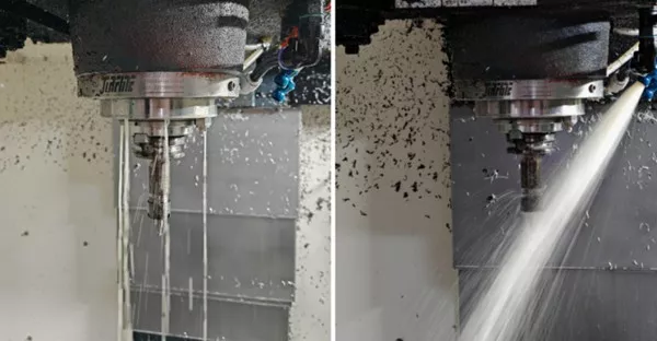
To counteract this, we integrated a dual-channel high-pressure coolant system utilizing simultaneous vertical and lateral fluid outlets. This setup guaranteed that high-pressure coolant continuously targeted the cutting zone, instantaneously flushing chips away from the tool edges and mitigating thermal spikes.
Final Results and Summary
By pairing high-performance CNC equipment with intelligent process optimization, AS Prototypes delivered exceptional manufacturing metrics on this challenging project:
- 42% Reduction in rated cycle time per workpiece.
- 125% Increase in overall tool service life.
- Flawless Surface Quality: Consistently achieved Ra <= 0.8 um.
- Geometric Precision: Maintained strict verticality and perpendicularity <= 0.1 mm.
Key Takeaways for Engineers
- Path Strategy Over Raw Speed: Intelligent tool path generation (like spiral finishing) is just as vital as buying high-end tooling.
- Segmented Depth Control: Breaking roughing into depth stages dramatically mitigates the harmonics and vibration associated with long tool overhangs.
- Chip Control is Mandatory: High-pressure, multi-directional delivery is the baseline requirement for deep pocket aluminum milling.
High-tolerance deep cavity machining doesn’t always demand exotic, ultra-expensive machinery. Through rigorous process sequencing, optimized tool geometries, and tight environmental controls, elite quality is fully achievable on standard setups.
Need expert engineering support to optimize your next complex deep cavity or tight-tolerance manufacturing project? Contact AS Prototypes today to consult with our project engineering team.