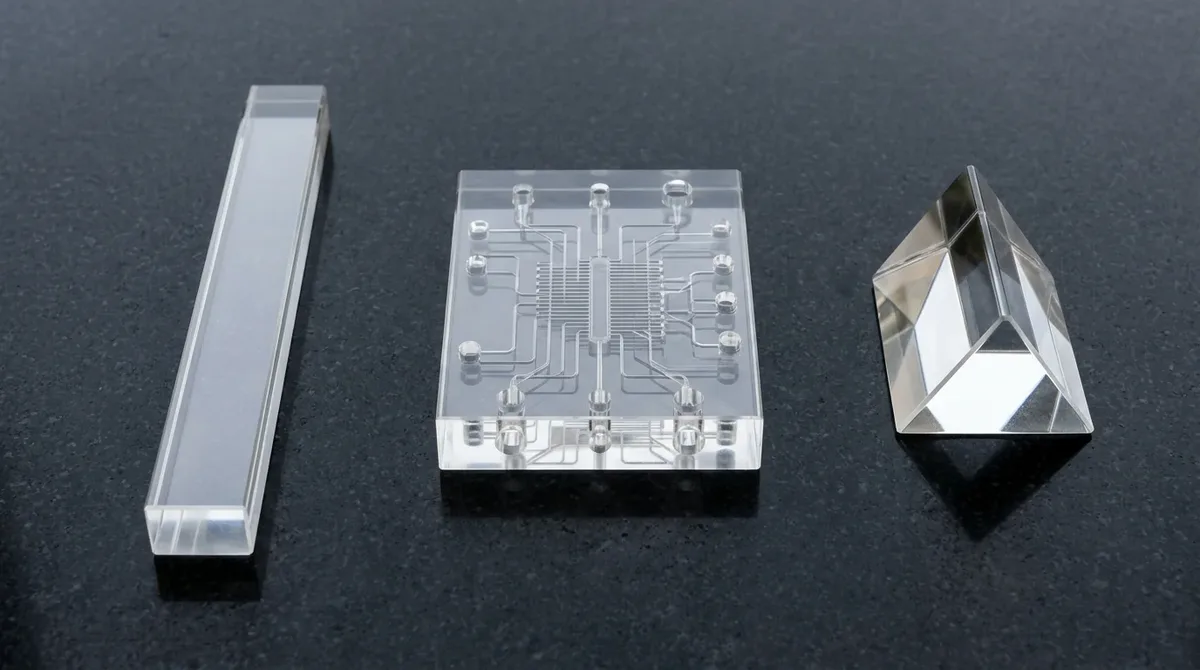
Machining acrylic for clear parts requires an uncompromising mastery of polymer physics, cutting tool micro-geometry, and post-machining surface optical restoration. While polymethyl methacrylate (PMMA) delivers remarkable glass-like optical clarity (92% visible light transmittance) and an Abbe number of 58, its low glass transition temperature (Tg ≈ 105°C) makes it susceptible to localized thermal melting, friction-induced chip rewelding, and micro-crazing. In our specialized precision CNC milling and custom optical lighting prototypes facility, deploying single-crystal diamond tooling, vortex cold-air cooling, single-point diamond flycutting, and progressive buffing protocols enables engineers to produce crystal-clear optical lenses, light pipes, and medical diagnostic manifolds.
⏱️ Estimated Reading Time: ~7 mins | Target Audience: Optical Engineers, Medical Device Designers, Hardware R&D Teams, Precision Sourcing Specialists
⚡ Quick Engineering Takeaways
- Substrate Prerequisite: Cell-cast acrylic (molecular weight > 1,000,000 g/mol) is mandatory for CNC machining; extruded acrylic softens and gums up flutes due to lower molecular density and directional stress.
- Machining Tolerances: Standard milling delivers ±0.025 mm (±0.0010″); precision diamond flycutting on planar faces achieves Ra ≤ 0.010 µm (10 nm) with dimensional stability within ±0.010 mm (±0.0004″).
- Post-Finishing Boundaries: Mechanical SPI A-1 diamond micro-buffing preserves geometric edge datums; flame polishing provides rapid aesthetic clarity but softens edges; solvent vapor polishing is strictly prohibited on PMMA.
- Mandatory Annealing: High-speed cutting generates localized mechanical and thermal shear stresses; soak parts at 80°C to 85°C (1 hr per 5 mm thickness) with controlled cooling (≤ 10°C/hr) to eradicate delayed stress crazing.
1. Optical Physics & Polymer Metallurgy: Why PMMA Dominates Transparent Prototypes
Polymethyl methacrylate (PMMA) is an amorphous thermoplastic resin engineered for exceptional optical clarity, transmitting 92% of incident visible light across 400 nm to 700 nm wavelengths with an Abbe number of 58. While standard soda-lime float glass absorbs light through iron oxide impurities, optical-grade acrylic delivers superior spectral purity, lower density (1.18 g/cm³ versus 2.50 g/cm³ for glass), and remarkable UV radiation resistance without yellowing.
When selecting polymers for transparent prototypes, mechanical and optical design engineers evaluate the refractive index (nd = 1.491) to predict light refraction and total internal reflection (TIR). According to Snell’s Law, the critical angle (θc) at an acrylic-to-air boundary dictates the boundary where light rays reflect entirely within the component without transmission losses:
Snell’s Law Total Internal Reflection Calculation:
θc = arcsin(n_air / n_PMMA) = arcsin(1.000 / 1.491) ≈ 42.12°
Rays striking the internal boundary at angles greater than 42.12° experience total reflection, making cast acrylic the primary polymer for automotive light pipes and optical prisms.
However, achieving this theoretical optical transmission in subtractive prototype manufacturing demands rigorous process controls. Subtractive milling imparts localized shear strain and frictional heat. If peak surface temperatures approach the polymer’s glass transition ceiling (Tg ≈ 105°C), localized molecular chain orientation induces optical birefringence—visible as colorful rainbow fringes under cross-polarized light—and compromises light transmission efficiency.
2. Cast vs. Extruded Acrylic: Selecting the Superior Substrate for CNC Milling
Cell-cast acrylic is the indispensable raw stock substrate for tight-tolerance CNC milling, providing high molecular weight (> 1,000,000 g/mol) that shears into crisp, brittle chips under high-speed cutters. In contrast, extruded acrylic is manufactured through continuous high-pressure extrusion rollers, resulting in lower molecular weight (150,000 to 250,000 g/mol) and significant residual directional orientation.
During milling operations, cutter friction rapidly heats extruded acrylic past its 90°C softening point. The lower molecular density causes the polymer to smear across cutting flutes, weld back onto machined sidewalls, and generate microscopic notch cracks. When exposed to subsequent cleaning solvents or optical buffing compounds, extruded parts experience catastrophic spider-web stress crazing.
| Engineering Property | Cell-Cast Acrylic (PMMA) | Continuous Extruded Acrylic | Optical Polycarbonate (PC) | Cyclic Olefin Copolymer (COC) |
|---|---|---|---|---|
| Light Transmission (%) | 92% – 93% (Crystal Clear) | 90% – 91% (Slight haze) | 88% – 89% (Slight yellow tint) | 91% – 92% (Water clear) |
| Refractive Index (nd) | 1.491 | 1.490 | 1.586 | 1.533 |
| Abbe Number (Vd) | 58 (Minimal chromatic aberration) | 57 | 30 (High chromatic dispersion) | 56 (Low chromatic dispersion) |
| Glass Transition Temp (Tg) | 105°C (221°F) | 95°C (203°F) | 145°C (293°F) | 130°C – 170°C |
| Izod Impact Strength (kJ/m²) | 1.6 – 2.0 (Brittle) | 1.2 – 1.5 | 60 – 75 (Virtually unbreakable) | 1.8 – 2.4 |
| Milling Chip Formation | Crisp, segmented, non-stick | Gummy, strings, prone to rewelding | Continuous ductile ribbons | Crisp chips, low burring |
| Chemical Polish Compatibility | Incompatible with vapor polishing | Catastrophic solvent crazing | Excellent (DCM vapor smoothing) | High chemical resistance |
| Recommended Application | Precision optics, light guides, microfluidics | Non-critical display panels, simple signs | Impact shields, structural covers | Near-UV medical diagnostic cuvettes |
In our Shenzhen facility, every CNC optical project begins with traceable cell-cast PMMA tooling stock. Cell-cast sheets undergo stress-relief cycling prior to squaring, ensuring zero latent internal stress before cutting tools engage the stock.
3. Single-Point Diamond Turning (SPDT) & Single-Flute Tooling for Optical Transparency
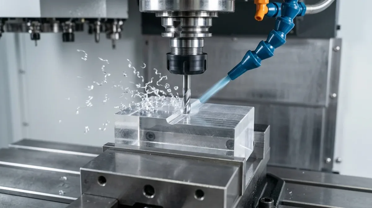
Direct optical transparency on machined acrylic surfaces demands single-point diamond turning (SPDT) flycutting or mirror-polished single-flute carbide tooling that eliminates friction-induced melting. While multi-flute cutters generate excessive friction and re-cut chips in narrow flutes, ultra-sharp single-flute end mills offer expansive chip evacuation troughs, allowing continuous chip clearing before heat conducts into the polymer matrix.
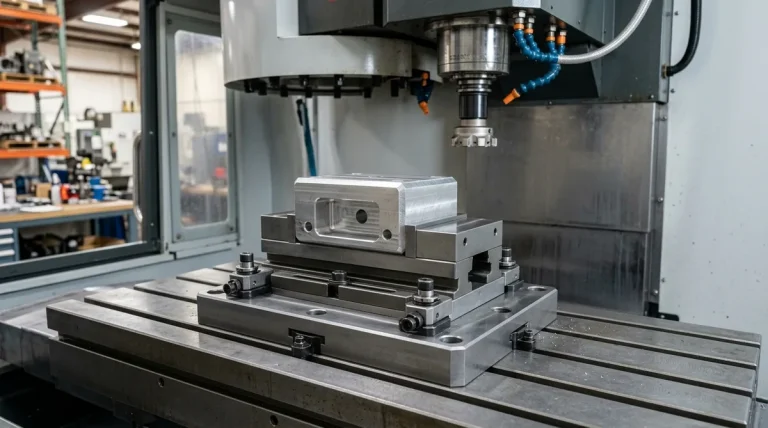
As illustrated in the high-speed vertical machining center setup below, a clear cast PMMA block is securely clamped horizontally in precision vise jaws while a polished single-flute solid carbide end mill executes high-speed surface face milling. A targeted vortex cold-air nozzle directs sub-zero dry air onto the tool-workpiece interface, evacuating curling transparent chips without liquid coolants:
For large planar optical windows, light distribution plates, and diagnostic manifolds, large-diameter flycutter heads fitted with monocrystalline natural diamond (MCD) or polycrystalline diamond (PCD) inserts achieve mirror-like surface roughness values below Ra 0.010 µm (10 nm). Monocrystalline diamond provides an atomic-scale cutting edge radius (r_edge < 5 nm), cleanly shearing acrylic molecular chains without micro-fracturing.
| Machining Operation | Tooling Geometry | Cutting Speed Vc (m/min) | Feed per Tooth fz (mm/tooth) | Axial Depth ap (mm) | Cooling & Chip Evacuation |
|---|---|---|---|---|---|
| Rough End Milling | 2-flute polished carbide end mill | 200 – 350 | 0.06 – 0.12 | 1.00 – 3.00 | Clean compressed air blast |
| Semi-Finish Profiling | Single-flute polished O-flute carbide | 300 – 450 | 0.04 – 0.08 | 0.20 – 0.50 | Vortex cold-air tube (-5°C) |
| Diamond Flycutting (Planar) | Monocrystalline diamond (MCD) insert | 400 – 650 | 0.01 – 0.03 | 0.02 – 0.05 | Vortex sub-zero dry air stream |
| Micro-Channel Milling | D0.2 – D0.5 mm 2-flute micro-carbide | 100 – 180 (40,000 RPM spindle) | 0.005 – 0.015 | 0.02 – 0.05 | Minimum quantity lubrication (MQL) |
In our machine shop practice, we enforce climb milling exclusively on acrylic workpieces. Conventional milling forces the cutter tooth into the chip from a zero thickness up to a maximum exit thickness, creating rubbing and thermal buildup. Climb milling engages at maximum chip thickness and tapers to zero, carrying heat away in the exiting chip and preserving edge clarity.
4. Surface Finishing Protocols: SPI A-1 Diamond Buffing vs. Controlled Flame Polishing
While precision diamond flycutting yields optical transparency on flat surfaces, complex 3D contours, internal cavities, and chamfers require specialized post-machining polishing protocols. Depending on geometric tolerance limits and optical transmission requirements, AS Prototypes deploys mechanical diamond micro-buffing, controlled oxy-hydrogen flame polishing, or optical lapping.
As demonstrated in the precision surface finishing comparison below, two acrylic test blocks illustrate distinct finishing characteristics: the left block showcases SPI A-1 diamond micro-buffing with razor-sharp geometric edges and high optical clarity, while the right block displays flame polishing with glossy surfaces and softened perimeter edges:
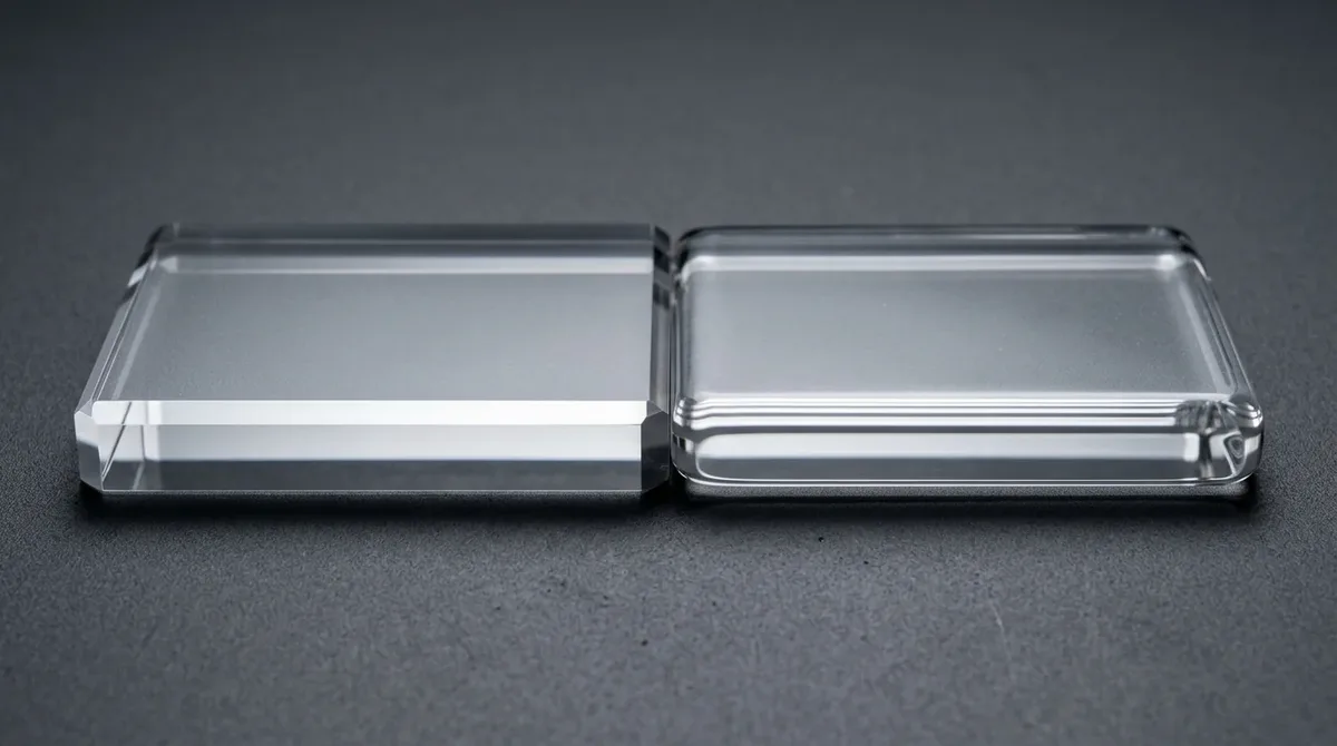
Selecting the optimal polishing protocol requires balancing dimensional precision, optical transmission, and manufacturing cycle time:
- Progressive Mechanical Diamond Buffing (SPI A-1 / A-2 Standards) – The Gold Standard for Precision Geometries. Components undergo progressive wet sanding using silicon carbide abrasive sheets from 400, 800, 1500, up to 3000 grit under constant deionized water lubrication. Parts are transferred to motorized rotary cotton buffs charged with sub-micron diamond polishing compounds (0.5 µm down to 0.1 µm). This physical abrasive method produces true optical clarity without softening critical edge datums or distorting nominal dimensions.
- Precision Oxy-Hydrogen Flame Polishing – Cost-Effective for Flame-Cleared External Edges. A specialized hydrogen-oxygen micro-torch (flame temperature ≈ 2800°C) sweeps across the acrylic surface at a controlled feed rate (150 mm/s to 250 mm/s). The intense localized heat melts the outermost 1 µm to 3 µm layer, utilizing surface tension to level micro-grooves into a high-gloss finish. However, flame polishing rounds sharp corners and induces severe localized surface tensile stress. It is strictly prohibited on parts requiring tight tolerances (±0.020 mm) or fluidic sealing channels.
- Strict Chemical Prohibition: Zero Solvent Vapor Polishing on PMMA – While Polycarbonate (PC) is smoothed using dichloromethane (DCM) vapors, PMMA must never undergo solvent vapor polishing. Solvent vapors attack polymethyl methacrylate polymer chains, dissolving surface bonds, causing immediate stress-whitening, and initiating delayed micro-cracking across all machined contours.
5. DFM Guidelines & Mandatory Thermal Stress-Relief Annealing Protocols
Due to acrylic’s high coefficient of thermal expansion (α ≈ 70 × 10⁻⁶ / K to 77 × 10⁻⁶ / K) and notch sensitivity, successful prototype manufacturing requires strict adherence to Design for Manufacturability (DFM) rules. A mere 5°C shop-floor temperature fluctuation causes significant dimensional expansion on large acrylic parts:
Thermal Expansion Drift Calculation:
ΔL = α · L · ΔT = 75 × 10⁻⁶ / K × 150 mm × 4 K = 0.045 mm (0.0018″)
A 4°C shift produces 0.045 mm of dimensional expansion—exceeding precision optical tolerances (±0.020 mm). This makes climate-controlled machining at 20°C (±0.5°C) essential for micron-level consistency.
When preparing 3D CAD files for CNC acrylic machining, incorporate the following core DFM design rules:
- Generous Internal Corner Radii: Sharp 90° internal corners act as severe stress concentrations. Always specify internal corner radii R ≥ 1.5 mm (0.060″) or R ≥ 1.25 × cutter radius to allow continuous cutter engagement without chatter or localized thermal buildup.
- Nominal Wall Thickness Uniformity: Maintain consistent wall thicknesses between 1.5 mm and 15 mm. Thin ribs below 1.2 mm flex under cutting pressure and vibrate during profiling, causing surface chatter, while overly thick solid blocks (> 30 mm) trap casting stresses that induce warping during rough pocketing.
- Tapped Hole Thread Engineering: Direct fine threading in acrylic is prone to notch failure and stripping. Specify coarse threads (M3 or larger), maintain thread engagement depth at 2.0 × screw diameter, and add a 60° lead-in chamfer to prevent surface chip-out. For repeated disassembly, specify threaded brass or stainless steel ultrasonic/heat-stake inserts.
- Deep Cavity Aspect Ratio: Limit pocket depths to a 3:1 depth-to-width ratio. Deeper pockets require long-reach slender cutters that suffer from tool deflection (δ ∝ L³/D⁴), causing tapered sidewalls and optical hazing.
To eliminate residual stress accumulated during machining, all precision components undergo mandatory oven annealing. Parts are placed in a clean recirculating air furnace and heated to 80°C–85°C (below the 105°C Tg), soaked for 1 hour per 5 mm of cross-section thickness, followed by gradual cooling at ≤ 10°C/hour down to ambient temperature. This protocol relieves frozen molecular shear stresses and guarantees dimensional stability over years of service.
6. Why Does Machined Acrylic Suffer from Stress Crazing and Hazing?
Stress crazing in machined acrylic is caused by localized residual tensile stress exceeding the polymer’s critical crazing threshold (σ_crit ≈ 15 to 20 MPa), accelerated by micro-notch defects or solvent exposure. When external tensile loads or machining stresses orient polymer chains, microscopic voids form and coalesce into visible reflective fissures called crazes.
In precision manufacturing, crazing typically manifests after machining when parts contact volatile solvents like isopropyl alcohol (IPA), acetone, or threadlocking compounds. Because alcohol acts as a plasticizing agent, it lowers the crazing stress threshold by over 60%, causing instant catastrophic spider-web cracking.
Shop-Floor Failure Investigation: Stress Crazing Around Milled Fluid Ports
- Symptom: Microscopic radial cracks developed around drilled fluidic inlet ports of 50 diagnostic manifolds 48 hours after final ultrasonic cleaning.
- Root Cause: High feed rates during hole drilling induced mechanical hoop stress; the cleaning technician wiped parts with 99% isopropyl alcohol before the mandatory thermal annealing cycle was performed.
- Corrective Action: Mandated peck-drilling with polished single-flute tooling under vortex cold air, strictly prohibited alcohol wipe-downs (replaced with deionized water and mild surfactant), and enforced an 82°C / 4-hour annealing cycle prior to final assembly. Zero crazing failures recurred across 1,200 subsequent units.
7. High-Precision Applications: Microfluidics, Optical Prisms & Light Pipes
Machined optical acrylic components serve mission-critical roles across biotechnology, medical diagnostics, automotive lighting, and scientific instrumentation where glass is too brittle or injection molding tooling is cost-prohibitive for low-volume production.
As captured in the extreme macro photograph below, a precision CNC micro-milled cast PMMA microfluidic diagnostic chip manifold rests flat on an inspection plate, displaying intricate 150-micron wide fluid channels, serpentine mixers, and circular reservoir ports machined with optical wall smoothness:
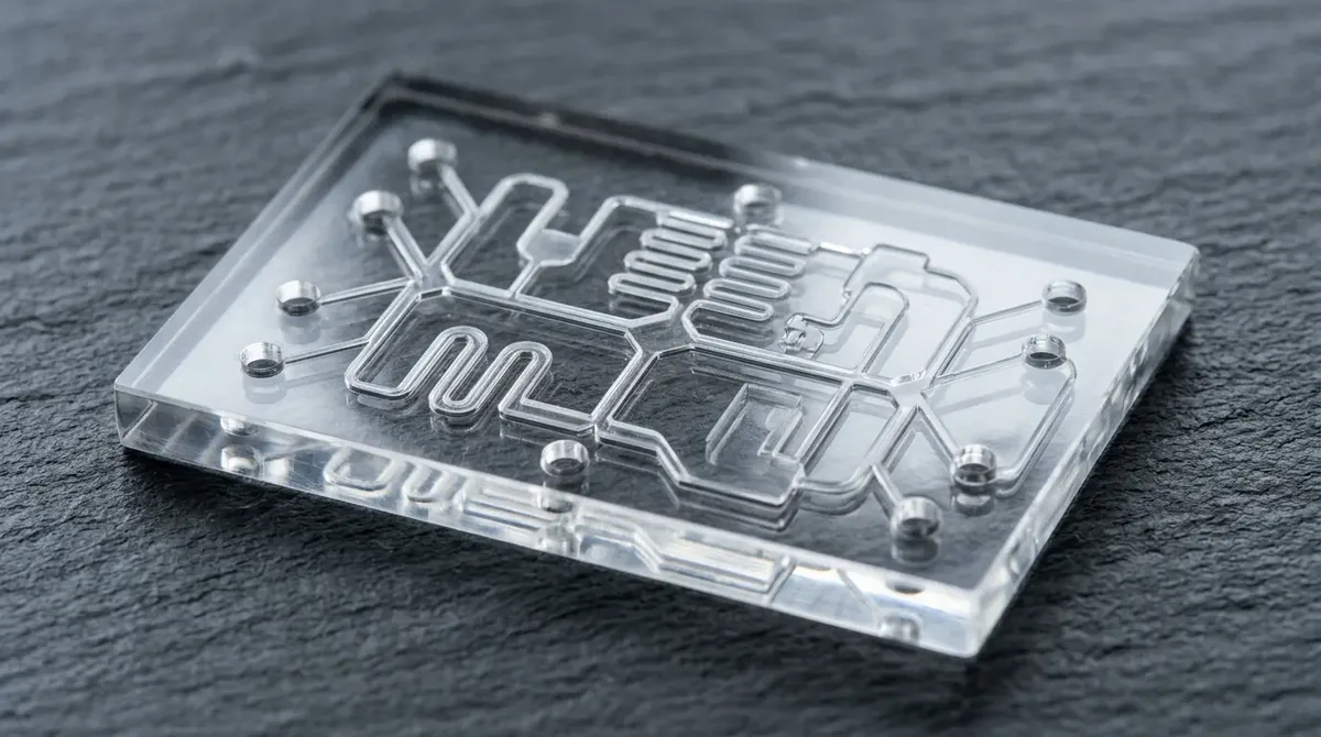
In our medical prototyping lab, microfluidic chips feature micro-end-milled fluid channels with cross-sections down to 100 µm × 100 µm. The chips are sealed using solvent diffusion bonding or thermal press bonding at 98°C, creating hermetic diagnostic cartridges for DNA sequencing, point-of-care blood analysis, and droplet generation.
In the automotive and commercial illumination sector, optical PMMA acrylic provides high optical performance for light transmission. For further engineering details on complex optoelectronic assemblies, consult our comprehensive guide on CNC acrylic machining feeds and speeds.
As illustrated in the optical test photograph below, a collimated light beam passes cleanly through a precision CNC machined and diamond-polished acrylic prism and rectangular light guide resting flat on a dark granite stage, demonstrating total internal reflection with pure 92% transmission and zero stress-induced birefringence:
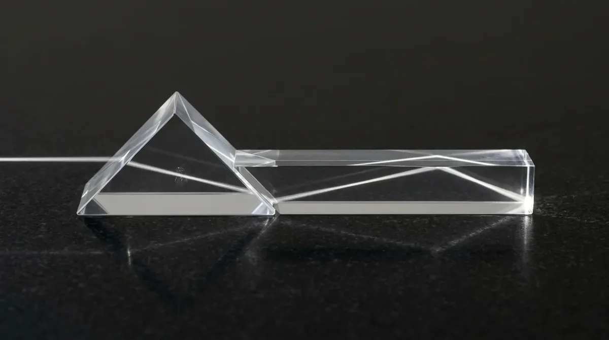
By engineering faceted internal reflection angles matching Snell’s critical limit (θc ≈ 42.12°), optical light pipes guide high-flux LED illumination from circuit boards across complex 3D dashboards with zero chromatic distortion.
8. When NOT to Choose Acrylic: Material Limitations & Engineering Trade-offs
While polymethyl methacrylate delivers exceptional optical transparency and machinability, it is not an all-purpose polymer. Rigorous engineering requires recognizing PMMA’s physical and mechanical boundaries:
- Severe Notch Sensitivity & Low Impact Resistance: With an Izod notched impact strength of only 1.6 to 2.0 kJ/m², acrylic is inherently brittle. High-stress shock loads, dropped assemblies, or overtightened mechanical fasteners induce fast-propagating catastrophic fracture. When impact resistance is the priority, engineers must specify Optical Polycarbonate (PC) (Izod impact > 60 kJ/m²).
- Moderate Thermal Ceiling: PMMA exhibits a glass transition temperature (Tg) of 105°C and a heat deflection temperature of 100°C under 0.45 MPa load. The maximum continuous operating temperature is limited to 75°C to 80°C. For transparent housings operating near high-power LEDs or engines, optical PC or Cyclic Olefin Copolymers (COC/COP) are required.
- Vulnerability to Solvents and Cleaning Agents: PMMA dissolves or crazes rapidly when exposed to acetone, benzene, ethyl alcohol, methyl ethyl ketone (MEK), and thinners. If components require harsh chemical sterilization (e.g., autoclaving, ethylene oxide, or hydrogen peroxide plasma), acrylic will haze; specify Cyclic Olefin Copolymer (Topas/Zeonex) or Polysulfone (PSU) instead.
- Scratch Vulnerability: With a pencil hardness of approximately 3H (Rockwell M90), raw acrylic scratches easily during handling. While scratches can be mechanically re-buffed, optical components exposed to outdoor environments require secondary optical silicone or polysiloxane anti-scratch hardcoats.
9. Engineering Verdict: Material & Process Selection Matrix
To assist hardware teams in making definitive manufacturing decisions, our engineering team has synthesized a shop-floor decision matrix based on primary application priorities:
Decision Tree: Material & Finishing Selection
- Maximum Optical Clarity & Minimal Chromatic Aberration: Choose Cell-Cast PMMA Acrylic with single-point diamond flycutting for planar faces, followed by SPI A-1 mechanical diamond micro-buffing and an 80°C stress-relief annealing cycle.
- Impact Resistance & Structural Toughness: Choose Optical Polycarbonate (PC). Utilize dichloromethane (DCM) solvent vapor smoothing for complex internal contours where buffing wheels cannot reach.
- Microfluidic Diagnostic Chips with Near-UV Fluorescence: Choose Cell-Cast PMMA for standard optical diagnostics, or upgrade to Cyclic Olefin Copolymer (COC) if minimal autofluorescence and high chemical resistance are required.
- Rapid Edge Deburring on Display Windows: Utilize Oxy-Hydrogen Flame Polishing on cell-cast acrylic when cycle time is critical and tolerances are relaxed (±0.10 mm).
- High-Temperature Transparent Enclosures (> 90°C): Specify Optical Polycarbonate (PC) or Polysulfone (PSU); avoid PMMA due to thermal softening and dimensional creep.
Frequently Asked Questions
Cell-cast acrylic features a high molecular weight exceeding 1,000,000 g/mol, which produces crisp, brittle chips under high-speed cutting without melting or gumming cutter flutes. Extruded acrylic possesses a lower molecular weight (150,000 to 250,000 g/mol) and directional stress, making it prone to thermal softening, chip rewelding, and delayed stress crazing.
Optical clarity is achieved on planar surfaces using Single-Point Diamond Turning (SPDT) flycutting to achieve Ra below 0.010 µm (10 nm). For 3D contours and pockets, parts undergo multi-stage wet sanding (400 to 3000 grit) followed by rotary buffing with 0.5 µm diamond paste. Unlike Polycarbonate, PMMA strictly avoids chemical solvent vapor smoothing to prevent stress crazing.
High-speed CNC milling induces localized mechanical and thermal shear stresses within the acrylic substrate. Without oven annealing (heating at 80°C to 85°C and cooling slowly at ≤ 10°C/hr), residual stresses exceed the critical threshold, causing parts to develop spider-web micro-cracks (crazing) when exposed to environmental humidity, UV light, or cleaning agents.
Yes, oxy-hydrogen flame polishing rapidly levels surface micro-grooves by melting the top sub-micron layer, creating a high-gloss finish on external edges. However, flame polishing rounds sharp corners and induces high localized surface tensile stress. It must never be used on parts requiring tight tolerances (±0.020 mm) or mating microfluidic sealing surfaces.
Machining acrylic requires ultra-sharp, mirror-polished single-flute solid carbide end mills (O-flute) with high rake angles to provide generous chip clearance. Vortex cold-air guns delivering dry sub-zero air (-5°C) are used to evacuate chips without liquid coolants, maintaining cutting zone temperatures well below acrylic’s 105°C glass transition ceiling.
Precision Machined Optical Acrylic Prototypes & Manifolds
From crystal-clear optical lenses and automotive light pipes to sealed microfluidic diagnostic chips, our facility delivers micron-accurate PMMA machining with diamond flycutting and precision optical buffing. Upload your 3D CAD files (STEP/IGES) for a rapid engineering quote and DFM review.