Metal machining, particularly milling, is extensively used in contemporary prototyping methods. Prototype manufacturers strive to fully utilize their equipment’s technological capabilities. One method that has gained popularity in recent years is helical milling. Let’s explore what helical milling entails, its advantages and disadvantages, and how you can leverage this knowledge to reduce manufacturing costs when designing your prototype.
What Is Helical Milling?
Helical milling is an alternative hole-making process where an endmill follows a helical path to produce high-quality bores. This method offers several advantages over conventional drilling and can even replace boring machines, which is beneficial for prototyping shops looking to minimize equipment purchases. Helical milling can create bores of nearly any shape, with lower cutting forces and reduced tool wear, while achieving high-quality results.
Why not drilling?
The main alternative to helical milling is conventional drilling, a widely used method for creating holes. Statistically, drilling accounts for up to 25% of cycle time and 33% of the total number of machining operations when manufacturing a metal part. However, why should you consider milling? Despite its simpler kinematics, drilling has several drawbacks that justify the use of the more complex milling technique.
For instance, drilling speed varies with the diameter. It is highest at the outer edge and nearly zero at the center of the drill (where the axis is). This means that the machining process near the axis involves more plastic deformation than actual cutting, increasing the tool’s thrust force and accelerating tool wear.
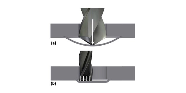
Additionally, due to the axial thrust force, a drill—especially a worn one—can bend a thin layer of metal as it exits the stock, leaving behind protruding material around the hole that needs to be removed manually. Using a mill instead significantly reduces this leftover material.
Drilling presents significant challenges in chip removal. The processed material can only be evacuated through the drill flutes, which affects the surface finish of the hole and the cutting temperature. As metal chips move from the cutting zone through the flutes to the surface, they scrape the sides of the hole, diminishing the surface quality. Additionally, research shows that chips carry away up to 80% of the cutting heat. Therefore, poor chip removal increases the drill’s temperature, accelerating tool wear.
To improve chip removal, operators often use discrete drilling methods, where the drill cuts a portion of the hole’s length and is then withdrawn. While this strategy enhances chip removal, it also increases the drilling time.
Given these drawbacks, manufacturers are increasingly adopting helical milling to boost machining efficiency and, consequently, the efficiency of prototyping shops.
Some helical milling specifics
Let’s examine some of the processes involved in helical milling.
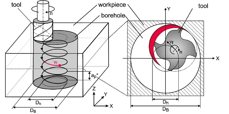
Firstly, the end mill follows a helical path, requiring the milling center to combine vertical movement along the z-axis with horizontal movement along the x-y axis. This complexity makes the NC program challenging to write manually. However, many CAM systems have integrated helical milling as one of their strategies.
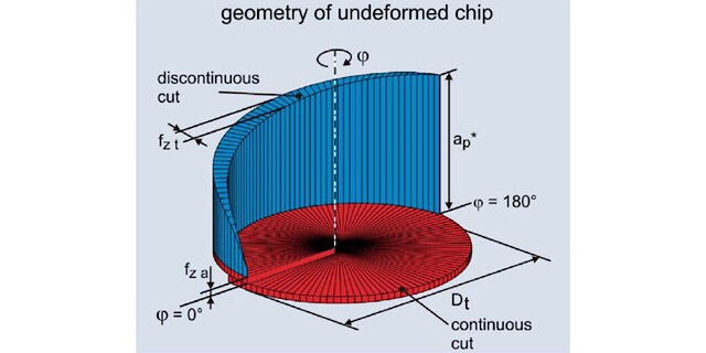
The chip geometry in helical milling consists of two zones: the blue zone, created by the side of the end mill, and the red zone, generated by the face of the mill. It has been demonstrated that the ratio between these two zones is determined solely by the tool and bore diameters.
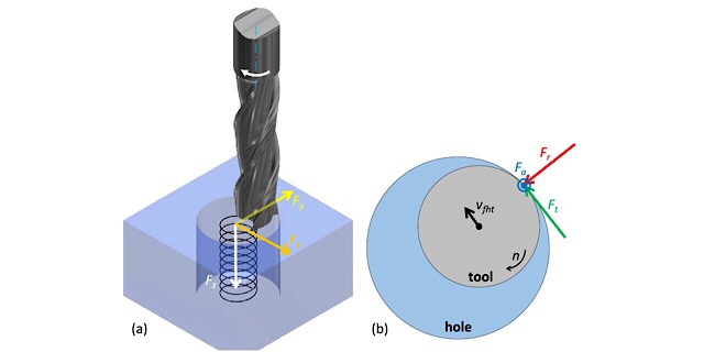
As the tool diameter increases, the blue zone also expands. This leads to poorer milling in terms of vibration, as the blue chip is discontinuous, unlike the red chip. Consequently, the surface finish will be worse. Additionally, as the volume removed by the side of the mill increases, radial cutting forces (denoted as red 𝐹𝑟Fr in the diagram) also grow, causing the tool to bend inside the hole and reducing tolerance. However, this negative effect is somewhat mitigated by the increased rigidity of larger tools.
Conversely, if the tool is smaller, the red zone dominates, resulting in smaller radial forces and less vibration. However, the reduction in tool diameter is limited by the system’s rigidity.
A practical approach would be to use a larger tool initially and then switch to a smaller one for a final cut with low depth and feed. This method can achieve a superior surface finish.
Reasons to use helical milling
As you can see, helical milling is a promising process that offers numerous advantages.
Firstly, you can achieve any diameter with better precision and surface quality without changing the tool. If you’ve ever drilled a hole larger than 35 mm, you know that using a single drill is not ideal. Typically, you start with a smaller drill, say 10 mm, then use a larger drill to expand the hole to 20 mm, and finally to 35 mm. For higher precision or better surface finish, additional steps like reaming or countersinking are required, involving 4-6 tool changes. With helical milling, however, you only need one endmill to cut the hole, and then you can use a smaller feed to achieve the desired tolerance and quality. You can reach up to IT7 with an Ra of 1.25 without changing tools.
Secondly, helical milling offers lower cutting temperatures and better chip removal. The endmill does not occupy the entire bore space, which is a significant advantage. You don’t need to retract the tool after plunging every 30 mm or so. Simply spraying coolant into the hole will help remove chips and lower the machining temperature.
Lastly, helical milling allows for better prediction of tool wear and trajectory modifications. One of the main issues with drilling is that tool wear is often only noticeable once the drill is completely worn out or broken, especially when machining hard materials. In such cases, the drill can even get stuck in the bore. With helical milling, you are essentially milling, which means you can predict tool wear using standard calculation methods or the tool life specified by the manufacturer. You can also adjust the trajectory during the process to maintain the diameter dimension, something that’s not feasible with drilling. Additionally, tool life in helical milling is determined by the face wear of the tool (red zone chip).
Conclusions
Of course, helical milling is an innovative process and it has its drawbacks. For instance, its chip removal rate isn’t as fast, and its parameters are not yet thoroughly researched. However, this technique reduces the number of setups, machining operations, and tooling required, while maintaining high-quality bores. This is a significant advantage for prototyping manufacturers who aim to minimize the amount of tooling and equipment needed.