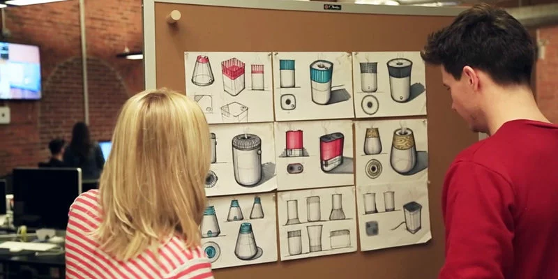
Seeing is believing, and hands-on experience is invaluable. While skipping the prototyping phase in design might seem like a time-saver, it often leads to longer delays during development. Just as we try on clothes before buying or take a car for a test drive, it’s wise to validate your design with prototype parts before advancing to the development stage.
CNC Machining for Prototype Parts
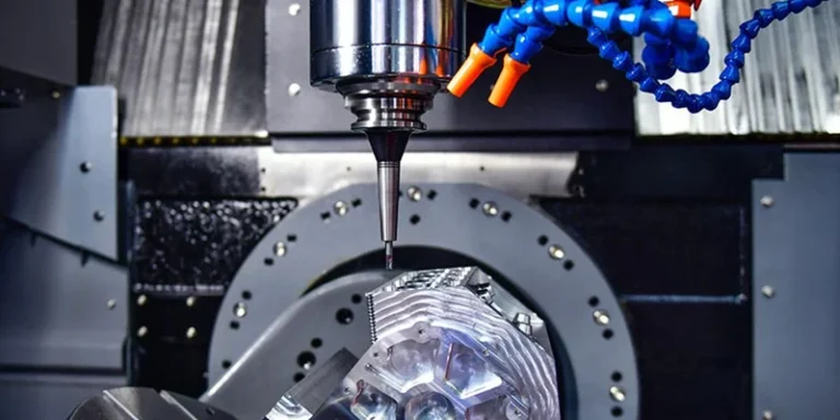
There isn’t a one-size-fits-all solution for creating prototypes, as the choice of process depends on specific project requirements. One commonly used method in rapid prototyping is CNC machining, which involves subtractive manufacturing, unlike 3D printing. When a supplier receives a project, they typically follow these steps:
Analyze Processing Drawings and Determine the Machining Process
The first step involves a detailed analysis of the processing drawings provided by the customer. This includes assessing the part’s shape, dimensional accuracy, surface finish, material, blank type, and heat treatment status. Based on this analysis, the appropriate machine tools and cutting tools are selected, along with determining the positioning and clamping devices, processing methods, sequences, and cutting parameters. It’s crucial to consider the capabilities of the CNC machine tool, maximizing its efficiency by establishing an optimal processing route with minimal passes and reduced processing time.
Accurately Calculate Tool Path Coordinates
The next step is to calculate the tool path coordinates based on the part’s geometrical dimensions and the programmed coordinate system. This involves determining the motion track of the tool path center to gather all necessary tool position data. CNC systems typically offer linear and circular interpolation functions. For simple shapes, such as those composed of straight lines and arcs, only key points like the starting and ending points, arc centers, intersections, or tangent points need to be calculated.

If the CNC system lacks a tool compensation function, the coordinate values for the tool center’s motion path must be calculated manually. For parts with complex shapes, such as those featuring non-circular curves and curved surfaces, straight lines or arc segments are used to approximate the actual curves or surfaces. The coordinates of these nodes are then calculated to meet the required machining accuracy.
Write the CNC Machining Program
Once the tool path, movement data, and process parameters are determined, the programmer writes the CNC machining program. This involves using the function instructions and block format specified by the CNC system. The program should be clear and easy to understand, facilitating communication. It’s important for the programmer to be thoroughly familiar with the CNC machine’s performance and instructions, using the appropriate techniques and skills for each program segment.
Purchase Materials
The next step is to acquire the necessary materials, which generally include metals and plastics. Common metals used are aluminum, stainless steel, sheet metal, magnesium alloy, and titanium alloy. For plastics, materials like ABS, PMMA, PC, PP, and POM are typically used.
CNC Machining Process
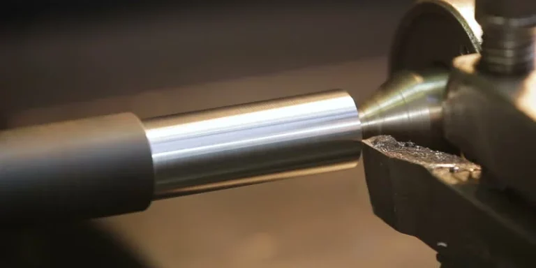
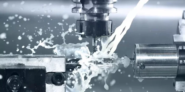
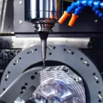
The machining process begins with a rough cut, using a larger tool to quickly remove significant amounts of material within the machine’s power and tool tolerance limits. It’s crucial to check for any loosening of the workpiece due to cutting vibrations and re-align if necessary. For workpieces with complex cavities, the initial roughing may leave residual material in corners. Secondary roughing or corner cleaning with smaller tools may be needed. In larger machining areas, semi-finishing can help reduce tool wear. To avoid overcutting, leave a sufficient margin for the final finishing process. Typically, the workpiece is checked on the machine tool, removed after passing inspection, and then prepared for the next stage of processing.
Finishing
After CNC machining, a variety of finishing options are available to enhance the surface quality of parts. These include manual cornering, sandblasting, polishing, painting, silkscreening, plating, and oxidation.
- Cleanup Corners: CNC machining often leaves structural corners that need manual chiseling with specific tools to ensure proper fit and assembly.
- Smoothing: This surface treatment involves polishing the prototype parts to remove burrs and tool marks. Different grades of sandpaper are used, with lower numbers indicating coarser sand and higher numbers indicating finer sand.
- Polishing: Materials like PMMA and PC are polished to achieve a transparent or mirror-like finish.
- Sandblasting: This process removes small burrs and creates a textured surface, preparing it for further processing and enhancing surface durability.
- Painting: Spray painting provides both protective and aesthetic benefits, with colors matched to customer specifications using Pantone or RAL numbers.
- Silkscreening: Used for printing logos, allowing for color customization.
- Plating: Electrolysis attaches a metal film to surfaces, preventing oxidation, enhancing wear resistance, and improving appearance.
- Oxidation: This process improves the hardness and wear resistance of aluminum alloys, extending their application range and service life.


Summary
CNC machining is a widely utilized method for creating prototypes, known for its precision and versatility. As a leading prototype manufacturer, AS Prototypes excels in delivering high-quality CNC machined parts with short lead times, tight tolerances, and competitive pricing. Contact us for any inquiries.

