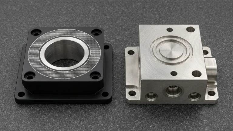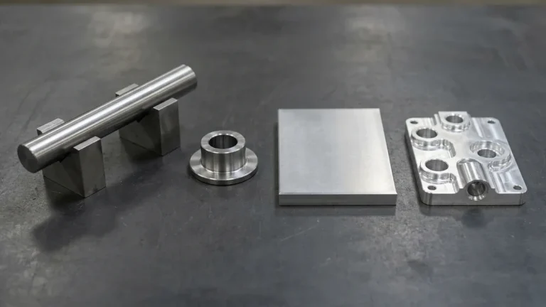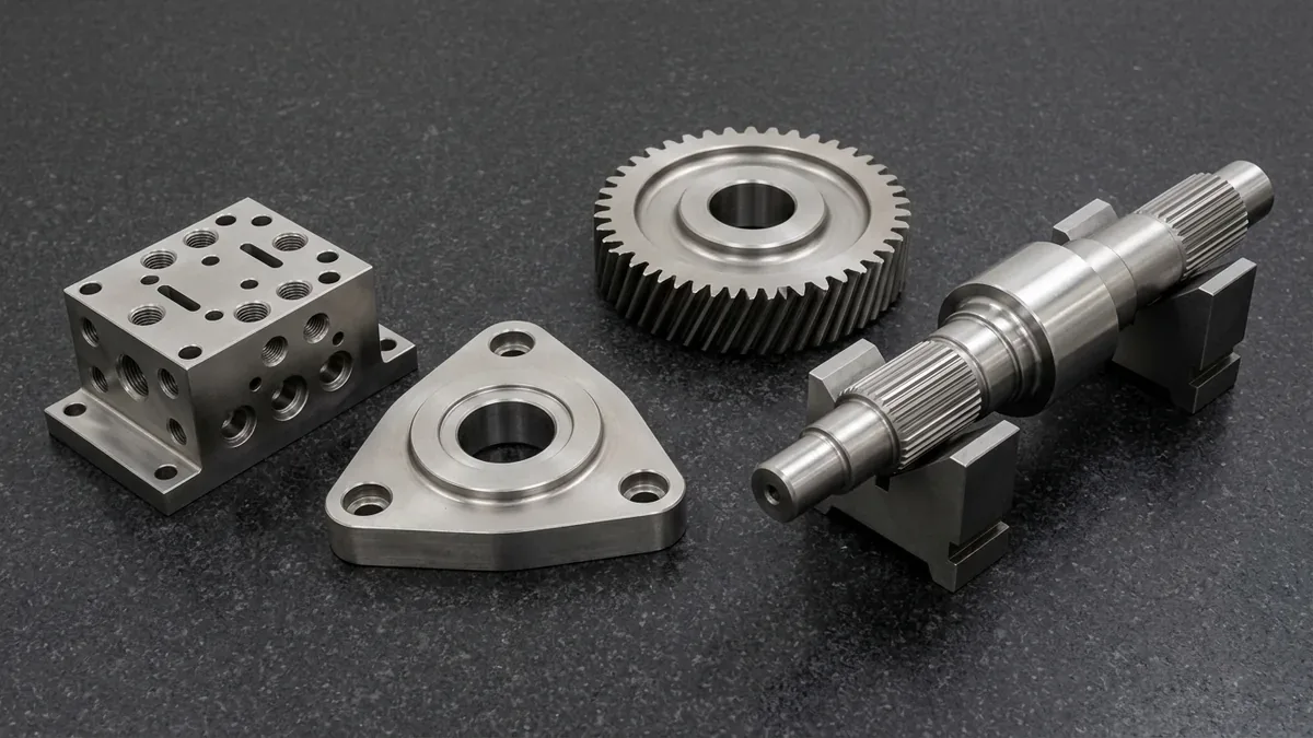
Precise metallurgical control through heat treatment for CNC machining transforms raw alloy billets into high-end structural components capable of withstanding extreme dynamic fatigue, frictional abrasion, and high impact stresses. However, improper thermal cycling can introduce severe quench distortion, volumetric phase expansion, and micro-cracking that destroy tight drawing tolerances. At our in-house facility, our materials engineers combine vacuum furnaces, controlled-atmosphere nitriding, and cryogenic stabilization with advanced precision CNC machining services and functional industrial surface finishing solutions to ensure parts maintain dimensional stability within ±0.005 mm when combined with post-heat-treatment precision grinding or wire EDM finishing.
- 1. Phase Transformation Metallurgy: From Ferrite to Martensite
- 2. Quenching Dynamics & Distortion Mechanisms
- 3. Tempering & Sub-Zero Cryogenic Stabilization
- 4. Precipitation Hardening in Aerospace Aluminum & PH Stainless Steels
- 5. Surface Case Hardening: High Wear Shell with Ductile Core
- 6. Post-Hardening CNC Machining: Hard Milling Strategies
- 7. Precision Grinding for Quench Distortion Remediation
- 8. Shaft & Rotational Symmetry Distortion Control
- 9. Zero-Cutting-Force EDM for High-Hardness Geometries
- 10. Quality Control, Hardness Verification & Metrology Standards
- 11. Heat Treatment & Machining Matrix for Common Engineering Alloys
- 12. DFM Rules: Engineering CAD Models to Prevent Thermal Distortion
- 13. Technical Engineering FAQ
1. Phase Transformation Metallurgy: From Ferrite to Martensite
Heat treatment alters the crystalline arrangement of metallic grains without melting the workpiece. In iron-carbon steel alloys, thermal processing manipulates allotropic phase transformations between ferrite, austenite, and martensite:
- Austenitizing Kinetics: Heating alloy steel above the upper critical transformation line (Ac3, typically 800°C to 1050°C depending on carbon and alloy content) dissolves iron carbides into face-centered cubic (FCC) austenite. In this high-temperature phase, carbon atoms distribute uniformly throughout the solid solution.
- Martensitic Transformation Shear: When the austenitized steel is rapidly quenched past its critical cooling velocity, carbon atoms lack sufficient time to diffuse into equilibrium ferrite and cementite. Instead, the crystal lattice shears through a diffusionless transformation into body-centered tetragonal (BCT) martensite. This entrapment creates intense internal lattice strain, yielding extreme macro-hardness (up to 64 HRC) alongside significant volumetric expansion (approximately 3% to 4%), which is the primary root cause of thermal quench distortion.
- Transformation Kinetics (CCT & TTT Curves): Continuous cooling transformation (CCT) diagrams dictate the minimum cooling rates required to bypass the intermediate pearlitic and bainitic “noses.” Highly alloyed tool steels (such as AISI D2 and S136) possess elevated hardenability, enabling through-hardening even during relatively gentle pressurized gas quenching, whereas low-alloy carbon steels require aggressive oil or polymer quenching that exacerbates thermal stress gradients.
- Retained Austenite Risks: High-carbon and high-alloy tool steels exhibit martensite finish (Mf) temperatures well below ambient room temperature. As a result, conventional room-temperature quenching leaves between 5% and 18% unstable retained austenite trapped within the grain boundaries. Over months of service or thermal cycling, this metastable austenite spontaneously transforms into fresh un-tempered martensite, causing progressive dimensional growth, loss of straightness, and micro-cracking in precision sliding components.
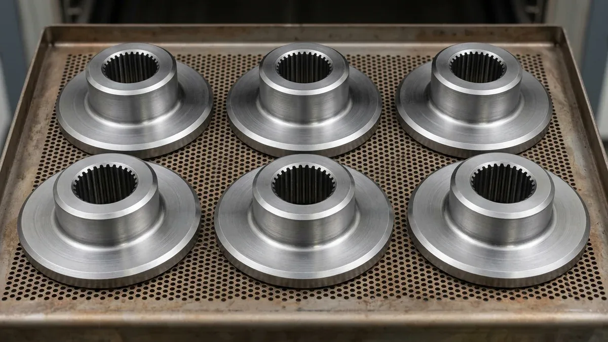
2. Quenching Dynamics & Distortion Mechanisms
The transition from furnace soaking to ambient temperature generates two opposing stress fields inside CNC machined geometry: thermal stresses and transformation stresses.
- Thermal Contraction Gradients: During the initial seconds of quenching, thin outer walls and exposed edges cool rapidly and contract while the thicker core remains hot and expanded. This thermal differential induces transient tensile stresses on the skin and compressive stresses at the center.
- Phase Expansion Inversion: As the outer perimeter reaches the martensite start (Ms) temperature, it expands volumetrically while the core is still contracting. When the core finally transforms to martensite at a later time, it expands against the already rigid, hardened outer shell, reversing the internal residual stress profile.
- Quenching Medium Trade-offs:
- Vacuum High-Pressure Gas Quenching (10 to 15 bar N2): Delivers uniform heat extraction across complex prismatic parts. Minimizes thermal shock and distortion, making it ideal for high-hardenability mold and die steels.
- Accelerated Quench Oil: Provides intense cooling rates necessary for medium-carbon alloy steels (such as AISI 4140 and 4340). However, the unstable vapor blanket (Leidenfrost phenomenon) can cause localized cooling disparities and asymmetrical warping.
- Polymer Quenchants: Water-soluble polyalkylene glycols (PAG) eliminate the vapor phase and provide tailorable cooling rates between water and oil, extensively utilized for distortion control in aerospace aluminum billets.
3. Tempering & Sub-Zero Cryogenic Stabilization
As-quenched martensite is brittle and saturated with residual tensile stress. Subsequent tempering and cryogenic cycles are vital to establish dependable operational ductility and dimensional permanence:
- Low-Temperature Tempering (150°C – 250°C): Precipitates coherent transition epsilon-carbides, relieving peak macro-stresses while retaining peak surface hardness (58 – 62 HRC) for cutting tools and cold-forming dies.
- High-Temperature Tempering (500°C – 650°C): Facilitates secondary hardening in alloy tool steels containing chromium, molybdenum, and vanadium through the precipitation of stable sub-microscopic carbides, optimizing fracture toughness and fatigue resistance for dynamic shafts and structural forgings.
- Sub-Zero & Deep Cryogenic Treatment (DCT): Transferring quenched parts into an environmental cryo-chamber at -80°C (dry ice/alcohol) or -196°C (liquid nitrogen vapor) drives the steel below its martensite finish (Mf) temperature. This process converts up to 98% of retained austenite into stable martensite. Concurrently, cryogenic thermal contraction induces lattice micro-strains that precipitate ultra-fine eta-carbides, dramatically increasing wear resistance and preventing long-term micro-scale dimensional drift.
- Stress Relief Annealing Between CNC Operations: Rough machining imparts severe plastic deformation and surface residual stresses into the raw billet. Soaking semi-finished steel components at 550°C to 650°C followed by slow furnace cooling (or alloy-specific intermediate stress relief for aluminum: 150°C–165°C for 6061-T6 and ≤100°C–110°C for 7075-T651 to prevent over-aging) relaxes internal machining stresses, ensuring the part does not warp during subsequent finish milling or hardening.
4. Precipitation Hardening in Aerospace Aluminum & PH Stainless Steels
Unlike carbon steels that harden through phase transformation, non-ferrous and precipitation-hardening alloys achieve extreme mechanical performance through solid-state precipitation:
- Aerospace Aluminum (6061-T6 and 7075-T651): Solution heat treatment at 470°C to 530°C dissolves magnesium, silicon, and zinc into solid solution. Following rapid water quench within 5 seconds, plates designated as T651 undergo mechanical stretching by 1% to 3% permanent set. This stretching mechanically neutralizes non-uniform quenching stresses, preventing plate potato-chipping during aggressive pocket milling. Subsequent artificial aging at 120°C to 175°C precipitates coherent Guinier-Preston (GP) zones and sub-microscopic Mg2Si or MgZn2 intermetallic phases, doubling tensile yield strength.
- 17-4PH (AISI 630) Precipitation Hardening Stainless: Shipped in Condition A (solution treated at 1040°C, martensitic structure), 17-4PH is easily machined in its annealed state. Components then undergo a simple single-step aging cycle (e.g., Condition H900 at 480°C for 1 hour or H1150 at 620°C for 4 hours) to precipitate highly dispersed copper-rich clusters. Because this thermal cycle involves no high-temperature austenitizing or liquid quenching, 17-4PH achieves hardnesses up to 44 HRC with near-zero volumetric shrinkage (<0.05%), preserving precision CNC milled datum features.
5. Surface Case Hardening: High Wear Shell with Ductile Core
When components endure combined high sliding friction, surface Hertzian contact fatigue, and cyclic torsional shock, case hardening outperforms through-hardening by engineering a hard outer shell over a shock-absorbing ductile core:
| Surface Hardening Method | Process Temperature | Typical Case Depth | Surface Hardness | Distortion Risk & Post-CNC Remediation |
|---|---|---|---|---|
| Gas / Vacuum Carburizing | 880°C – 950°C | 0.5 – 2.5 mm | 58 – 62 HRC | High thermal distortion due to oil/gas quench; requires 0.3–0.5 mm post-grind stock allowance. |
| Plasma (Ion) Nitriding | 480°C – 540°C | 0.1 – 0.6 mm | 65 – 72 HRC (1000+ HV) | Near-zero distortion; sub-critical process without phase transformation or liquid quench. Ideal for finished CNC parts. |
| Carbonitriding | 800°C – 870°C | 0.2 – 0.8 mm | 60 – 64 HRC | Moderate distortion; nitrogen additions enhance hardenability, permitting milder oil quench. |
| Induction Hardening | Localized HF heating | 1.0 – 5.0 mm | 54 – 60 HRC | Localized thermal input; core remains unheated. Excellent for cylindrical bearing journals and gear teeth. |
6. Post-Hardening CNC Machining: Hard Milling Strategies
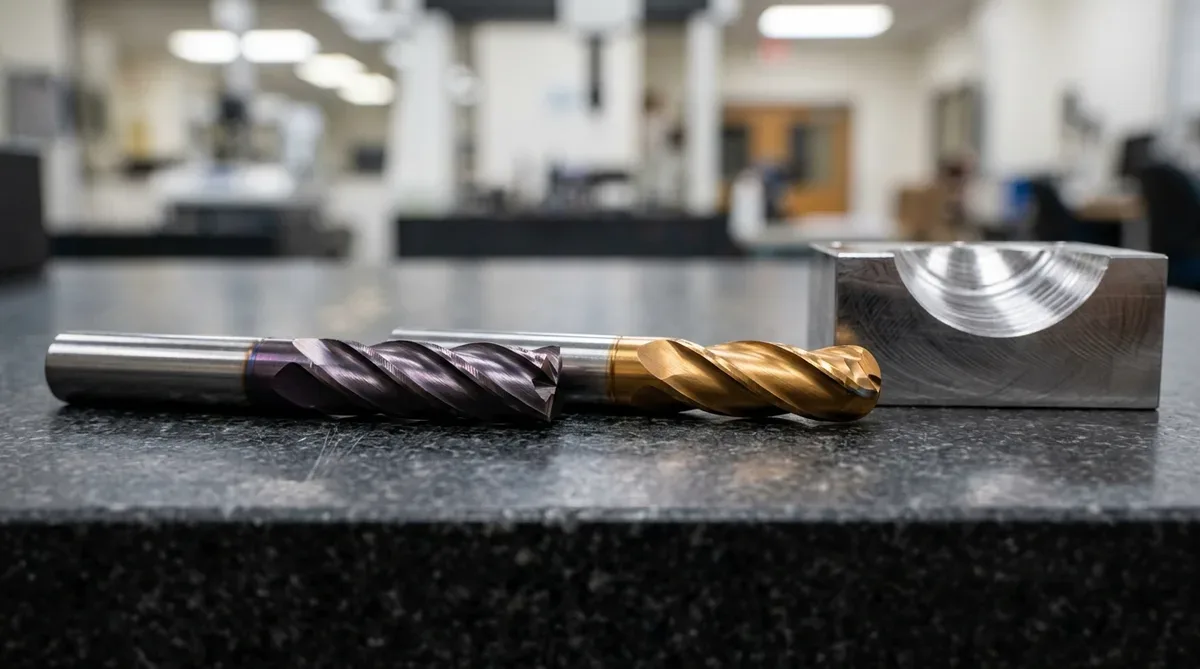
Modern CNC machining centers equipped with high-torque, high-speed spindles and rigid tooling allow direct hard milling of fully quenched tool steels (up to 62 HRC), eliminating intermediate soft-machining cycles in prototype tooling:
- Cutting Tool Substrates: Standard cobalt carbide tools fail rapidly when cutting hardened martensitic matrixes. Hard milling utilizes sub-micron grain tungsten carbide substrates with high cobalt-ruthenium binders, coated with multi-layer nano-composite coatings such as AlTiN, AlCrN, or TiSiN capable of resisting oxidation temperatures up to 1100°C. For continuous finishing above 60 HRC, solid polycrystalline cubic boron nitride (cBN) inserts provide supreme thermal chemical inertness.
- Toolpath Kinematics & Chip Evacuation: Hard milling generates intense localized frictional heat (temperatures exceeding 800°C at the shear plane). To avoid catastrophic thermal shock and micro-chipping of the cutting edge, flood coolant is strictly avoided. Instead, high-pressure dry air blast or minimum quantity lubrication (MQL) is deployed to evacuate incandescent micro-chips instantly from the cutting path.
- Spindle Rigidity & Workholding: Utilizing 5-axis CNC machining centers with dual-contact BBT or HSK-A63 spindle tapers dampens cutting chatter. Machined components are held rigidly in high-pressure hydraulic modular vises, utilizing custom-profiled aluminum or hardened soft jaws to eliminate part vibration during heavy contour passes.
7. Precision Grinding for Quench Distortion Remediation
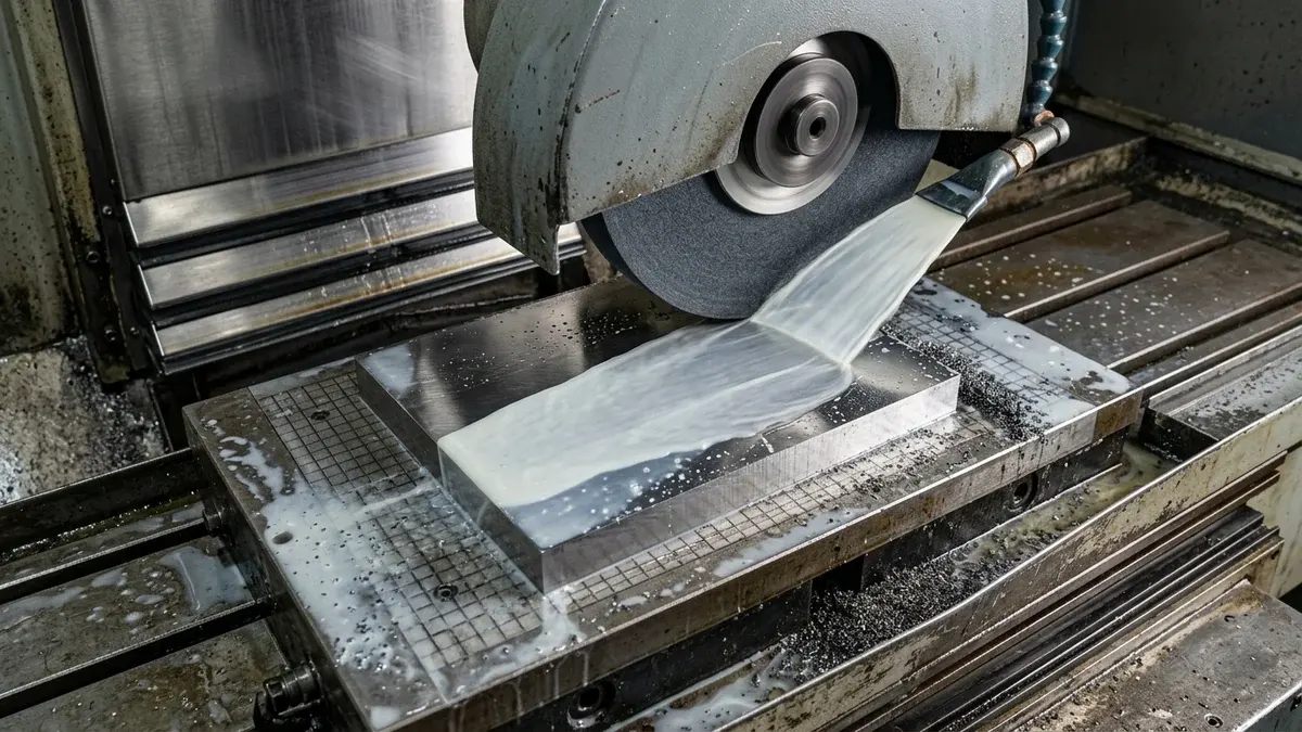
Even with advanced vacuum furnaces and stepped martempering, steel components undergo micro-scale volumetric expansion and relaxation warping. Precision surface and cylindrical grinding serves as the primary subtractive process to bring hardened parts into tight ±0.005 mm (±0.0002″) tolerances:
- Electromagnetic Surface Grinding: Flat plates, die blocks, and guide ways are magnetically clamped onto rectangular electromagnetic chucks. Premium vitrified white aluminum oxide (WA) or ceramic grain grinding wheels take incremental finish passes (0.003 mm to 0.008 mm depth of cut) under heavy flood synthetic cooling. This continuous cooling flushes abrasive swarf and prevents localized surface re-tempering (grinding burn) which could compromise surface fatigue life.
- Stress Redistribution During Clamping: Because a magnetic chuck pulls a warped plate flat during grinding, turning off the chuck magnet can cause the part to spring back into a bowed profile. Our grinding technicians flip and shim the workpiece multiple times, balancing stock removal across opposing datum faces until residual flatness is achieved within a 0.005 mm flatness zone.
8. Shaft & Rotational Symmetry Distortion Control
Long cylindrical shafts and splined power-transmission axles are particularly susceptible to longitudinal bowing and radial out-of-roundness during liquid quenching:
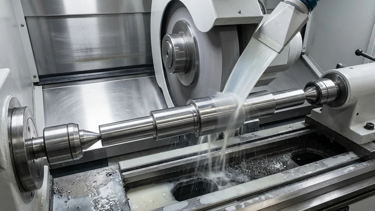
- Between-Centers Cylindrical Grinding: Hardened stepped shafts are fixtured between dead centers on CNC cylindrical OD grinding machines. Utilizing precision carbide-tipped 60-degree centers and steady rests for aspect ratios exceeding length-to-diameter ratio L/D > 8, grinding wheels restore concentricity and runout within ±0.005 mm (±0.0002″).
- Center Hole Conditioning: The high temperatures of austenitizing oxidize and distort the conical 60-degree center holes drilled during rough turning. Prior to OD grinding, technicians perform precision center-hole lapping to establish flawless rotational datum axes.
- In-Process Dimensional Gauging: Digital Marposs-style in-process touch probes continuously monitor workpiece diameter during finish spark-out passes, automatically compensating for grinding wheel wear and thermal expansion of the machine casting.
9. Zero-Cutting-Force EDM for High-Hardness Geometries
When engineering drawings specify deep narrow slots, sharp internal corners, or intricate gear teeth in steels hardened above 60 HRC, mechanical milling tools experience extreme cutting tool deflection and premature edge breakdown. Non-contact electrical discharge machining provides an optimal solution:
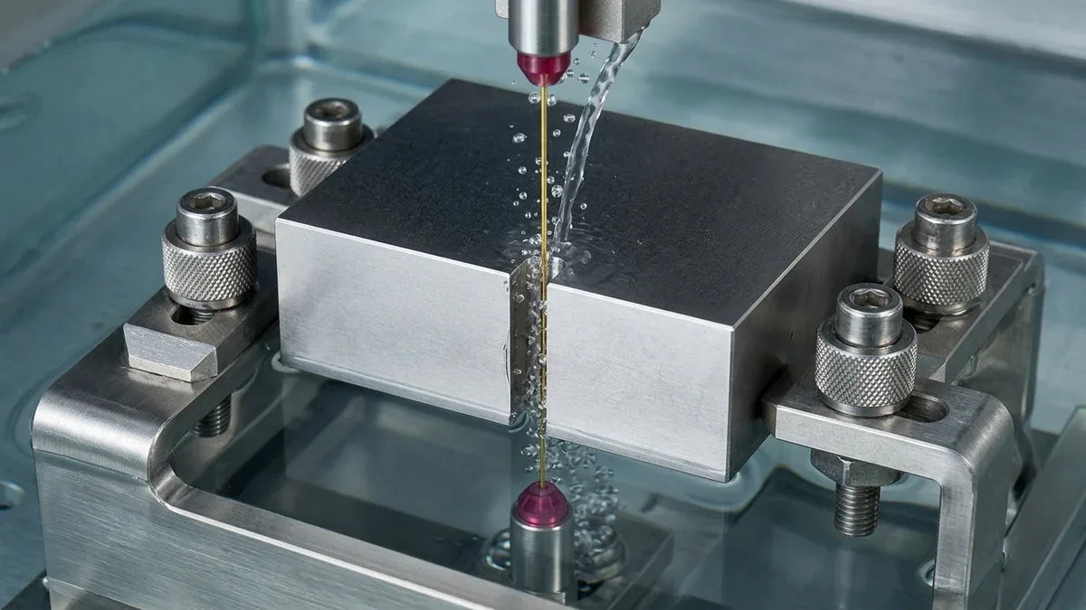
- Submerged Wire EDM: Submerged wire electrical discharge machining (EDM) uses a continuously spooling brass wire (0.20 mm to 0.25 mm diameter) in a deionized dielectric water bath. Because electrical spark erosion exerts zero mechanical cutting force on the workpiece, thin-walled ribs, keyways, and miniature apertures can be machined into hardened tool steels without inducing plastic deformation or deflection.
- Recast Layer (White Layer) Mitigation: Single-pass wire cutting leaves an altered recast layer (10 μm to 20 μm thick) that is hyper-quenched and contains tensile micro-cracks. To protect fatigue-critical prototype assemblies, multi-pass skim cutting (one roughing pass followed by 3 to 4 micro-energy trim passes) strips away the recast layer, achieving an SPI A-2 / Ra 0.2 μm surface roughness with compressive surface stresses.
10. Quality Control, Hardness Verification & Metrology Standards
Rigorous verification ensures heat-treated components satisfy engineering drawing callouts before ex-factory release:
- Rockwell C Hardness Testing (ASTM E18): Direct indentation testing verifies bulk hardness across through-hardened steels (typically 28 to 64 HRC). Technicians calibrate machines against verified diamond spheroconical indenters and calibrated reference test blocks.
- Micro-Vickers Hardness Profiling (ASTM E384): To evaluate shallow case-hardened depths on nitrided or carbonitrided parts, cross-sectional metallographic mounts are polished to a mirror finish. A diamond pyramid indenter applies light loads (HV0.1 to HV1.0) along a calibrated linear traverse, generating a precise hardness-versus-depth curve to identify the effective case depth (ECD) boundary at 50 HRC equivalent.
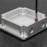
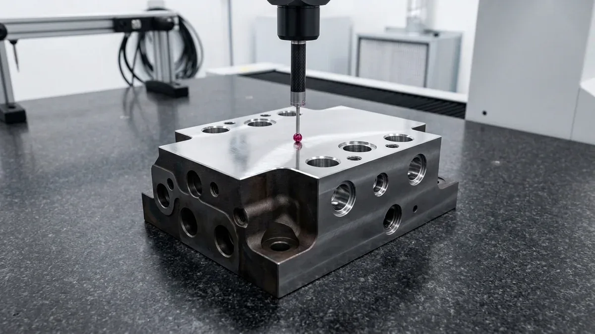
- Zeiss CMM GD&T Metrology: Tactile scanning probes in our climate-controlled inspection lab verify geometric dimensioning and tolerancing (GD&T) callouts including flatness, cylindricity, perpendicularity, and true position across heat-treated datums, with full dimensional inspection reports available upon request.
11. Heat Treatment & Machining Matrix for Common Engineering Alloys
The following engineering guide summarizes standardized thermal cycles, target hardnesses, and practical machining guidelines across key industrial materials:
| Alloy Grade | Material Category | Primary Thermal Process | Target Hardness | Tolerance Capability | Key Machining & DFM Recommendation |
|---|---|---|---|---|---|
| AISI 4140 / 42CrMo4 | Medium Carbon Alloy Steel | Quench & Temper (845°C → Oil → 560°C) | 28 – 34 HRC | ±0.010 mm (Milling) ±0.005 mm (Grinding) | Often pre-hardened (HT condition). Highly machinable; ideal for heavy-duty transmission shafts and fixtures. |
| AISI D2 / SKD11 | High-Carbon High-Chromium Cold Work | Vacuum Austenitize (1020°C) + Gas Quench + Double Temper | 58 – 62 HRC | ±0.005 mm (Grinding) ±0.005 mm (Wire EDM) | High abrasive wear resistance. Machine soft with 0.3 mm grind stock; finish with cBN hard milling or wire EDM. |
| AISI S136 / Stavax ESR | Martensitic Stainless Mold Steel | Vacuum Hardening (1030°C) + Deep Freeze (-80°C) + Temper | 48 – 52 HRC | ±0.010 mm (Hard Milling) SPI A-1 Optical Finish | Sub-zero treatment eliminates retained austenite. Allows diamond polishing for optical lens mold cores. |
| 17-4PH / AISI 630 | Precipitation Hardening Stainless | Condition H900 (480°C × 1h Air Cool) | 40 – 45 HRC | ±0.010 mm (As-Milled) | Machine in Condition A; low aging temperature results in negligible volumetric shrinkage (<0.05%). |
| Aluminum 6061-T6 | Wrought Magnesium-Silicon Aluminum | Solution Treat (530°C) + Water Quench + Artificial Age (160°C) | 95 – 100 HBW (~60 HRB) | ±0.015 mm (Milling) | General structural prototyping alloy. Excellent anodizing response and high machining feed rates. |
| Aluminum 7075-T651 | Zinc-Hardened Aerospace Aluminum | Solution Treat + 1-3% Stretch + Artificial Aging | 150 – 160 HBW (~88 HRB) | ±0.010 mm (Milling) | 500+ MPa yield strength. The T651 stretching process eliminates residual stress, preventing thin-wall warping. |
| Ti-6Al-4V (Grade 5) | Alpha-Beta Titanium Alloy | Solution Treat & Age (STA: 950°C → Water → 540°C) | 36 – 42 HRC | ±0.010 mm (Milling) | High strength-to-weight ratio. Low thermal conductivity requires high-pressure coolant and sharp positive rake tooling. |
12. DFM Rules: Engineering CAD Models to Prevent Thermal Distortion
Achieving tight tolerances on heat-treated parts requires integrating manufacturing realities directly into CAD geometry prior to machining:
- Design Symmetrical Cross-Sections: Abrupt transitions between thick bosses and thin webs create differential cooling rates during quenching, warping the component. Maintain uniform nominal wall thicknesses and incorporate gradual taper transitions (minimum 3:1 ramp slope).
- Generous Internal Corner Fillets: Sharp 90-degree internal corners act as severe thermal stress risers, frequently initiating spontaneous quench cracks during liquid immersion. Specify internal corner radii of at least R ≥ 1.5 mm, or design circular stress-relief undercuts.
- Balance Stock Removal Across Opposing Faces: When milling raw billet stock, alternate roughing passes evenly between top and bottom faces. Asymmetrical material removal unbalances the billet’s internal residual stresses, producing curvature even before the part enters the heat treatment furnace.
- Two-Stage Machining Allowance Strategy:
- Rough Machining Stage: Remove bulk material leaving 0.3 mm to 0.5 mm of excess stock on functional datum faces and critical bores.
- Thermal Processing Stage: Execute stress relief annealing, vacuum hardening, sub-zero cryogenic stabilization, and multi-stage tempering.
- Finish Machining Stage: Utilize precision surface grinding, cylindrical OD grinding, or wire EDM to eliminate thermal movement and achieve final drawing tolerances down to ±0.005 mm (hard milling typically holds ±0.010 mm).
- Blind Hole and Thread Relief: Avoid blind tapped holes with sharp bottoms. Extend thread reliefs and drill depths to prevent quench-oil entrapment and localized steam pocket formation, which can cause soft spots and localized stress cracking.
13. Technical Engineering FAQ
Distortion is primarily driven by two factors: non-uniform thermal contraction during rapid quenching and the volumetric phase transformation from face-centered cubic (FCC) austenite to body-centered tetragonal (BCT) martensite, which causes an approximate 4% volumetric expansion. Asymmetrical part geometry, abrupt cross-sectional transitions, and pre-existing machining stresses compound this movement. Utilizing vacuum gas quenching, symmetrical DFM practices, and pre-hardening stress relief annealing effectively controls this distortion.
Through-hardening heats and quenches the entire cross-section of medium-to-high carbon steel, creating uniform hardness and strength throughout the part, but with lower overall fracture toughness. Case hardening (such as carburizing, carbonitriding, or plasma nitriding) enriches the outer surface layer with carbon or nitrogen, producing an ultra-hard, wear-resistant outer shell (58 to 70 HRC) while preserving a ductile, impact-absorbing core.
Conventional quenching to ambient room temperature often leaves between 5% and 18% unstable retained austenite in high-alloy tool steels like D2 and S136. Sub-zero cryogenic treatment forces the microstructural transformation of retained austenite into stable martensite, eliminating long-term dimensional growth and post-assembly distortion while precipitating fine eta-carbides that enhance abrasive wear life.
Yes, but tolerances of ±0.005 mm cannot be held solely through pre-hardening milling. The optimal production sequence requires rough CNC machining with 0.3 mm to 0.5 mm stock allowance, followed by vacuum heat treatment and cryogenic stabilization, and concluding with finish surface grinding, cylindrical OD grinding, hard milling, or submerged wire EDM to achieve final drawing tolerances.
Partner with Our Precision CNC Machining & Engineering Team
Eliminate tool deflection, residual stress distortion, and tolerance stack-up risks before production begins. Upload your 3D CAD files (STEP/IGES) and 2D GD&T drawings for a comprehensive shop-floor DFM review and custom quotation.
Upload 3D CAD for Engineering DFM & RFQ