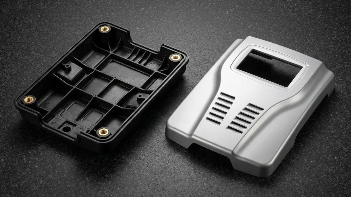
Designing large structural polymer enclosures—such as medical diagnostic gantry covers, autonomous mobile robot (AMR) cowlings, and heavy equipment fascias—creates a severe tooling dilemma. High-pressure thermoplastic injection molding demands massive hardened steel molds and multi-thousand-ton hydraulic presses, imposing prohibitive tooling investment when annual demand sits between 50 and 5,000 units.
Reaction Injection Molding resolves this low-to-mid-volume bottleneck by replacing high-viscosity molten thermoplastics with low-viscosity reactive liquid monomers. By impinging liquid isocyanate and polyol streams at 10 to 20 MPa (1,450 to 2,900 PSI) before laminar cavity filling at 0.3 to 0.8 MPa (45 to 115 PSI), thermoset polyurethane cures inside 6061-T6 aluminum molds without sink marks.
At our in-house facility, our polymer engineering and CNC toolmaking teams execute turn-key Reaction Injection Molding alongside custom rapid injection molding services and low-volume polyurethane vacuum casting. This guide covers impingement mixing physics, polyurethane foam formulations, billet aluminum tooling, clamping tonnage calculations, and shop-floor DFM rules.
Executive Summary & Engineering Takeaways (BLUF)
- Two-Stage Pressure Physics: Isocyanate and polyol streams collide at 10 to 20 MPa (1,450 to 2,900 PSI, typical 15 MPa / 2,175 PSI) inside a self-cleaning mixhead, then cure inside a 50 to 70 °C (122 to 158 °F) mold at 0.3 to 0.8 MPa (45 to 115 PSI)—reducing clamping tonnage by over 95% (99.3%).
- Four RIM PU Chemistries: Specify Rigid Solid PU (1.05–1.20 g/cm³, Shore 75D–85D, 2.5–10.0 mm walls, HDT 85 °C), Integral-Skin Structural Foam PU (0.50–0.85 g/cm³, 4.0–25.0 mm zero-sink walls), Elastomeric PU (Shore 55A–65D), or Glass-Reinforced RRIM.
- Scalable Tooling Tiers: Choose cast epoxy molds (20–100 shots), High-Speed 3-Axis/4-Axis CNC-machined 6061-T6 (100–3,000+ shots) or 7075-T651 (~150 HB, 500–5,000+ shots) billet aluminum molds, or P20/718H (28–34 HRC), NAK80 (37–42 HRC), and H13/S136 (48–52 HRC) steel molds (3,000–10,000+ shots).
- Tolerances & DFM: Molded polyurethane holds ±0.20% to ±0.30% linear tolerances (minimum ±0.25 mm), while CNC-machined mold locating pins achieve ±0.010 to ±0.020 mm (±0.0004″ to ±0.0008″) with general machined geometry governed by ISO 2768-mK.
- Ex-Factory Turnaround: DFM quotes within 24 hours, CNC aluminum tooling and T1 samples in 18 to 35 business days, 2K PU painted/EMI-shielded short-run batches in 7 to 12 business days, and low-to-mid-volume production in 7 to 30 business days (separate from 3 to 5 business days air transit).
Article Engineering Navigation
- 1. How Does High-Pressure Impingement Mixing Enable Low-Pressure RIM Curing?
- 2. RIM Polyurethane Chemistries: Solid, Structural Foam, Elastomeric & RRIM
- 3. Low-Pressure RIM Tooling Architectures & Process Comparison
- 4. Why Does Reaction Injection Molding Cut Clamping Tonnage by 99%? (Physics & DFM)
- 5. Shop-Floor Troubleshooting, Limitations & Surface Finishing
- 6. In-House Ex-Factory Lead Times & Selection Guide
- 7. Technical Engineering FAQ
1. How Does High-Pressure Impingement Mixing Enable Low-Pressure RIM Curing?
Unlike thermoplastic injection molding—which melts solid polymer pellets at 220 to 300 °C and injects high-viscosity melt under extreme hydraulic pressure—Reaction Injection Molding is a chemical thermosetting process. Two low-viscosity liquids, Component A (polymeric MDI isocyanate) and Component B (polyol blend with catalysts), are conditioned in day tanks at 25 to 35 °C (77 to 95 °F).
Inside temperature-jacketed day tanks blanketed with dry nitrogen, Component A and Component B maintain dynamic viscosities between 100 and 500 mPa·s (0.10 to 0.50 Pa·s). Axial metering pumps regulate the isocyanate-to-polyol stoichiometric index (NCO/OH molar ratio) between 1.02 and 1.08 with ±0.5% closed-loop mass-flow accuracy to guarantee complete cross-linking.
During each shot, axial piston pumps pressurize both streams to 10 to 20 MPa (1,450 to 2,900 PSI, typical 15 MPa / 2,175 PSI) through hardened carbide orifices (⌀1.2 to 2.5 mm). Opposing jets collide at 100 to 150 m/s inside the mixhead chamber, exceeding the critical Reynolds number (Re = ρ·v·d/μ > 300–500, typically Re ≈ 660).
After intense turbulent micro-mixing, the reacting liquid exits through a pressure-drop aftermixer and wide laminar fan gate into a 50 to 70 °C (122 to 158 °F) mold cavity at 0.3 to 0.8 MPa (45 to 115 PSI, typical 0.5 MPa / 72.5 PSI), curing exothermically within 90 to 240 seconds (see schematic below).
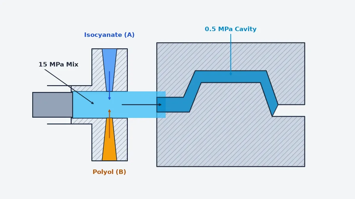
- Monomer Conditioning & Metering: Isocyanate (Component A) and polyol (Component B) are thermally stabilized at 25 to 35 °C under dry nitrogen blanketing and metered by axial piston pumps to ±0.5% stoichiometric ratio accuracy.
- High-Pressure Impingement Mixing: Opposing monomer jets collide at 10 to 20 MPa (1,450 to 2,900 PSI, Re ≈ 660) inside the L-style mixhead chamber before a close-tolerance hydraulic piston purges residual material without solvent flushing.
- Laminar Fan-Gate Injection & Cure: Pressure drops across the aftermixer and wide laminar fan gate, filling the 50 to 70 °C aluminum mold at 0.3 to 0.8 MPa (45 to 115 PSI) to prevent air entrapment during the 90 to 240-second cure.
- Demolding, Post-Cure & Finishing: The cross-linked polyurethane enclosure is demolded, thermally stabilized at 65 °C when required, routed on 3-axis CNC fixtures, and finished with 2K polyurethane paint or internal EMI shielding.
2. RIM Polyurethane Chemistries: Solid, Structural Foam, Elastomeric & RRIM
By adjusting isocyanate stoichiometry, foaming additives, and glass fibers, our shop processes four primary RIM polyurethane families. Rigid Solid PU cures without foaming additives into a dense 1.05 to 1.20 g/cm³ cross-section (Shore 75D to 85D, flexural modulus 1,800 to 2,400 MPa) with an 85 °C heat deflection temperature across 2.5 to 10.0 mm walls.
Integral-Skin Structural Foam PU uses chemical foaming additives to generate a micro-cellular core (0.50 to 0.85 g/cm³ overall density) inside a dense 1.0 to 2.0 mm outer skin condensed against the 55 °C mold face. Internal foaming pressure packs the skin outward, enabling 4.0 to 25.0 mm walls and bosses with zero sink marks (see cutaway below).
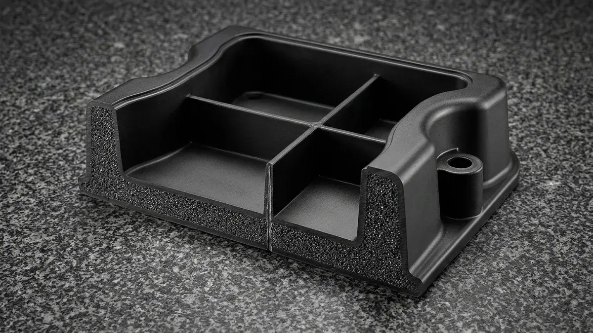
While the 50 to 60 °C aluminum mold quenches the outer boundary into a solid 1.05 to 1.15 g/cm³ skin, the core reaches 110 to 135 °C exothermically. By cube-law rigidity (D ∝ E·h³), an 8.0 mm foam wall versus a 4.0 mm solid wall ((8/4)³ = 8×) yields a 4.8× specific stiffness gain at 0.60× modulus.
For impact-absorbing guards, Elastomeric PU (Shore 55A to 65D) delivers 150% to 350% elongation at break and cold-impact resilience down to -40 °C. Conversely, Glass-Reinforced RRIM suspends 15% to 25% milled glass fibers (0.15 to 0.40 mm) in the polyol stream, raising flexural modulus to 2,800 to 3,200 MPa and lowering CTE to 30 to 45 × 10-6 /K.
| RIM PU Chemistry | Density (g/cm³) | Hardness & Modulus | Wall Range (mm) | Thermal / CTE Spec | Recommended Application / When to Choose |
|---|---|---|---|---|---|
| Rigid Solid PU | 1.05–1.20 g/cm³ | Shore 75D–85D | 1,800–2,400 MPa | 2.5–10.0 mm | HDT 85 °C | CTE 90–110 × 10-6 /K | Medical imaging consoles, diagnostic bezels, structural instrument cabinets. |
| Integral-Skin Structural Foam PU | 0.50–0.85 g/cm³ | Skin 65D–80D | 1,100–1,600 MPa | 4.0–25.0 mm (Zero sink) | HDT 80 °C | Cellular Thermal Barrier | Large weight-sensitive doors, thick-boss covers, acoustic shrouds. |
| Elastomeric PU | 1.00–1.15 g/cm³ | Shore 55A–65D | 150%–350% Elong. | 2.5–8.0 mm | -40 °C to +80 °C Impact Resilience | AMR collision bumpers, off-highway fenders, shock-absorbing boots. |
| Glass-Reinforced RRIM | 1.25–1.45 g/cm³ | Shore 75D–85D | 2,800–3,200 MPa | 2.5–8.0 mm | CTE 30–45 × 10-6 /K | Exterior automotive body panels and guards needing low thermal expansion. |
3. Low-Pressure RIM Tooling Architectures & Process Comparison
Because RIM curing pressures stay within 0.3 to 0.8 MPa at 50 to 70 °C, toolmakers avoid the massive tonnage required for 60 to 120 MPa thermoplastic injection. Cast epoxy tools serve 20 to 100 prototype shots, while P20/718H (28–34 HRC), NAK80 (37–42 HRC), and H13/S136 hardened steel (48–52 HRC) molds support 3,000 to 10,000+ shots.
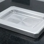
For 100 to 3,000+ shots, wrought billet aluminum is the workhorse. Using high-speed 3-axis and 4-axis CNC machining centers, we rough and stress-relieve 6061-T6 blocks at 150 to 165 °C (holding 7075-T651 at ~150 HB strictly ≤100 to 110 °C to prevent over-aging above 120 °C) before finishing the mixhead pocket, laminar fan gate, and outer O-ring groove (below).
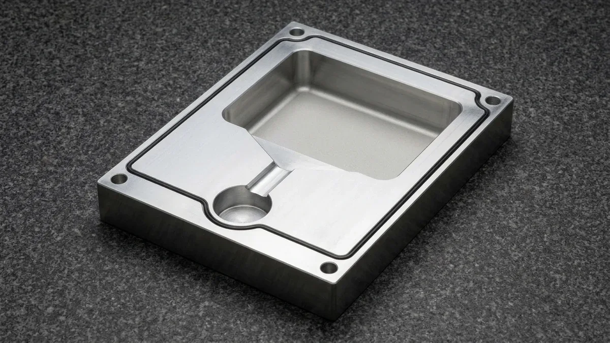
Wrought 6061-T6 aluminum provides a thermal conductivity of 167 W/(m·K)—nearly five times higher than P20 mold steel at 34 W/(m·K). By gun-drilling ⌀10 to ⌀12 mm water channels 20 mm beneath the cavity face, our aluminum molds dissipate exothermic polymerization heat (80 to 110 kJ/kg) uniformly, holding surface temperatures within ±1.5 °C.
Unlike high-tonnage injection presses, RIM molds mount inside pneumatic or hydraulic book-style mold carriers featuring 0° to 45° dual-axis tilt tables. A continuous 4.0 to 6.0 mm outer perimeter EPDM or silicone O-ring seal compressed along the parting line encircles both the mixhead chamber and cavity, preventing monomer flash without crossing the runner.
| Process | Tooling & Life (Shots) | Cavity Pressure | Wall & Boss Design | Tooling Investment | Recommended Application / When to Choose |
|---|---|---|---|---|---|
| Reaction Injection Molding (RIM) | Epoxy (20–100) | 6061-T6 (100–3,000+) & 7075-T651 (~150 HB, 500–5,000+) Al | P20 / 718H (28–34 HRC), NAK80 (37–42 HRC) & H13 / S136 (48–52 HRC) Steel (3,000–10,000+) | 0.3–0.8 MPa (45–115 PSI) | 2.5–25.0 mm variable walls, bosses, inserts, zero sink | Low-to-Moderate CNC Aluminum NRE | 50–5,000/yr large medical, robotics, and industrial enclosures. |
| Thermoplastic Injection | 7075 Al (500–5,000) | P20 (28–34 HRC) / S136 (48–52 HRC) Steel (50,000–500,000+) | 60–120 MPa (8,700–17,400 PSI) | 1.5–4.0 mm uniform walls; ribs ≤60% wall thickness | High Hard-Tooling Investment | 5,000–500,000+ units/yr with fast 30-second cycle times. |
| PU Vacuum Casting | RTV Silicone Mold over SLA Master (15–25 shots) | ~0.1 MPa Vacuum Differential | 1.5–12.0 mm; fine textures and minor undercuts | Minimal Soft-Tooling Setup | 10–50 validation prototypes prior to cutting aluminum RIM molds. |
| Heavy-Gauge Thermoforming | Single-Sided Aluminum Form Tool (1,000–10,000+ shots) | 0.1–0.5 MPa Vacuum Assist | 2.0–10.0 mm sheet; corner thinning, no B-side bosses | Low Single-Sided Mold NRE | Simple shell covers without integrated B-side bosses or ribs. |
4. Why Does Reaction Injection Molding Cut Clamping Tonnage by 99%? (Physics & DFM)
To understand why Reaction Injection Molding dominates large polymer enclosures (up to 2,000 mm × 1,200 mm), engineers must examine the hydraulic clamping force equation governing mold separation. In any closed-mold process, press clamping force must exceed projected cavity area multiplied by peak internal cavity pressure.
📐 Shop-Floor Engineering Calculation: Mold Clamping Force & Impingement Physics
Governing Equations: Clamping Force Fclamp = Aproj × Pcav (where 1 metric ton-force tf = 9.80665 kN, 1 US ton-force = 8.896443 kN) and Impingement Reynolds Number Re = (ρ · v · d) / μ > 300–500.
1. Impingement Mixing Reynolds Verification: For polyol (ρ = 1,100 kg/m³, v = 120 m/s, d = 0.002 m, μ = 0.40 Pa·s), Re = (1,100 × 120 × 0.002) ÷ 0.40 = 660; for isocyanate (1,220 × 130 × 0.002 ÷ 0.48 = 660.8; or 1,050 × 140 × 0.0018 ÷ 0.40 = 661.5), exceeding Recrit = 300–500.
2. Large Fascia Clamping Comparison (Aproj = 0.64 m²):
• High-Pressure Thermoplastic Injection (100 MPa): Fclamp = 0.64 × 100,000 = 64,000 kN (6,526.2 tf ≈ 6,526 tf / 7,194 US tons).
• Reaction Injection Molding (0.70 MPa): Fclamp = 0.64 × 700 = 448 kN (45.7 tf / 50.4 US tons) — a 99.3% tonnage reduction.
3. Mid-Size Enclosure Benchmark (800×500 mm, Aproj = 0.40 m²): At typical 0.5 MPa RIM vs. 70 MPa thermoplastic injection, clamping drops from 28,000 kN (2,855.2 tf) to 200 kN (20.4 tf) (99.3% reduction; or on 800×600 mm / 4,800 cm² ≈ 744 in² at 1.0 MPa vs. 35 MPa, from 16,800 kN / 1,713 tf to 480 kN / 48.9 tf, 97.1%).
4. Exothermic Heat & 6061-T6 Mold Thermal Expansion: A 2.5 kg PU shot (ΔH = 100 kJ/kg) releases Q = 250 kJ (2.08 kW over 120 s). Heating a 1,000 mm 6061-T6 mold (α = 23.1 × 10⁻⁶ /K) from 20 °C to 60 °C (ΔT = 40 K) expands cavity length by ΔL = +0.924 mm (+0.092%).
Neat elastomeric and unfilled rigid or structural foam polyurethanes shrink 0.6% to 1.2% during curing, while glass-reinforced RRIM shrinks 0.4% to 0.8% (0.15%–0.35% along fiber flow). By scaling 6061-T6 cavity CAD geometry, we hold ±0.20% to ±0.30% linear tolerances (minimum ±0.25 mm), with CNC locating pin bores at ±0.010 to ±0.020 mm per ISO 2768-mK.
For clean demolding, apply four core RIM DFM rules: specify 1.5°–3.0° draft on smooth walls and 3.0°–5.0° on textured surfaces; blend 2.5–25.0 mm wall transitions with 3.0–6.0 mm fillets; pre-load knurled C3604 brass threaded inserts (M3–M10) onto locating pins; and tilt parting lines 15°–45° toward high-point 0.05–0.10 mm vents.
| DFM Feature | Solid / RRIM PU Spec | Structural Foam PU Spec | Tooling / Tolerance Rule | Recommended Application / When to Choose |
|---|---|---|---|---|
| Nominal Wall Thickness | 2.5–10.0 mm | 4.0–25.0 mm variable walls | R 3.0–6.0 mm transition fillets | Thick-to-thin load-bearing flanges and diagnostic doors. |
| Draft Angle & Texture | 1.5°–3.0° smooth | 3.0°–5.0° textured | 2.0°–3.5° smooth | 3.5°–5.0° textured | Add +1.0° per 0.025 mm texture depth | Deep vertical side walls requiring drag-free release. |
| Ribs & Molded-In Inserts | Ribs 0.50T–0.65T; Boss OD 2.2× insert | Ribs 0.75T–1.00T (zero sink marks) | Locating pins ±0.010 to ±0.020 mm | Encapsulated C3604 brass M3–M10 chassis mounting points. |
| Linear & Post-CNC Tolerances | ±0.15%–±0.25% (RRIM) | ±0.20%–±0.30% | ±0.25%–±0.35% (min ±0.25 mm) | Post-CNC bores ±0.020 to ±0.050 mm; ISO 2768-mK | Precision bearing seats, display cutouts, and mating bezels. |
5. Shop-Floor Troubleshooting, Limitations & Surface Finishing
In a T1 trial of a 1,100 mm × 650 mm structural foam medical cover (Symptom), 0.3 to 0.8 mm subsurface micro-bubbles appeared along an upper louver bezel and blistered during 65 °C paint baking. Inspection revealed (Root Cause) a flat mold orientation trapping air behind the louver core alongside >0.08% moisture in the polyol day tank.
To eliminate the defect (Corrective Action), our tooling engineers tilted the 6061-T6 mold by 28° on the press carrier for upward gravity displacement, milled three 0.08 mm × 15 mm high-point vents, blanketed the polyol tank with dry nitrogen, and added a 65 °C × 2-hour post-mold outgassing bake prior to priming.
Because external wax or silicone mold release agents contaminate raw polyurethane skins, painting without multi-stage pretreatment causes fisheyes and delamination. Our finishing line executes 55 °C alkaline aqueous washing, isopropyl alcohol (IPA) degreasing, and 180-grit scuff sanding before spraying conductive 2K urethane primer, achieving ASTM D3359 5B cross-hatch paint adhesion.
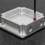
In our 20 °C ± 1 °C metrology lab, Optical Emission Spectroscopy (OES) verifies incoming mold alloys, while Zeiss Bridge CMM probing is restricted to CNC-machined aluminum and steel mold cavities. Polyurethane RIM parts are verified via non-contact 2.5D Optical VMS, Class ZZ GO/NO-GO pin gauges, Archimedes density balances, and Shore D/A durometers (ASTM D2240 / ISO 868).
When NOT to Choose RIM: Avoid RIM above 10,000 units/year (where 3–6 minute cure cycles lose to 30-second thermoplastic molding), when parts require unpainted UV stability, or below 2.5 mm wall thickness. In our in-house surface finishing department, demolded housings undergo degreasing, 2K urethane priming, automotive 2K polyurethane painting, and internal copper/nickel EMI shielding spray (35–65 dB attenuation).
6. In-House Ex-Factory Lead Times & Selection Guide
Our in-house facility integrates 3-axis and 4-axis CNC aluminum mold making, impingement molding, CNC trimming fixtures, and 2K paint booths. All schedules below represent Ex-Factory Production & Inspection Turnaround (including our 3-business-day inspection and paint-curing buffer), separate from 3 to 5 business days air transit (DHL/FedEx/UPS):
- DFM Review & Quotation: Within 24 hours (24 to 48 hours for multi-part enclosure assemblies and tooling packages).
- Unpainted Rapid Master Models & Simple Trim Fixtures: 4 to 8 business days Ex-Factory.
- Surface-Finished RIM Prototypes & Short-Run Batches (2K PU Painted / Silk-Screened / EMI Shielded): 7 to 12 business days Ex-Factory.
- CNC-Machined 6061-T6 / 7075-T651 Aluminum RIM Mold & T1 Samples: 18 to 35 business days Ex-Factory.
- Low-to-Mid Volume RIM Production (10 to 1,000+ Units): 7 to 30 business days Ex-Factory.
- Selection Rule: Choose Vacuum Casting for 5–50 prototypes; Sheet Metal for bent flat enclosures; Reaction Injection Molding for 50–5,000/yr large contoured housings (2.5–25.0 mm walls); and Thermoplastic Injection Molding above 5,000–10,000+ units/yr.
For hardware teams scaling from clinical or field trials into commercial production, combining RTV silicone vacuum casting (10 to 50 units) with CNC-machined 6061-T6 aluminum RIM tooling (100 to 3,000+ units) eliminates six-figure steel mold amortization while preserving full freedom to iterate industrial design between production batches.
🔗 Related Polymer & Tooling Engineering Guides
- Design for Manufacturing (DFM) Engineering Review Services — See how our tooling engineers optimize draft angles, parting lines, and wall transitions before cutting mold metal.
- Aluminum Injection Mold vs. Steel Tooling Engineering Guide — Compare CNC-machined 6061-T6 and 7075-T651 aluminum bridge tooling against P20 and H13 steel molds across lifecycle volumes.
- Polyurethane Vacuum Casting & Urethane Molding Guide — Evaluate RTV silicone mold casting for 10 to 50 validation enclosures prior to investing in aluminum RIM tooling.
7. Technical Engineering FAQ
As-molded Reaction Injection Molding polyurethane parts hold linear tolerances of ±0.20% to ±0.30% of nominal length (minimum ±0.25 mm). For critical mating bores requiring ±0.020 mm to ±0.050 mm precision, we post-machine features on CNC routing fixtures with mold datums held to ISO 2768-mK.
In structural foam RIM, chemical foaming additives generate 0.3 to 0.8 MPa internal pressure while a dense 1.0 to 2.0 mm skin condenses against the 50 to 70 °C aluminum mold. This cellular expansion packs the skin across 4.0 to 25.0 mm walls without sink marks.
Because RIM operates at 0.3 to 0.8 MPa (45 to 115 PSI) and 50 to 70 °C, a CNC-machined 6061-T6 or 7075-T651 billet aluminum mold produces 100 to 3,000+ shots. For 3,000 to 10,000+ shots or abrasive glass-reinforced RRIM, we utilize P20 or 718H steel molds.
Yes, low-pressure laminar filling allows knurled C3604 brass threaded inserts to be pre-loaded onto CNC mold locating pins (±0.010 to ±0.020 mm) for high-torque encapsulation. After demolding and 2K polyurethane painting, we apply internal copper or nickel EMI shielding sprays delivering 35 to 65 dB attenuation.
Ready to Tool Your Large Polyurethane Enclosure with Reaction Injection Molding?
Upload your 3D CAD models (STEP/IGES) and 2D engineering drawings for a comprehensive Reaction Injection Molding DFM review, parting-line and gating analysis, and custom 6061-T6 aluminum tooling quotation from our engineering team.
Upload 3D CAD for DFM & RIM Tooling Quote →