Design for Manufacturing (DFM) Services & CAD Guide: CNC, Sheet Metal, Molding & 3D Printing
3/4/5-Axis CNC Machining Rules
Sheet Metal DIN 6935 Forming Rules
Injection Molding Sink & Draft Control
DfAM Overhang & Hybrid CNC Stock
ASME Y14.5 GD&T Optimization
Empirical production data shows that 70% to 80% of a custom part’s unit cost is locked in during initial Computer-Aided Design (CAD) modeling. Aligning Design for Manufacturing (DFM) and Design for Assembly (DFA) geometry with shop-floor physics eliminates unmachinable corners, sheet metal bend tearing, molding sink marks, and blanket over-tolerancing.
At AS Prototypes, our in-house manufacturing engineering team pairs this cross-process DFM reference with a complimentary 24-hour redline audit on every uploaded STEP, Parasolid, or native 3D CAD assembly—verifying toolpath reach, datum stability, and critical ±0.010 mm (±0.0004″) fit tolerances before cutting metal or mold steel.
1. The 5-Stage Engineering DFM Review Workflow & Tolerance Cost Economics
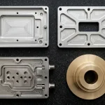
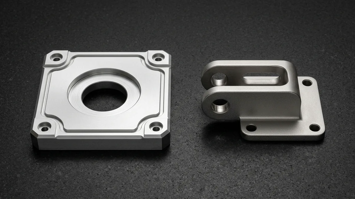
Resolving a geometric oversight follows the manufacturing Rule of Ten: fixing an unmachinable corner or missing draft costs 10× more during prototyping, 100× more after cutting H13 mold steel, and 1,000× more in assembly. Every uploaded CAD package—like the 6061-T6 motor adapter plate and 17-4PH clevis fork shown—undergoes our 5-stage review:
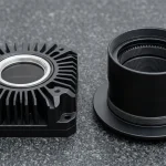
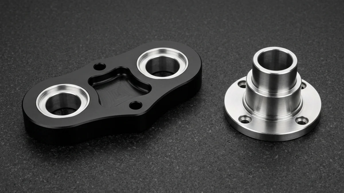
Blanket tight tolerances across non-mating walls inflate machining and inspection time by 2.0× to 5.0×. As shown on the Type III hard-anodized 7075-T651 link plate and cylindrical-ground 17-4PH flanged sleeve below, assign ISO 2768-mK general machining tolerances globally while isolating ±0.010 mm (±0.0004″) reamed or ground fits strictly to functional bearing interfaces:
| Tolerance Precision Tier | Dimensional Threshold | Shop-Floor Machining & Metrology Requirements | Relative Cost Multiplier |
|---|---|---|---|
| Tier 1: Standard Commercial | ISO 2768-mK (±0.1–0.5 mm by size up to 400 mm) | High-efficiency 3/4-axis roughing & standard finishing passes (Ra 1.6–3.2 μm / 63–125 μin); digital caliper and pin gauge checks. | 1.0× (Baseline) |
| Tier 2: Fine Locating Fit | ±0.020 mm to ±0.050 mm (±0.0008″–0.0020″) | Dedicated spring finishing passes (Ra 0.8 μm / 32 μin); spindle thermal warm-up; calibrated outside micrometers and cylindrical plug gauges. | 1.3× to 1.6× |
| Tier 3: High-Precision Fit | ±0.010 mm (±0.0004″) / ISO 286 H7 | Micro-grain carbide boring/reaming (e.g., H7 +0/+0.018 mm on Ø10–18 mm bores); in-situ touch probing; 20°C ± 1°C Zeiss CMM verification. | 2.0× to 2.5× |
| Tier 4: Ground / Wire EDM / Swiss | ±0.005 mm (±0.0002″) | Okamoto/Palmary CNC grinding, Star Swiss micro-turning, or Sodick submerged Wire EDM (1 rough + 3–4 skim cuts, Ra 0.2 μm / 8 μin); 100% CMM QC. | 3.5× to 5.0× |
2. Core DFM Rules for Precision CNC Machining (3/4/5-Axis Milling & Turning)
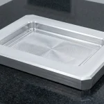
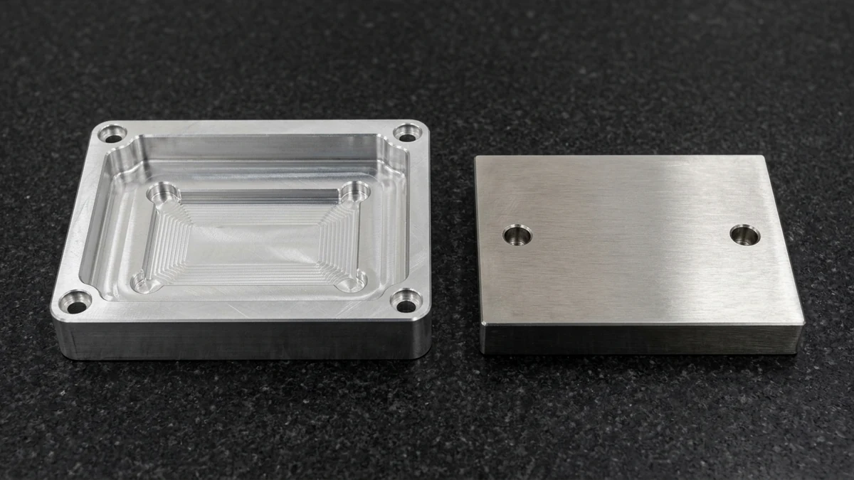
In subtractive Computer Numerical Control (CNC) machining, 3-axis and 4-axis vertical machining centers (VMCs) produce 75%–85% of prismatic parts, while simultaneous 5-axis CNC machining targets impellers and compound manifolds. As seen in the 6061-T6 stepped pocket with circular dog-bone corner reliefs and mating 304 stainless plate below, cutter-friendly radii eliminate Electrical Discharge Machining (EDM):
δ = (F × L³) / (3 × E × I) ⇒ δ ∝ L³ / D⁴Internal Vertical Pocket Radii
Rotating end mills cannot cut a sharp 90° vertical corner without expensive secondary Sinker EDM. Specifying R3.5 mm (0.138″) for a Ø6.0 mm (0.236″) cutter (r = 3.0 mm) lets the tool interpolate a smooth arc without chattering.
Dog-Bone & T-Bone Corner Reliefs
When a rectangular printed circuit board (PCB), battery module, or mating plate must seat 100% flush inside a milled recess, add circular dog-bone relief undercuts slightly past each vertex so standard end mills clear the corners cleanly.
Pocket Depth-to-Diameter Ratio (L/D)
Because cantilever deflection scales with L³/D⁴, deep narrow cavities cause severe acoustic chatter and tapered walls. Step down deep pockets or add 1°–2° sidewall draft so rigid tapered shrink-fit holders reach the floor.
Minimum Wall & Rib Thickness
Thin walls vibrate harmonically under radial cutting pressure and bow elastically after vise release. Maintain ≥1.0 mm (0.039″) walls on 6061/7075 aluminum and ≥1.5 mm (0.059″) on 316L stainless steel, Ti-6Al-4V, PEEK, and POM (acetal).
Blind Tapped Hole Relief
The first 6 threads carry over 85% of axial bolt load. Tapping into the bottom drill cone packs chips and snaps taps; extend pilot holes ≥0.5×D past full threads and size pre-drills separately for cut taps (D − P) vs. form taps (D − 0.5P).
Turning Undercuts & Setup Access
On CNC turned shafts, include R0.4/R0.8 mm shoulder radii and 1.5×pitch thread relief grooves. Consolidate prismatic features into 1–2 vise setups to eliminate datum transfer stack-up.
3. Core DFM Rules for Precision Sheet Metal Fabrication (DIN 6935)
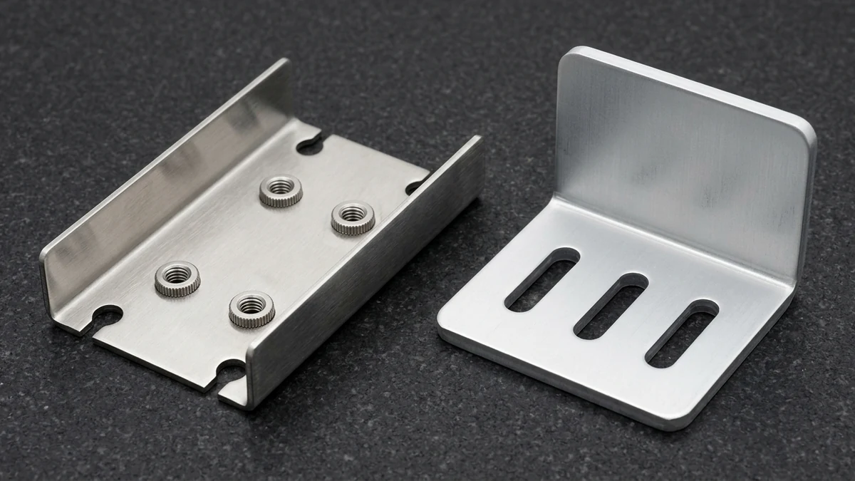
In precision sheet metal fabrication, parts are fiber-laser cut and air-bent on CNC press brakes from a single uniform stock gauge (tinner ≡ touter across 0.5–12.0 mm / 0.020″–0.472″). As demonstrated by the 304 stainless U-channel with tear-drop bend reliefs and knurled clinch nuts beside the slotted 5052-H32 L-bracket below, respecting neutral-axis strain prevents tearing:
BA = (π / 180) × θ × (R_in + K × t) | R_out = R_in + tUniform Gauge & Bend Radius
Keep sheet thickness uniform and standardize on R_in = 1.0×t (5052-H32, 304, SPCC) for single-setup V-die forming. Avoid tight cold bends on 6061-T6 (which fractures below R_in = 3.0–6.0×t); specify 5052-H32 for bent aluminum chassis.
Corner Bend Relief Notches
Where a bent flange meets a flat edge or adjacent flange, add a laser-cut tear-drop or rectangular bend relief notch (minimum 1.5 mm / 0.059″ wide) extending past the bend tangent to prevent corner shear tearing.
Hole-to-Bend Line Setback
Holes and slots placed inside the bending zone stretch into ovals under tensile plastic flow. Keep cutout edges at least 2.5t + R_in clear of the bend tangent so circular knurled clinch nuts seat concentrically.
Min Flange & Clinch Clearance
Short flanges slip into the lower V-die opening (V = 6t–8t) during air bending. Maintain straight flange length ≥ 4t + R_in, and space circular self-clinching fastener centerlines ≥ 1.5× hole diameter from sheet edges.
4. Core DFM Rules for Plastic Injection Molding, Vacuum Casting & 3D Printing
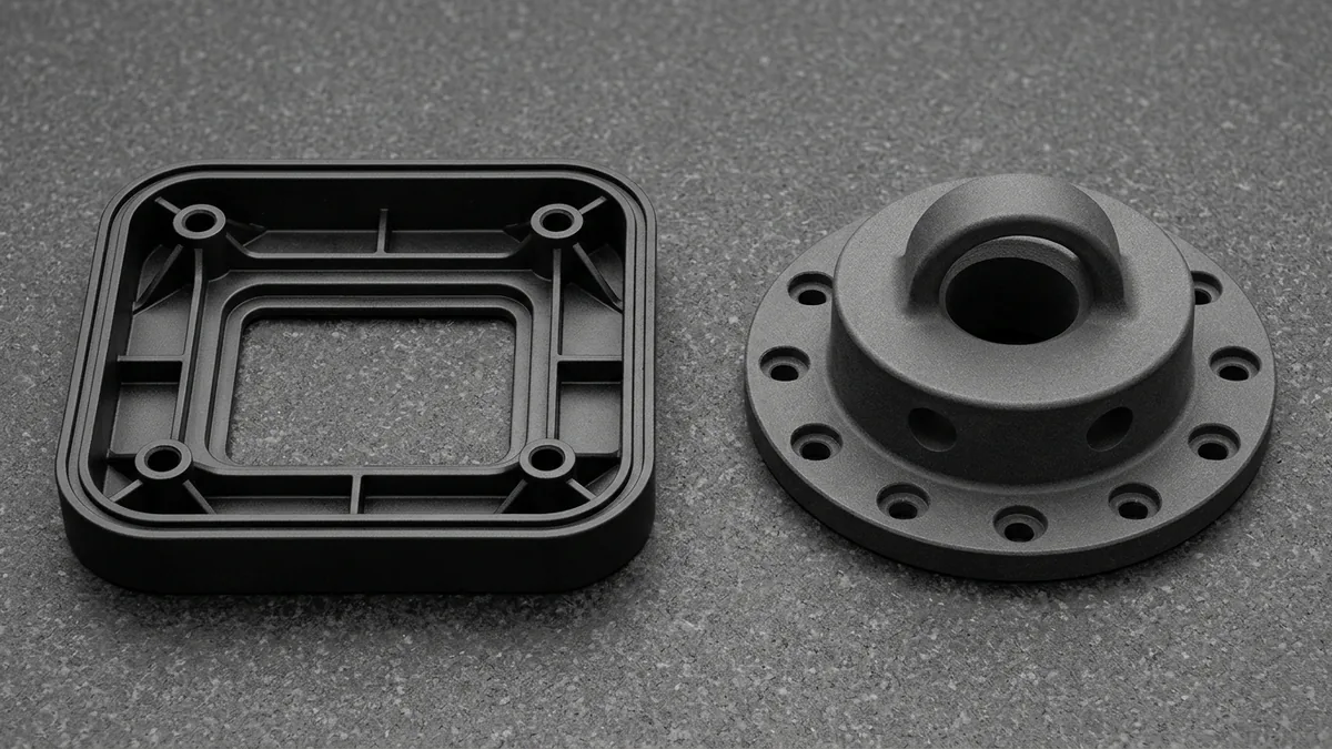
When scaling polymer components across rapid injection molding, polyurethane vacuum casting, and industrial 3D printing, volumetric shrinkage and core ejection friction govern yield. As illustrated by the thin-ribbed PC-ABS frame with gusseted cored bosses and the self-supporting HP Multi Jet Fusion (MJF) PA12 manifold below, uniform coring eliminates sink marks and trapped supports:
Uniform Nominal Wall Thickness
Uneven sections cool at differential rates, causing warpage and vacuum voids. Maintain uniform injection molding wall thickness (±10% consistency) and ramp unavoidable step transitions over a gradual 3:1 taper.
The 50%–60% Rib Thickness Rule
Thick ribs create a heavy molten hot-spot junction at the root that pulls a visible sink shadow on the opposite cosmetic face. Restrict rib base thickness to 50% (POM/PA66) or 60% (ABS/PC) of nominal wall.
Cored Screw Bosses & Gussets
Never design solid plastic bosses. Core out mounting bosses to 60% of the adjacent wall thickness and brace them with triangular gusset ribs to achieve high fastener pull-out torque without exterior sink craters.
Vertical Draft & Texture Allowance
Cooling resins shrink tightly onto mold cores. Apply 0.5°–1.0° base draft on polished walls (1.0°–2.0° standard) plus 1.0°–1.5° per 0.025 mm (0.001″) of VDI 3400 / Mold-Tech texture depth (e.g., 1.5°–2.0° for VDI 24; 2.5°–3.0° for VDI 30).
45° Overhangs & Teardrop Channels
In Direct Metal Laser Sintering (DMLS), circular horizontal channels >Ø8 mm (0.315″) sag or trap unremovable internal supports. Convert horizontal bores into self-supporting 45° teardrop or diamond profiles.
Powder Drains & Hybrid CNC Stock
Include opposed Ø4–6 mm powder escape ports on hollow Selective Laser Sintering (SLS), HP MJF, and DMLS cavities, plus +0.5–1.0 mm stock on DMLS metal datums for CNC finish milling to ±0.010 mm (±0.0004″).
5. Design for Assembly (DFA), GD&T Metrology & Manifold DFM Case Study
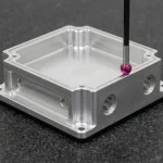
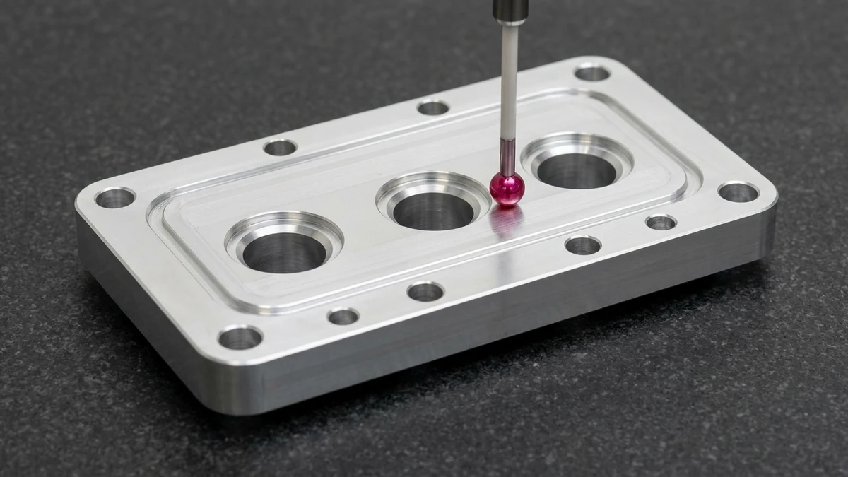
Component-level DFM achieves peak cost reduction when paired with assembly consolidation and functional ASME Y14.5 datum locking. As shown on the bare-metal 6061-T6 hydraulic valve manifold below—where a Zeiss CMM ruby stylus probes the flat primary top datum face adjacent to three stepped counterbores—anchoring tolerances to physical mating planes prevents stack-up drift:
- Six internal pocket corners specified sharp R0.5 mm (0.020″) vertical radii at 22 mm (0.866″) pocket depth (an unmachinable L/D = 22:1 ratio for a Ø1.0 mm end mill), requiring 4 custom copper Sinker EDM electrodes.
- Blanket ±0.010 mm (±0.0004″) tolerance applied across 16 non-critical M3 cover clearance holes.
- Required 3 separate soft-jaw vise setups and 4 different screw thread sizes (M2.5, M3, M4, M5).
- Enlarged vertical pocket radii to R3.5 mm (0.138″, 1.17 × r_tool) at 22 mm depth and added 1.5° sidewall draft, enabling high-speed circular milling with rigid Ø6.0 mm (0.236″) carbide tools at L/D = 3.67:1 ≤ 4:1 (0 EDM burns).
- Relaxed clearance holes to ISO 2768-mK while holding ±0.010 mm (±0.0004″) strictly on valve spool bores.
- Consolidated machining into 1 indexed 4-axis setup and unified all fasteners to M4×16 mm.
| Key Production Metric | Initial Non-DFM Customer CAD | DFM-Optimized Production CAD | Engineering Benchmark ROI |
|---|---|---|---|
| CNC Spindle Cycle Time | 114 minutes / part | 62 minutes / part | −45.6% Spindle Run Time |
| Secondary Sinker EDM Tooling | 4 Custom Copper Electrodes (R0.5 mm at 22 mm) | 0 Electrodes (100% Milled via R3.5 mm / Ø6.0 mm, L/D = 3.67:1) | 100% EDM Surcharge Eliminated |
| Workholding Setup Count | 3 Manual Soft-Jaw Vise Setups | 1 Consolidated 4-Axis Indexed Setup | −66.7% Setup & Datum Stack Error |
| Batch Scrap Rate (500-pc Pilot Run) | 6.8% (34 pcs: deep corner chatter & taper) | 0.2% (1 pc per 500-pc run) | −97.1% Scrap Reduction |
| Relative Unit Manufacturing Cost | 1.60× Baseline Cost Index | 1.00× Optimized Cost Index | −37.5% Net Unit Cost Savings |
6. The 15-Point Pre-Flight DFM Checklist & Cross-Process Selection Matrix
Before releasing your 3D CAD package (STEP/Parasolid + 2D PDF drawing) for production, audit critical features against our 15-point pre-flight checklist and cross-process capability matrix below. All turnaround windows denote Ex-Factory Production & Inspection Turnaround in business days, excluding 3–5 business days of international DHL/FedEx/UPS air transit:
| No. | Engineering Checkpoint | Target Process | Golden DFM Design Threshold | Shop-Floor Failure Mode Prevented |
|---|---|---|---|---|
| 01 | Internal Vertical Pocket Radii | CNC Milling | R ≥ 1/3 × Depth (or R ≥ 1.15 × r_tool) | Eliminates corner chatter and secondary Sinker EDM burns |
| 02 | Pocket Depth-to-Diameter Ratio | CNC Milling | L/D ≤ 4:1 (Al) / L/D ≤ 3:1 (Stainless & Ti) | Prevents cantilever cutter deflection (δ ∝ L³/D⁴) and wall taper |
| 03 | Minimum Wall Thickness | CNC Machining | T ≥ 0.8–1.0 mm (Metals) / ≥ 1.5 mm (Plastics) | Prevents harmonic vibration flutter and unclamping bow |
| 04 | Blind Tapped Hole Clearance | CNC Tapping | 1.5D–2.0D threads + ≥ 0.5D unthreaded pilot | Prevents chip packing at drill cone and tap breakage |
| 05 | Flush Mating Corner Relief | CNC Milling | Dog-bone or T-bone circular corner undercut | Allows square PCBs and mating plates to seat 100% flush |
| 06 | Corner Bend Relief Notches | Sheet Metal | Width W ≥ t (min 1.5 mm); Depth L ≥ R_in + t | Isolates folding strain and prevents corner shear tearing |
| 07 | Hole-to-Bend Line Setback | Sheet Metal | D_hole-to-bend ≥ 2.5 × t + R_in | Keeps mounting holes and slots distortion-free outside bend zone |
| 08 | Unified Inside Bend Radius | Sheet Metal | R_in = 1.0 × t (5052-H32/304/SPCC; 3.0–6.0t on 6061-T6) | Eliminates mid-run V-die swaps and outer-grain cracking |
| 09 | Screw Boss Coring & Gussets | Injection Molding | T_boss = 0.60 × T_wall braced with 3–4 gussets | Eliminates thick root mass voids and Class-A sink craters |
| 10 | Vertical Wall Draft Angles | Injection Molding | 0.5°–1.0° polished (+1.0°–1.5° per 0.025 mm texture) | Breaks core grip and prevents VDI/Mold-Tech drag scuffing |
| 11 | Reinforcing Rib-to-Wall Ratio | Injection Molding | T_rib ≤ 0.50–0.60 × T_wall; Height ≤ 3 × T_wall | Provides bending stiffness without opposite-side sink lines |
| 12 | Self-Supporting AM Overhangs | Metal / Resin 3D Print | Overhang angle ≥ 45°; teardrop horizontal bores | Eliminates internal support scarring and roof dross collapse |
| 13 | Hollow Cavity Powder Drains | SLS / MJF / DMLS | ≥ 2 opposed drain holes (Ø ≥ 4.0–6.0 mm) | Enables complete evacuation of unsintered powder cake |
| 14 | Coating Dimensional Offset | Surface Finishing | Mask H7 bores/threads; 50 μm Type III grows ~25 μm/side | Prevents bore shrinkage (~0.05 mm) and thread binding after coating |
| 15 | Selective Critical Tolerancing | All Processes | ISO 2768-mK general; ±0.010–0.020 mm only on fits | Avoids 2×–5× cycle time and 100% CMM inspection surcharges |
| Manufacturing Discipline | Standard & Precision Tolerances | Ex-Factory Turnaround (Business Days) | Primary Geometric DFM Rules | Recommended Application / When to Choose |
|---|---|---|---|---|
| CNC Milling & Turning | ISO 2768-mK | Fits: ±0.010–0.020 mm (Grind/EDM/Swiss: ±0.005 mm) | 4–8 Business Days (Proto) | 7–30 Business Days (Prod) | R_corner ≥ 1.15×r_tool; Pocket L/D ≤ 4:1; Wall ≥ 1.0 mm; +0.5D tap relief | 1 to 1,000+ pcs: Structural brackets, manifolds, precision shafts & impellers |
| Sheet Metal Fabrication | Laser Cut: ±0.10–0.20 mm | Bend: ±0.20–0.40 mm, ±0.5°–1.0° | 4–8 Business Days (Bare) | 7–12 Business Days (Coated) | Uniform gauge t; R_in ≥ 1.0t (5052-H32); Setback ≥ 2.5t+R_in; Flange ≥ 4t+R_in | 1 to 5,000+ pcs: Server chassis, U-brackets, enclosures & copper busbars |
| Plastic Injection Molding | ISO 20457 (TG4–TG6) | Tight Features: ±0.05–0.10 mm | 12–18 Business Days (Rapid T1) | 18–35 Business Days (Prod) | Uniform 1.5–3.0 mm wall; Rib = 50%–60% wall; Cored bosses; 0.5°–2.0° draft | 500 to 1,000,000+ pcs: Molded housings, overmolded gears & medical parts |
| Polyurethane Vacuum Casting | ISO 3302-1 (Elastomers) | PU Castings: ±0.15 mm (or ±0.15%–0.25%) | 7–12 Business Days (Ex-Factory) | Wall 1.5–3.0 mm; +0.2% master shrink scale; knurled brass inserts | 10 to 100 pcs: Pre-series bridge housings, clear lenses & Shore A overmolds |
| Industrial 3D Printing | 4K DLP: ±0.025–0.050 mm | SLA/SLS/MJF/DMLS: ±0.10–0.20 mm | 4–8 Business Days (Raw) | 7–12 Business Days (Finished) | Overhang ≥ 45°; ≥2 powder drain holes (Ø≥4 mm); +0.8 mm CNC stock on DMLS | 1 to 500 pcs: 4K Micro-DLP connectors, MJF manifolds & conformal channels |
7. Frequently Asked Questions (FAQ) on Engineering DFM Reviews
Q1: Does AS Prototypes provide a complimentary DFM review before machining or cutting mold steel?
Q2: Why should I use ISO 2768-mK general tolerances with selective ±0.010 mm callouts instead of blanket tight tolerances?
Q3: How do you verify GD&T tolerances across CNC metal parts vs. sheet metal and polymer 3D printed parts?
Q4: Which 3D CAD and 2D drawing file formats are required for an accurate DFM review?
Q5: How is our intellectual property (IP) protected when submitting CAD files for DFM analysis?
Ready to Optimize Your 3D CAD for Cost-Effective Manufacturing?
✔ Strict Mutual NDA Confidentiality
✔ Complimentary 24-Hour DFM Redline Report
✔ Full FAI & Zeiss CMM / 2.5D Optical VMS Inspection