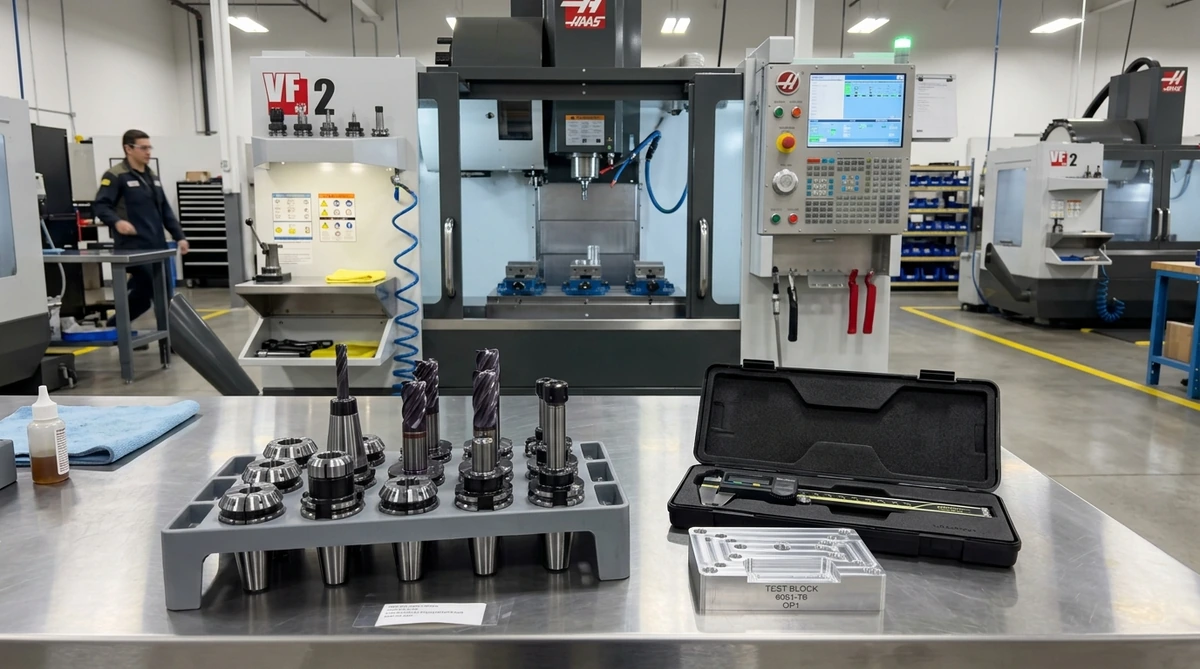
Mastering CNC machining for beginners requires a solid grasp of machine kinematics, cutting tool dynamics, and workpiece fixture stability. Computer Numerical Control (CNC) technology transforms raw metal billets and engineered plastics into high-precision prototypes. For junior engineers and aspiring machinists, learning how software toolpaths translate into physical chip formation is the fastest path to manufacturing excellence.
Modern machine shops rely on digital instructions known as G-code and M-code. These numerical codes control spindle rotation speed, multi-axis table positioning, and coolant flow. However, successfully operating a milling machine or lathe involves far more than simply pressing a cycle start button. You must understand how tool deflection, thermal expansion, and clamping forces affect final part tolerances.
Core Fundamentals: How CNC Machines Remove Material
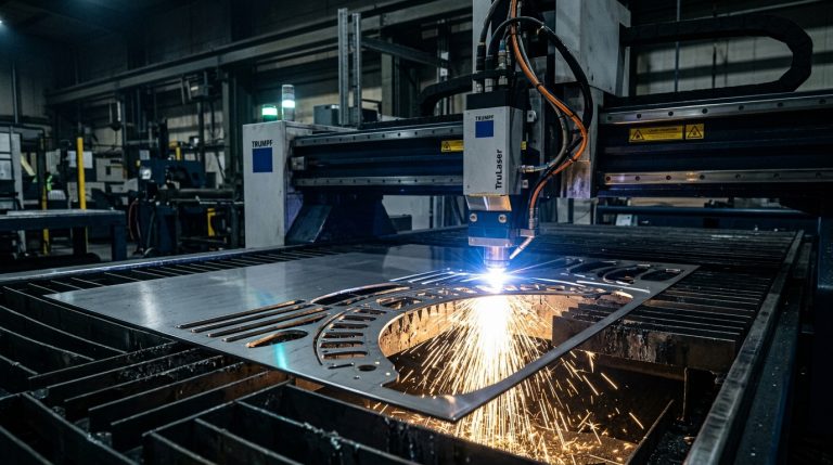
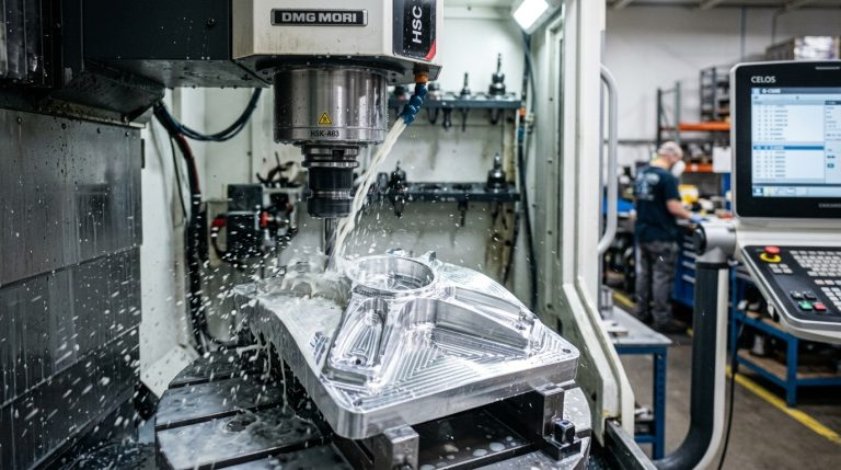
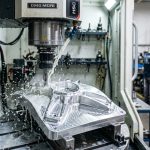
Subtractive manufacturing removes material by shearing metal or polymer stock along planned geometric boundaries. In CNC milling, a rotating cutting tool engages a stationary workpiece clamped to the machine bed. Conversely, CNC turning rotates a cylindrical bar against a stationary single-point cutting insert.
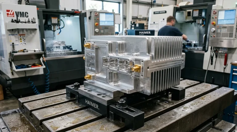
Whether configuring a 3-axis vertical machining center or an advanced 5-axis platform, mechanical rigidity is essential. Even microscopic vibrations degrade surface roughness and accelerate tool wear. At AS Prototypes, our precision CNC machining services utilize heavy cast-iron beds and preloaded linear guideways to eliminate mechanical backlash.
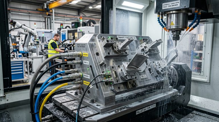
Crucial Pre-Operation Setup and Workholding
Flawless parts begin with meticulous machine setup. Before executing any CAM program, machinists must establish reference datums and verify cutting tool geometries:
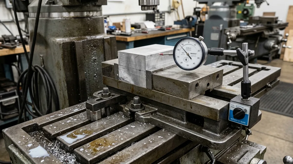
- Tramming and Alignment: Mount a dial test indicator on the spindle nose to sweep the solid vise jaw. Parallelism along the X-axis must remain within ±0.005 mm across the entire jaw width.
- Setting Work Coordinate Systems (WCS): Establish part zero (G54 through G59) using an electronic 3D edge finder or infrared spindle probe. Always double-check Z-axis touch-offs to prevent accidental spindle crashes.
- Tool Length Offsets (TLO): Measure tool stick-out lengths using a precision optical tool presetter or mechanical contact sensor. Store exact corner radii and flute lengths inside the tool geometry table.
- Dry Runs and Distance-To-Go: Always execute your first program run with Z-axis work coordinate elevated 50 mm above the raw stock. Monitor the “distance-to-go” digital display on the CNC control panel before engaging live material.
When milling complex geometric pockets, toolpath selection significantly influences tool life. Advanced multi-axis CNC milling software utilizes adaptive clearing strategies to maintain a constant radial engagement angle, preventing cutter shock loading.
Troubleshooting Common Beginner Machining Challenges
Beginner operators inevitably encounter machining anomalies during initial production runs. The table below outlines root causes and proven engineering remedies for frequent shop floor issues:
| Machining Challenge | Physical Root Cause | Auditory / Visual Symptom | Corrective Action |
|---|---|---|---|
| Tool Chatter & Vibration | Excessive tool overhang or harmonic resonance | High-pitch squeal; wavy ripple marks on sidewalls | Shorten tool extension; adjust spindle RPM by ±15% |
| Built-Up Edge (BUE) | Ductile chips welding onto the cutting edge | Dull cloudy finish; torn aluminum grain structure | Increase cutting speed (Vc); boost flood coolant pressure |
| Dimensional Drift | Spindle thermal growth or workpiece temperature rise | Parts slowly oversize across consecutive cycles | Perform spindle warm-up cycle; monitor ambient shop temp |
| Premature Chipping | Excessive chip load during initial cut entry | Sharp clicking sound; micro-fractured carbide flutes | Use helical ramping entry instead of direct vertical plunging |
| Part Warpage | Release of internal residual stress or over-clamping | Part bows immediately after releasing vise jaws | Rough all faces before finishing; reduce clamping torque |
Feeds, Speeds, and Tooling Selection for Beginners
Calculating proper speeds and feeds prevents tool breakage and ensures pristine surface finishes. Spindle speed (RPM) depends on the cutting speed (Vc in meters per minute) and tool diameter. Meanwhile, feed rate depends on the chip load per tooth (fz). The table below details recommended starting parameters for common prototyping materials:
| Workpiece Material | Tooling Substrate & Coating | Cutting Speed Vc (m/min) | Feed per Tooth fz (mm/flute) | Recommended Coolant |
|---|---|---|---|---|
| Aluminum 6061-T6 | Solid Carbide (Uncoated / ZrN) | 250 – 450 | 0.05 – 0.12 | High-pressure water-soluble emulsion |
| Stainless Steel 304 | Micro-grain Carbide (AlTiN coated) | 80 – 140 | 0.03 – 0.06 | Flood coolant with EP anti-wear additives |
| POM-C (Acetal / Delrin) | Polished Carbide (Single or 2 Flute) | 200 – 350 | 0.08 – 0.15 | Dry with high-pressure air blast |
| Titanium Ti-6Al-4V | Ultra-fine micro-grain carbide (TiAlSiN) | 45 – 70 | 0.03 – 0.05 | High-volume through-spindle flood coolant |
The most critical step is verifying your work coordinate system (WCS) and tool length offsets. Even a minor entry error in Z-axis touch-off can cause violent spindle tool crashes into the vise or machine table. Always conduct a dry run above the raw stock to verify cutter clearance.
Tool chatter primarily stems from excessive cutter overhang and aggressive radial depths of cut. When the tool stick-out exceeds three to four times its shank diameter, cutting forces cause the cutter to flex and oscillate. Machinists should choke up on the tool shank or adjust spindle speed to break harmonic resonance.
AS Prototypes maintains tight ISO 2768-mK and precision fH tolerances through temperature-controlled manufacturing facilities and calibrated CMM coordinate metrology. We utilize dedicated hydraulic fixtures and pre-ground carbide tooling to achieve repeatable accuracy down to plus or minus 0.005 mm.
Take Your Custom Machining Projects to Production
Whether you are designing your first custom mechanical assembly or optimizing production tooling, AS Prototypes brings over a decade of precision CNC machining expertise to your team. Upload your 3D CAD models (STEP, IGES, or DXF) to receive immediate DFM feedback, tolerance recommendations, and competitive pricing within 24 hours.