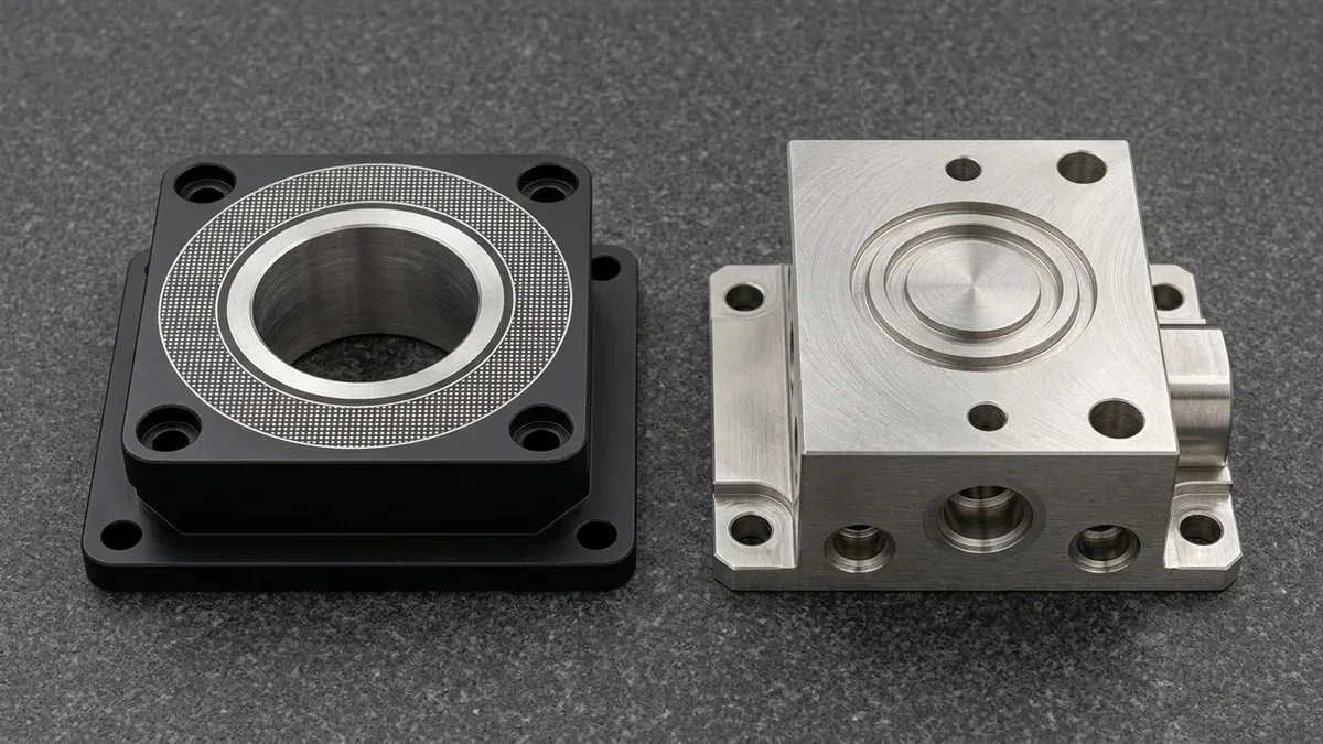
Product traceability and permanent component identification represent critical requirements in modern mechanical manufacturing. Consequently, engineers frequently compare laser etching vs engraving when specifying part identification protocols. While both methods utilize focused industrial laser beams, their underlying beam-material interactions differ substantially.
Furthermore, choosing the incorrect laser process can degrade thin-walled sheet metal or compromise corrosion resistance. In this comprehensive technical guide, our manufacturing engineers evaluate laser etching, laser engraving, and laser annealing. In shop-floor practice, we analyze penetration depths, cycle times, surface metallurgy, and material compatibility.
Executive Summary & Engineering Takeaways (BLUF)
- Three Thermal Regimes by Fluence: Industrial galvo laser marking operates across three distinct energy-density (fluence, J/cm²) regimes: Laser Annealing (0.000 mm depth, sub-melting thermal oxidation), Laser Etching (<0.025 mm / 0.001″ micro-melt expansion or coating ablation), and Deep Laser Engraving (0.050–0.500 mm / 0.002″–0.020″ vaporization cavity).
- Anodized Aluminum Contrast Mechanism: Marking MIL-A-8625 Type II/III dyed anodized aluminum with a 1,064 nm MOPA fiber laser (2–20 ns pulse duration) bleaches the organic dye and micro-textures only the outer 2–5 μm porous oxide layer—producing bright, permanent silver-white graphics (>85% Michelson contrast) without exposing raw aluminum to corrosion.
- Zero-Ablation Medical Laser Annealing: For 316L/17-4PH stainless steel surgical instruments and Ti-6Al-4V orthopedic hardware, defocused laser annealing heats the top 20–30 μm to 250°C–450°C (482°F–842°F)—strictly below the melting and carbide-sensitization thresholds—growing a smooth, burr-free dark oxide layer (Cr2O3/Fe3O4 spinel on stainless steel; TiO2 interference film on titanium) that survives autoclave sterilization and ASTM A967 passivation.
- Galvo Field & Curvature DFM: F-theta telecentric lenses maintain focal spot uniformity across flat zones or cylindrical surfaces up to ±1.5 mm (±0.060″) depth of focus; wrap-around markings exceeding 30° arc angle require synchronized 4th-axis rotary chuck indexing.
Article Engineering Navigation
- 1. Beam Physics: Laser Etching vs Laser Engraving
- 2. Process Comparison and Material Compatibility
- 3. Laser Annealing: The Zero-Ablation Medical Solution
- 4. DFM Recommendations for Industrial Laser Marking
- 5. Quantitative Laser Fluence, Ablation Depth & Thermal Annealing Physics
- 6. Why Do Laser Marks Fade After Passivation, Autoclaving, or Shot Peening?
- 7. When NOT to Use Deep Laser Engraving & Part Marking DFM Checklist
- 8. Technical Engineering FAQ
1. Beam Physics: Laser Etching vs Laser Engraving
Core Physical Principles and Shop-Floor Execution
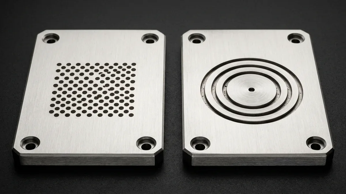
The primary distinction between laser etching and laser engraving lies in the applied energy density and material removal mechanism. For example, laser etching delivers lower peak pulse energy to melt the substrate locally. As the molten pool expands, it resolidifies into a slightly raised, high-contrast textured micro-relief.
Conversely, laser engraving applies extremely high concentrated peak irradiance. The intense laser energy rapidly heats the target material beyond its vaporization temperature. Therefore, laser engraving cleanly ablates material, carving deep, permanent physical cavities into the workpiece.
| Process Parameter | Laser Etching | Laser Engraving | Laser Annealing |
|---|---|---|---|
| Material Mechanism | Surface melting and thermal expansion | Vaporization and material ablation | Localized subsurface oxidation |
| Marking Depth | Less than 0.025 mm (Shallow Micro-Melt) | 0.05 mm to 0.50 mm (Deep) | Zero material depth change (Flat) |
| Surface Texture | Slightly raised micro-frosting | Recessed groove with defined edges | Completely smooth passivated surface |
| Production Speed | Very fast (High pulse frequency) | Moderate to slow (Multiple passes) | Slow (Controlled thermal diffusion) |
| Durability Level | Resistant to mild handling wear | Permanent under extreme mechanical abrasion | Corrosion proof and autoclave safe |
| Typical Parts | Barcodes, serial tags, thin brackets | VIN plates, tire molds, firearm receivers | Surgical tools, orthopedic bone plates |
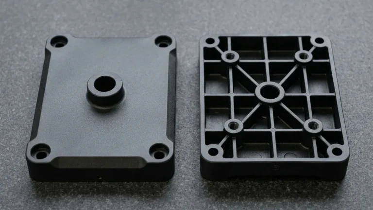
Figure 1 provides a direct side-by-side comparison on two brushed 316L stainless steel manifold plates resting on black granite: the left plate exhibits a shallow micro-melted laser-etched geometric dot-matrix pattern, whereas the right plate displays a deep laser-engraved concentric alignment groove with ablated vertical sidewalls.
2. Process Comparison and Material Compatibility
Primary Process Capabilities and Equipment Architecture
Selecting the optimal laser wavelength and pulse duration depends heavily on the workpiece alloy composition. For bare steels, aluminum, and brass, 1064 nm fiber lasers provide high absorption efficiency. Furthermore, fiber lasers generate crisp optical contrast without requiring messy chemical etching pastes.
In addition, laser etching is the preferred approach for black or clear anodized aluminum. High-speed laser pulses ablate the micro-porous dye layer, revealing pristine white aluminum oxide beneath. Review our full range of protective precision surface finishing services for anodized coatings.
Material Compatibility and Geometric Design Boundaries
Meanwhile, deep laser engraving remains indispensable for parts subjected to subsequent powder coating or heavy abrasive blast cleaning. Because engraving cuts up to 0.5 mm deep, characters remain perfectly legible after paint curing. Explore our custom precision sheet metal fabrication capabilities for durable industrial chassis enclosures.
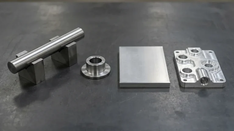
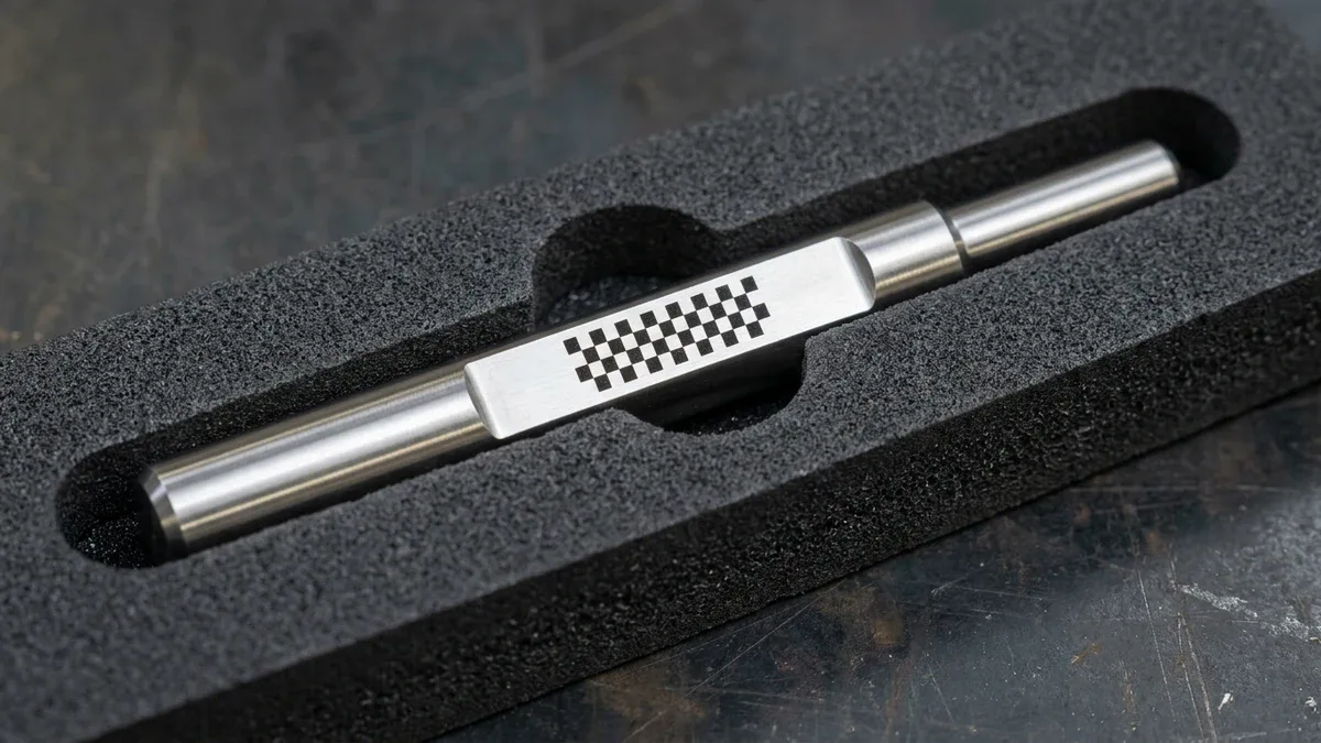
For medical and corrosion-critical instruments, Figure 2 shows a passivated 316L stainless steel stepped surgical shaft in an EVA tray featuring a high-contrast black laser-annealed geometric checkerboard mark. Defocused sub-melting laser annealing forms a smooth chromium-iron oxide layer with zero surface material removal.
3. Laser Annealing: The Zero-Ablation Medical Solution
Critical Process Parameters and Tooling Selection
Certain high-reliability applications cannot tolerate surface micro-cracks or material removal. Specifically, surgical instruments and orthopedic titanium implants require completely smooth surfaces. In these critical environments, engineers specify laser annealing rather than deep laser engraving.
During laser annealing, a defocused beam gently heats the steel or titanium below its melting threshold. Consequently, controlled thermal oxidation creates a deep black or iridescent mark beneath the passive oxide film. Therefore, the component retains its pristine surface finish, passivated corrosion barrier, and biocompatibility.
4. DFM Recommendations for Industrial Laser Marking
Practical Design-for-Manufacturing (DFM) Guidelines
To ensure high marking throughput and legible machine vision readability, follow standard design for manufacturability rules. First, maintain minimum character heights above 0.8 mm for alphanumeric serial numbers. Smaller font sizes risk optical blurring when scanning with standard handheld industrial barcode readers.
Second, specify laser marking on accessible flat surfaces perpendicular to the galvo laser scanning head. While 3D dynamic focusing heads can mark curved contours, flat planes maximize laser focus depth and processing speed. Finally, clearly define marking depth requirements on 2D engineering drawings to avoid over-engraving delicate thin-walled features.
5. Quantitative Laser Fluence, Ablation Depth & Thermal Annealing Physics
Pulse Energy Fluence Thresholds and Thermal Diffusion Depth
The physical distinction between laser annealing, laser etching, and deep laser engraving is governed by optical energy fluence (F, measured in J/cm²) and laser pulse duration (τp). When a 1,064 nm Ytterbium MOPA fiber laser focuses a Gaussian beam of spot radius w0 (typically 15–35 μm) onto a metal surface, the peak power density determines whether the metal oxidizes solid-state, melts locally, or vaporizes into plasma.
• Optical Pulse Fluence: F = (2 × Epulse) / (π × w0²) [J/cm²] (where Epulse = Pavg / frep)
• Thermal Diffusion Depth per Pulse: Lth = √(4 × αdiff × τpulse) [μm] (where αdiff = thermal diffusivity)
• Beer-Lambert Ablation Depth per Pass: zablate ≈ (1 / μeff) × ln(F / Fth) [μm] (for F > ablation threshold Fth)
Laser Annealing (Zero Material Removal) vs. Etching (< 25 μm) vs. Engraving (25–500 μm)
In laser annealing (used extensively on 316L and 17-4PH stainless steel surgical instruments and titanium implants), a slightly defocused beam heats the metal surface to 250°C–450°C—strictly below the melting point—growing a smooth, 100–300 nm interference oxide film with zero material removal (Δz = 0 μm).
Laser etching increases fluence past the melting threshold to create a micro-textured surface (depth ≤ 25 μm / 0.001 in), whereas deep laser engraving vaporizes material across multiple passes to reach 50–500 μm (0.002–0.020 in) trench depths.
MOPA Nanosecond vs. Picosecond Ultrashort Pulse Marking on Anodized Aluminum
When marking black or colored MIL-A-8625 Type II/III anodized 6061-T6 aluminum enclosures, short-pulse MOPA fiber lasers (τp = 2–8 ns at 200–500 kHz) bleach the organic dye inside the anodic pores to produce a high-contrast bright white mark without cracking the protective Al2O3 barrier layer, preserving ASTM B117 salt-spray corrosion resistance.
6. Why Do Laser Marks Fade After Passivation, Autoclaving, or Shot Peening?
Preventing Chromium Depletion and Red Rust on Medical Stainless Steel Marks
If a laser operator runs excessive pulse energy or slow scan speeds during stainless steel marking, local surface temperatures dwell in the 450°C–850°C sensitization window—or exceed 850°C into surface micro-melting—precipitating chromium carbides (Cr23C6) at grain boundaries and depleting free chromium below the 12% threshold required for a passive Cr2O3 film. During subsequent ASTM A967 nitric/citric acid passivation or hospital steam autoclaving, these sensitized laser marks corrode and bleed red rust.
| Observed Defect / Symptom | Physical Root Cause | Quantitative Process Threshold | Corrective Shop-Floor Action | Inspection Verification Method |
|---|---|---|---|---|
| Red rust corrosion on 316L/17-4PH laser mark after passivation | Excessive heat input causing chromium carbide sensitization and surface micro-cracking | Peak surface temperature entering the 450°C–850°C sensitization range or surface melting (>1,400°C) | Switch to low-fluence defocused annealing or ultrashort picosecond pulses, followed by citric acid passivation | ASTM A967 Copper Sulfate (CuSO4) test and 100-cycle steam autoclave validation |
| Low barcode contrast or corrosion on anodized aluminum | Long pulse duration (> 100 ns) ablating through the anodic oxide down to bare 6061 base metal | Ablation depth exceeds anodic film thickness (8–20 μm Type II) | Use MOPA fiber laser at 2–4 ns pulse width and high repetition rate (300 kHz) to bleach dye without stripping oxide | ISO/IEC 15415 DataMatrix barcode verifier (Grade A/B contrast) and eddy-current film check |
| Fatigue crack initiation from deep engraved serial numbers | Sharp thermal recast layer and micro-notches acting as stress risers under cyclic load | Engraving depth > 50 μm (0.002 in) inside high-stress fillet or tensile zone | Relocate marking zone to low-stress neutral axis pad and use shallow laser etching (< 12 μm) or dot-peen with rounded stylus | Metallographic cross-section for Heat-Affected Zone (HAZ < 10 μm) and dye penetrant check |
| Foaming, charring, or unreadable marks on dark plastics | Incorrect laser wavelength absorption in uncompounded polymer matrix | 1,064 nm IR beam transmitting too deeply without TiO2 or carbon laser-mark additive | Switch to 355 nm UV cold-ablation laser for unfilled plastics or specify 0.5% laser-sensitive additive in resin | Optical barcode scanner verification and rub/solvent durability test |
ISO/IEC 15415 Direct Part Marking (DPM) DataMatrix Verification
For automotive, aerospace, and medical UDI traceability, 2D DataMatrix codes must maintain a quiet zone of at least 1× module width around the perimeter and keep cell modulation contrast above Grade B (≥ 2.5) under ISO/IEC 15415 / AIM DPM-1-2006 dome and low-angle lighting verification.
7. When NOT to Use Deep Laser Engraving & Part Marking DFM Checklist
When NOT to Call Out Deep Laser Engraving on Engineering Drawings
Design engineers should avoid specifying deep laser engraving (50–300 μm depth) under three critical operating conditions:
- Fatigue-Critical Dynamic Aerospace and Motorsport Components: Deep thermal engraving leaves a brittle recast layer and sharp root micro-cracks that reduce high-cycle fatigue life by 25%–40%; specify shallow surface annealing or low-stress chemical etching in a designated non-stressed zone.
- Thin-Film Protective Coatings Without Post-Coating Allowance: Engraving through a finished Type II anodized, zinc-nickel plated, or passivated surface exposes raw substrate metal unless the mark is applied BEFORE plating or executed via non-ablative oxide annealing.
- Curved Cylindrical Shafts Over 30° Arc Without Rotary Indexing: Marking across a steep cylinder radius on a fixed-focus 2-axis XY galvo head pushes the outer characters out of the F-theta lens focal depth (DOF ≈ ±0.5 mm), causing uneven depth and faded edges; specify 4th-axis rotary synchronized marking.
Four-Step Laser Etching & Engraving DFM Specification Protocol
- State Exact Process Sequence Relative to Surface Treatment: Explicitly note on the 2D drawing whether laser marking occurs “Mark BEFORE Anodize/Passivate” (for deep engraved cavities) or “Laser Anneal/Bleach AFTER Surface Finish” (for high-contrast surface marks).
- Specify Maximum Allowable Depth and HAZ for Structural Parts: Call out “Laser Etch: Depth ≤ 0.015 mm (0.0006 in)” or “Zero-Relief Laser Anneal (Δz = 0 mm)” rather than writing generic “Laser Engrave” on load-bearing brackets or sterile medical shafts.
- Design a Dedicated Flat Marking Pad Away from Filleted Corners: Provide a flat, unobstructed target zone at least 2.0 mm away from edges, holes, and O-ring sealing faces with surface roughness Ra ≤ 1.6 μm (63 μin).
- Define Machine-Readable Barcode Grading Standards: When calling out 2D DataMatrix or QR codes, specify minimum matrix size (e.g., 6 × 6 mm for 16×16 cells) and require ISO/IEC 15415 / AIM DPM Grade B or better verification prior to shipment.
🔗 Related Part Marking, Surface Finishing & Medical Machining Guides
8. Technical Engineering FAQ
Laser etching melts the outer <25 µm surface skin at 1,000–3,000 mm/s, whereas engraving vaporizes substrate metal into a 0.05–0.50 mm recessed cavity. Conversely, defocused laser annealing stays below the melting point to form a zero-relief dark oxide film on steel or titanium.
No; MOPA fiber laser etching with 4–15 ns pulses bleaches only the outer 2–5 µm dye layer on MIL-A-8625 anodized aluminum while preserving the barrier oxide. For deep cavities requiring ASTM B117 salt-spray immunity, always specify laser engraving before anodizing.
Laser engraving cuts a 50–200 µm trench with recast edges that disrupt the passive film, create stress risers, and trap bacteria during autoclaving. Defocused laser annealing forms a jet-black subsurface oxide mark with zero material removal (Ra unchanged), passing ASTM A967 passivation.
Specify minimum heights of 1.0 mm for readable text and 3.0 × 3.0 mm for ECC 200 DataMatrix codes to ensure optical scanner contrast. Always supply true vector outlines (DXF, AI, or EPS) on 2D drawings with exact X–Y datum coordinates and coating sequence callouts.
Ready to Validate Your CAD Design for Precision Manufacturing?
Upload your 3D CAD models (STEP, IGES, SolidWorks) and 2D engineering drawings for a comprehensive DFM engineering review and custom quotation from our in-house CNC machining and prototyping team.
Request a Custom DFM Review & Quote →