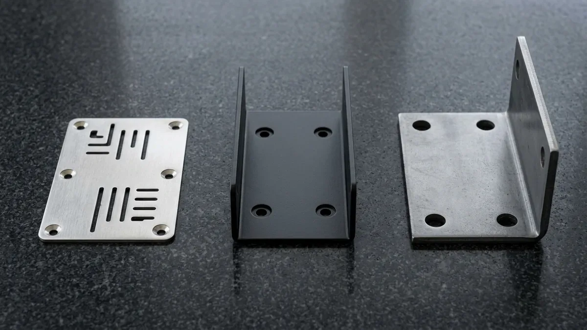
Sheet metal fabrication optimization bridges the gap between theoretical 2D CAD flat patterns and functional 3D precision assemblies. Successful production depends on accurate plastic deformation modeling (K-factor neutral axis shifts), disciplined geometric clearances, and automated downstream processing.
- 1. The Physics of Sheet Metal Bending: Neutral Axis & K-Factor Mechanics
- 2. Flat Blanking Technologies: Fiber Laser Cutting vs CNC Turret Punching
- 3. Press Brake Tooling: Air Bending Dynamics, V-Die Selection & Tonnage
- 4. The 7 Critical DFM Rules for Precision Sheet Metal Forming
- 5. Engineering Material Selection: Alloys, Grain Orientation & Formability
- 6. Hardware Integration: Self-Clinching PEM Fasteners & Standoff DFM
- 7. Joining & Finishing: Laser Welding, Conversion Coatings & Powder Coating
- 8. Quality Assurance & Inspection: Mating Fit-Up, Checking Fixtures & Flange Gauging
- 9. Shop-Floor Defect Troubleshooting & Root-Cause Countermeasures
- 10. Technical Engineering FAQ
1. The Physics of Sheet Metal Bending: Neutral Axis & K-Factor Mechanics
Precision sheet metal fabrication is the foundational backbone of industrial telecommunications racks, aerospace avionics bays, server chassis, and medical diagnostic enclosures. Transforming a 2D blank into a structurally rigid 3D enclosure requires precise management of elastoplastic mechanics. During press brake bending, the sheet metal cross-section undergoes two opposing stress regimes simultaneously: the exterior radius experiences severe tensile strain and elongation, while the interior radius undergoes intense compressive deformation and material thickening.
Between these two opposing zones lies the neutral axis—a theoretical plane within the material that experiences zero longitudinal stress and zero dimensional change. In an unstrained, flat condition, this axis sits at the geometric center of the sheet thickness (t / T = 0.50). However, as compressive stresses expand the inner plastic zone more rapidly than tensile thinning on the outside, the neutral axis migrates inward toward the punch tip. Calculating the exact location of this shifted neutral axis is the single most critical factor in predicting flat blank expansion.
The Mathematical Derivation of K-Factor and Bend Allowance
The K-factor is defined as the dimensionless ratio representing the neutral axis position (t) relative to the total material thickness (T):
Because metal expands along the outer perimeter while compressing along the inside, the arc length along the shifted neutral axis defines the exact amount of material consumed by the curved section of the bend. This arc length is the Bend Allowance (BA), calculated as:
Where Rin is the inside bend radius, T is the sheet material thickness, and θ is the total bend angle in degrees. In automated CAD/CAM sheet metal unfolders (such as SolidWorks, PTC Creo, or Siemens NX), production technicians frequently utilize Bend Deduction (BD) or Outside Setback (OSSB) to calculate the developed flat blank length directly from the part’s outside apex dimensions:
BD = 2 · OSSB − BA
Lflat = Lleg1 + Lleg2 − BD
For a standard 90° bend, tan(45°) = 1.0, simplifying the outside setback to OSSB = Rin + T. If an engineering drawing specifies an inside bend radius of 2.0 mm on a 2.0 mm thick 5052-H32 aluminum panel (with K = 0.40) bent at 90°, the bend allowance calculates to BA = (3.14159 / 180) · 90 · (2.0 + 0.40 · 2.0) = 4.398 mm.
The outside setback is OSSB = 2.0 + 2.0 = 4.0 mm, yielding a bend deduction of BD = (2 · 4.0) − 4.398 = 3.602 mm. Applying an incorrect default K-factor (such as generic 0.50) across a complex chassis with 8 consecutive bends introduces a cumulative dimensional error exceeding 2.2 mm, causing screw holes, connector cutouts, and mating seams to drift out of specification.
| Material Alloy & Temper | Tensile Strength (MPa) | Typical K-Factor (Air Bending) | Recommended Inside Radius (Rmin) | Formability Characteristic |
|---|---|---|---|---|
| Aluminum 5052-H32 | 210 – 260 | 0.38 – 0.42 | 1.0 · T | Exceptional ductility, tight bends without cracking |
| Aluminum 6061-T6 | 290 – 320 | 0.42 – 0.45 | 3.0 – 6.0 · T | High structural rigidity; cracks sharply at tight radii (use 5052-H32 for formed chassis) |
| Stainless Steel 304 (Annealed) | 520 – 650 | 0.42 – 0.46 | 1.0 – 1.5 · T | High work hardening; elevated tonnage & springback |
| Stainless Steel 316L | 490 – 620 | 0.42 – 0.46 | 1.0 – 1.5 · T | Superior pitting resistance; stable plastic elongation |
| Cold-Rolled Steel (SPCC / 1008) | 270 – 380 | 0.38 – 0.42 | 0.8 – 1.0 · T | Benchmark forming steel; consistent neutral axis behavior |
| Galvanized Steel (SECC / SGCC) | 280 – 400 | 0.38 – 0.42 | 1.0 · T | Zinc coating requires adequate radius to avoid coating flaking |
| Copper C1100 (ETP 1/2 Hard) | 240 – 300 | 0.35 – 0.40 | 0.8 – 1.0 · T | Ductile; ideal for bent power distribution busbars |
2. Flat Blanking Technologies: Fiber Laser Cutting vs CNC Turret Punching
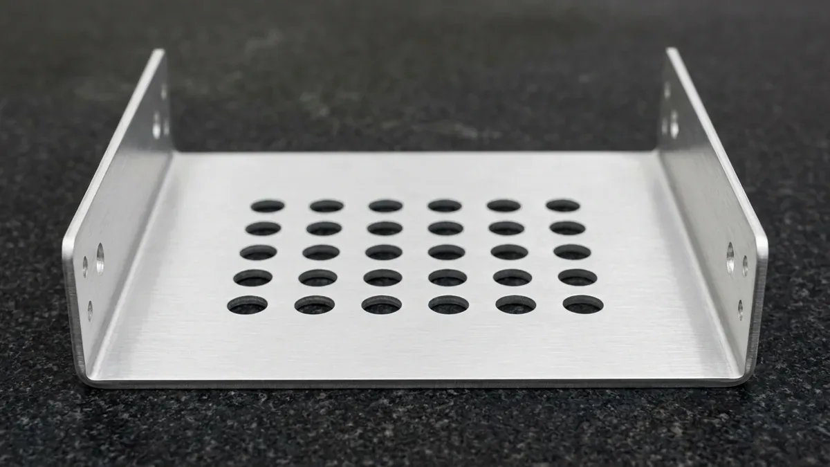
Before a sheet metal part can be folded into shape, it must be blanked from flat raw stock. The blanking process establishes edge squareness, hole pitch accuracy, perimeter deburring requirements, and overall part cost. In our sheet metal fabrication facility, modern flat blanking relies primarily on two complementary technologies: high-brightness CNC fiber laser cutting and high-speed CNC turret punching.
High-Power Fiber Laser Cutting: Kerf Dynamics & Assist Gases
Fiber laser cutting systems utilizing 4kW to 12kW solid-state optical resonators focus energy into an ultra-narrow spot diameter (typically 0.08 mm to 0.15 mm). This tight beam concentration delivers narrow kerf widths, minimal thermal heat-affected zones (HAZ), and positional positioning accuracy within ±0.05 mm across large 1500 × 3000 mm sheet formats. The mechanical performance of the laser-cut edge is fundamentally governed by the assist gas delivery system:
- High-Pressure Nitrogen (N2) Assist (18 – 25 bar): Nitrogen functions as an inert expulsion medium. The laser energy melts the parent metal, and the supersonic gas stream violently ejects molten slag downwards without reacting chemically with the substrate. This produces a bright, 100% oxidation-free metallic edge on aluminum, stainless steel, and pre-galvanized alloys. Because there is no brittle metal-oxide film, parts can proceed directly to TIG/laser welding, chromate conversion coating, or electrostatic powder coating without secondary edge grinding.
- Oxygen (O2) Assist (0.5 – 3.0 bar): Used primarily for thick carbon steel plates (SPCC, SPHC, A36). Oxygen initiates an exothermic oxidation reaction, generating significant supplemental heat that assists the laser in piercing and severing heavy plate. However, this leaves a thin carbonized iron oxide scale on the cut face. For parts designated for powder coating, this scale must be chemically etched or mechanically abraded; otherwise, the coating will delaminate when subjected to thermal cycling or ASTM B117 salt spray exposure.
Algorithmic Nesting, Lead-Ins & Micro-Joints
To optimize material utilization and prevent costly laser head collisions, our CAM programming pipeline deploys advanced geometric nesting algorithms:
- Common-Line Cutting (CLC): Where two adjacent rectangular parts share a single common cut line. CLC reduces total cutting path travel by 20% to 35%, decreases assist gas consumption, and prevents heat build-up between closely spaced contours.
- Lead-In / Lead-Out Geometries: Piercing creates a localized crater of molten slag. If pierced directly on the part contour, it leaves an unsightly notch or edge burr. We program tangential arc or diagonal lead-ins located inside internal scrap cutouts or outside the external perimeter, ensuring the beam reaches steady-state cutting speed before intercepting the functional part edge.
- Micro-Tab Placement: Small sheet metal parts (under 100 × 100 mm) cut on a slat table tend to tip upwards as they drop through the slats, creating dangerous collision hazards for the high-speed optical cutting head. Strategic CAM micro-tabs (0.3 mm to 0.8 mm bridge width) tether parts securely to the skeleton sheet during cutting, allowing rapid skeleton offloading followed by clean manual de-tabbing.
CNC Turret Punching: When Mechanical Forming Outperforms Lasers
While fiber lasers offer unmatched geometric agility for organic contours and rapid prototyping, mechanical CNC turret punches excel in high-speed repetitive hole grids and in-machine 3D sheet forms. Forming tools mounted in the turret station perform mechanical stamping directly on the flat blank without secondary press operations:
- Ventilation Louvers: Slitting and upward-drawing tools form functional airflow louvers for electrical cooling enclosures in a single stroke.
- Extruded Tapped Holes: Forming tools punch a pilot hole and extrude a vertical cylindrical collar, doubling the effective sheet thickness to permit robust thread tapping in thin stock.
- Embossments & Ribs: Shallow drawn reinforcing ribs increase panel section modulus and prevent acoustic panel vibration without adding weight.
- Countersinks & Card Guides: Coining tools produce precision countersunk screw pockets and printed circuit board (PCB) slide channels with zero swarf or chip generation.
3. Press Brake Tooling: Air Bending Dynamics, V-Die Selection & Tonnage
Mechanical press brakes utilize precision-ground punches and V-dies to deform flat sheet blanks into three-dimensional profiles. While press brake forming can be executed via coining, bottoming, or air bending, modern precision fabrication relies overwhelmingly on CNC multi-axis air bending.
Air Bending vs. Bottoming and Coining
In bottom bending (bottoming) and coining, the upper punch forces the sheet completely into contact with the root and walls of the bottom die, requiring massive hydraulic force (up to 5 to 8 times the tonnage of air bending) and causing severe tool wear.
In contrast, air bending establishes a three-point contact geometry: the sheet touches only the tip of the upper punch and the two rounded shoulder radii of the bottom V-die. The bend angle is governed entirely by the CNC ram depth penetration into the V-groove.
This provides unparalleled manufacturing agility: an operator can form 90°, 120°, 135°, and 150° angles using a single universal 88° punch and V-die set simply by altering the CNC depth parameters.
The V-Die Opening Rule of Thumb
Selecting the correct bottom V-die opening width (V) dictates the natural inside bend radius (Rin), the required bending force, and the minimum allowable flange length. For standard air bending of ductile materials, the industrial rule of thumb establishes:
- For sheet thickness T ≤ 2.5 mm: V = 6 · T to 8 · T (Natural inside radius Rin ≈ V / 6).
- For sheet thickness T > 3.0 mm: V = 8 · T to 10 · T.
- For high-strength or low-ductility alloys (6061-T6, Hardox, high-tensile steel): V = 10 · T to 12 · T.
Choosing an undersized V-die (e.g., V = 4T) forces an unnaturally tight bend radius, escalating the required forming tonnage exponentially, galling the die shoulders, and promoting tensile tearing along the outer bend crease.
Bending Tonnage Calculation & Machine Deflection
To prevent press brake structural overload and tooling fracture, the required bending force must be modeled prior to machine setup. In European and ISO sheet metal engineering, the forming force is calculated using both the SI Mechanical Force Model (in kN) and the practical Shop-Floor Metric Tonnage Model (in Metric Tons):
Fbend (kN) = [ 1.42 · σu · Lm · T2 ] / V
Shop-Floor Machine Tonnage:
Tpress (Metric Tons) = Fbend (kN) / 9.807 = [ 1.42 · σu · Lm · T2 ] / [ 9.807 · V ]
Where σu is the material ultimate tensile strength (in MPa = N/mm²), Lm is the bend length (in meters), T is the sheet thickness (in mm), and V is the bottom V-die opening width (in mm). The constant 1.42 accounts for die shoulder frictional losses and dynamic strain-hardening in air bending. For instance, bending a 1000 mm (1.0 m) long flange in 2.0 mm thick 304 stainless steel (σu ≈ 600 MPa) over a standard V = 16 mm die evaluates cleanly to:
Tpress = 213.0 / 9.807 = 21.72 Metric Tons per meter
Under this magnitude of vertical load, the press brake upper ram and lower bed experience microscopic mechanical deflection, curving slightly away from each other at the machine center. Without compensation, this deflection produces a “canoe effect”—where the flange angle reaches 90° at the outer ends of the machine but remains under-bent at 92° or 93° in the center. Our CNC press brakes incorporate dynamic hydraulic and mechanical CNC crowning beds that actively push the die bed upwards in real-time, delivering uniform angularity within ±0.5° across bend lengths up to 3 meters.
Elastic Springback Compensation
When forming force is released, the elastic strain stored within the material recovers, causing the flange angle to open slightly. This phenomenon is springback (Δθ), governed by the ratio of yield strength to modulus of elasticity (σy / E) and the ratio of inside bend radius to thickness (R / T):
Δθspringback ∝ [ σy / E ] · [ Rin / T ]
Gardiner’s Analytical Springback Ratio (Ri / Rf):
Ri / Rf = 4 · [ ( Ri · σy ) / ( E · T ) ]3 − 3 · [ ( Ri · σy ) / ( E · T ) ] + 1
Ductile mild steel (SPCC) exhibits minimal springback of 0.5° to 1.5°. In contrast, high-strength cold-worked alloys such as 304 stainless steel or hardened 6061-T6 aluminum display dramatic springback of 3.0° to 5.0° or more. To achieve a final relaxed 90° bend, our CNC press brake controllers automatically over-bend the sheet to 86.5° or 85.0°, allowing the part to spring back into an exact 90.0° target geometry upon unloading.
4. The 7 Critical DFM Rules for Precision Sheet Metal Forming
Designing sheet metal parts without adhering to fundamental tooling kinematics leads to high scrap rates, tooling gouges, distorted holes, and assembly misalignments. By integrating the following seven Design for Manufacturability (DFM) rules into your CAD workflows, you ensure smooth, cost-effective fabrication on the shop floor.
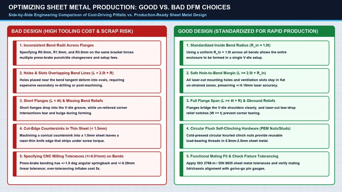
Rule 1: Maintain Uniform Minimum Inside Bend Radius (Prevent Outer Tearing)
Specifying a sharp knife-edge inside bend radius (R < 0.5T) strains the outer surface grains beyond their ultimate tensile elongation, producing micro-fractures, orange-peel crazing, or catastrophic structural splitting. As a baseline DFM standard:
- For ductile alloys (5052-H32, 1008 mild steel, C1100 copper): specify Rin ≥ 1.0 · T.
- For annealed stainless steels (304 / 316L): specify Rin ≥ 1.0 · T to 1.5 · T; for precipitation-hardened 6061-T6 aluminum sheet, cold bending requires Rin ≥ 3.0 · T to 6.0 · T to prevent outer-grain cracking (always specify 5052-H32 instead of 6061-T6 for multi-bend enclosures and brackets).
- Design Consistency: Keep all inside bend radii identical across the entire part whenever possible. Varying bend radii on a single component forces multiple tool changes or staging multi-tool setups, multiplying machine cycle times and manufacturing costs.
Rule 2: Integrate Generous Bend Relief Notches at Flange Corners
When a flange bends adjacent to an unbent flat sheet edge or between two perpendicular flanges, the material at the bend boundary undergoes intense localized transverse shear. Without stress relief, the expanding metal tears irregularly and leaves an unsightly jagged burr that bulges beyond the part perimeter.
Laser-cutting bend relief notches into the flat pattern provides a clean spatial boundary for plastic expansion. To fully isolate the forming stresses:
Relief Notch Width ≥ T (with an absolute minimum of 1.5 mm for laser cutting)
Rectangular notches are ideal for general chassis construction, while circular teardrop reliefs offer optimal stress distribution for dynamic load-bearing aerospace brackets.
Rule 3: Enforce Safe Hole-to-Bend Line Spacing (Prevent Hole Ovalization)
When a hole is positioned too close to a bend, it falls within the plastic deformation zone. As the sheet is drawn across the V-die shoulders, the tensile forces pull the hole edges toward the bend line, distorting the precision circular hole into an egg or oval shape. This distortion ruins clearance for fasteners and causes press-fit bushings or PEM standoffs to bind.
To preserve absolute circularity and dimensional integrity, the edge of any hole, slot, or cutout must sit outside the deformation zone:
Dedge-to-tangent ≥ 2.5 · T + Rin (Commercial Tolerance)
Dedge-to-tangent ≥ 3.0 · T + Rin (Critical Hardware / Cosmetic Bores)
Hole Centerline to Bend Tangent Line (CAD Dimensioning):
Dcenter-to-tangent ≥ 2.5 · T + Rin + (Øhole / 2)
If design constraints mandate placing a hole closer than 2.5T + R to the bend, add a relief slot between the hole and the bend line in the flat pattern, or laser-cut the hole as an undersized pilot and ream it to nominal size after final bending.
Rule 4: Ensure Sufficient Flange Height for Die Shoulder Support
During air bending, the sheet blank must span across both top shoulders of the V-die throughout the entire ram stroke. If a flange is designed too short, its leading edge slips off the die shoulder into the V-groove before the punch completes its downward travel. This slippage ruins the bend angle, scuffs the cosmetic surface, and creates severe operator safety hazards.
The minimum formed flange leg length (Lflange), measured from the exterior face, must satisfy:
Linside(min) ≥ (Vdie / 2) + 1.5 mm
Overall Minimum Outside Flange Height:
Houtside(min) ≥ (Vdie / 2) + Rin + T + 1.5 mm ≈ 5.0 · T + Rin + 1.5 mm (for V = 8T dies)
For a 1.5 mm thick sheet bent in an 8T (12 mm) V-die with Rin = 1.5 mm, the minimum flange height is approximately 10.5 mm (6.0 + 1.5 + 1.5 + 1.5 mm). Flanges shorter than this threshold cannot be air-bent safely and require specialized wipe tooling or secondary machining.
Rule 5: Observe Minimum Hole-to-Edge and Hole-to-Hole Distance
Laser piercing or punching holes too close to the edge of a flat blank or too close to adjacent cutouts can cause the thin connecting web of metal to bulge outwards or buckle under thermal or mechanical stress:
- Hole-to-Edge Distance: The distance between the edge of a hole and the external part perimeter should be at least 2.0 · T (minimum 1.5 mm).
- Hole-to-Hole Spacing: Maintain a minimum spacing of 2.0 · T between adjacent holes. On perforated air-intake panels with dense hole clusters, keep the bridge width at least 1.5T to preserve structural web rigidity during high-power laser thermal cycles.
Rule 6: Account for Rolling Grain Direction
Cold-rolled sheet metal is manufactured through high-pressure roller reductions, aligning the metallic crystalline grains along the rolling direction (longitudinal grain). The mechanical properties are anisotropic:
- Bending Parallel to Grain: The tensile stresses act across the elongated grain boundaries. This orientation exhibits lower fracture toughness, drastically increasing the risk of outer surface cracking, especially in work-hardened alloys like 6061-T6.
- Bending Perpendicular (or 45° Diagonal) to Grain: The bend line cuts across the crystal fibers, maximizing resistance to tensile fracture and allowing tighter bend radii. Wherever possible, nest flat patterns so critical structural bends occur at 45° to 90° relative to the sheet coil grain.
Rule 7: Manage Offset Bends (Joggles & Z-Bends)
A joggle (or Z-bend) consists of two opposing parallel bends located in close proximity. If the intermediate web length (H) between the two bends is shorter than the minimum V-die shoulder span, the sheet cannot seat properly in standard tooling for the second bend:
Hweb(min) ≥ (Vdie / 2) + Rin + 2 · T
Offset Tooling Threshold (Single-Stroke Joggle Forming):
When Hweb < (Vdie / 2) + Rin + 2 · T (step heights 2.0 mm to 6.0 mm), dedicated step tooling is deployed.
Tight joggles where the step height is small (e.g., 2.0 mm to 5.0 mm) require dedicated offset forming punch-and-die sets that strike both bends simultaneously in a single press stroke.
5. Engineering Material Selection: Alloys, Grain Orientation & Formability
Selecting the optimal sheet alloy requires balancing mechanical yield strength, weight constraints, corrosion resistance, cosmetic appearance, and press brake formability. Below is an engineering analysis of the seven most common alloys fabricated in our facility:
| Material Category | Specific Alloy Designation | Density (g/cm³) | Yield Strength (MPa) | Elongation at Break (%) | Ideal Applications |
|---|---|---|---|---|---|
| Aluminum Alloys | 5052-H32 | 2.68 | 195 – 215 | 12% – 18% | Premier sheet alloy: electronic enclosures, marine panels, complex multi-bend brackets. |
| 6061-T6 | 2.70 | 276 – 310 | 8% – 10% | High-strength structural aerospace plates, flat mounting decks, parts requiring post-anodizing hardness. | |
| Stainless Steels | AISI 304 (1.4301) | 7.93 | 205 – 280 | 45% – 55% | Food-grade equipment, laboratory chassis, industrial enclosures requiring chemical durability. |
| AISI 316L (1.4404) | 8.00 | 220 – 290 | 40% – 50% | Marine electronics, pharmaceutical processing equipment, harsh acidic/chloride environments. | |
| Carbon & Coated Steels | SPCC (Cold-Rolled) | 7.85 | 210 – 240 | 35% – 42% | Cost-effective server racks, automotive subframes; requires powder coating or zinc plating. |
| SECC (Electro-Galvanized) | 7.85 | 220 – 260 | 30% – 38% | Telecommunication cabinets, desktop computer chassis with intrinsic sacrificial zinc corrosion protection. | |
| Copper Alloys | C1100 (ETP Copper) | 8.94 | 195 – 260 | 20% – 35% | High-current electrical busbars, power distribution terminals, thermal heat-sink spreaders. |
6. Hardware Integration: Self-Clinching PEM Fasteners & Standoff DFM
Directly tapping internal screw threads into sheet metal thinner than 2.5 mm is an engineering anti-pattern. The pull-out stripping resistance of an internal thread is governed by the shear area across engaged threads:
Where d is major thread diameter, Lengagement is effective thread depth, and τshear is sheet shear strength. For an M4 screw (pitch P = 0.7 mm) threaded into 1.2 mm thick 5052-H32 aluminum (τshear ≈ 130 MPa), the sheet accommodates fewer than 1.8 threads (Lengagement ≈ 1.2 mm). This yields a meager stripping force of Fstrip ≈ 3.1416 · 4.0 · 1.2 · 130 ≈ 1,960 N (1.96 kN)—failing far below the 5.7 kN proof load of a standard metric Grade 8.8 machine screw. Under nominal assembly torque, the soft aluminum threads strip catastrophically.
The Mechanics of Self-Clinching
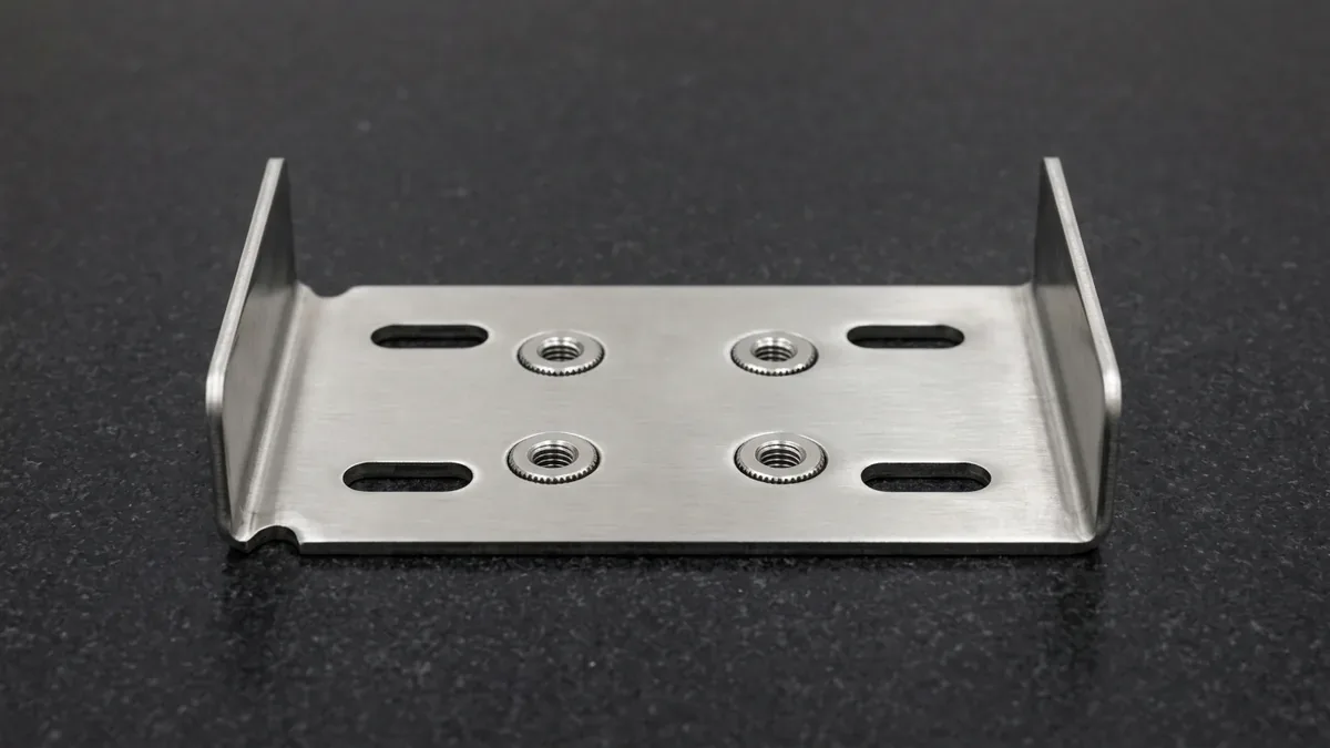
To provide high-strength, reusable load-bearing threads in thin sheet metal, our facility deploys automated hydraulic insertion presses to install self-clinching fasteners (commonly referenced by the trademark PEM). Unlike weld nuts that generate heat distortion and spatter, self-clinching operates entirely via cold plastic deformation:
- A pilot hole is cut into the flat blank via fiber laser or turret punch with strict diametral tolerance (+0.08 / −0.00 mm).
- The fastener is positioned in the hole over an engineered anvil, and a smooth hydraulic ram applies controlled squeeze pressure to the fastener head.
- The serrated clinching ring or knurled collar embeds into the sheet metal, forcing cold metal to flow plastically into an undercut annular groove around the fastener shank.
- The interlocked undercut locks the fastener against axial push-out, while the serrated ring provides high resistance to rotational torque-out.
Fastener Types & Critical Installation Clearances
Engineering drawings frequently incorporate several distinct families of clinch hardware:
- Self-Clinching Nuts (Type S / CLS / SP): Provide load-bearing internal threads flush with the reverse sheet face. Carbon steel nuts (Type S) are installed in cold-rolled steel; stainless steel nuts (Type CLS) in aluminum and steel; and precipitation-hardened nuts (Type SP) in 300-series stainless steel. (Rule of thumb: The clinching fastener must be significantly harder than the host sheet metal into which it is squeezed).
- Threaded Standoffs (Type BSO / SOS / SO): Blind or through-threaded spacers used to mount printed circuit boards (PCBs) and internal subassemblies at fixed stand-off heights (3.0 mm to 25.0 mm).
- Flush-Head Studs (Type FH / FHS): Externally threaded studs providing rigid male mounting points without protruding through the cosmetic outer face.
PEM DFM Rules for Hardware Placement
To prevent hardware displacement, chassis distortion, and tooling interference during press brake bending:
- Centerline-to-Edge Distance: Maintain a minimum distance from the fastener centerline to the nearest sheet edge of E ≥ 1.5 · Dhole. Installing too close to an unsupported edge causes the cold-flowing metal to bulge the part perimeter outward.
- Fastener-to-Bend Line Clearance: Fasteners must sit completely outside the bending deformation zone. Furthermore, sufficient clearance must remain for the wide insertion press anvil head: Dfastener-to-bend ≥ 3.0 · T + Rin + Ranvil. If hardware must sit closer to a flange, install the clinch hardware prior to the bending operation, ensuring the press brake punch clears the installed fastener body.
- Hardness Compatibility: Never attempt to install standard 304 stainless steel clinch nuts into 304 stainless steel sheet. The host sheet work-hardens instantly, preventing metal flow into the undercut and ruining the fastener. Stainless sheet requires specialized hardened Nitronic-60 or heat-treated 400-series clinch hardware.
7. Joining & Finishing: Laser Welding, Conversion Coatings & Powder Coating
Once sheet components are cut, punched, bent, and fitted with hardware, they transition to structural joining and surface protective finishing. Integrating design guidelines for secondary processing prevents cosmetic blemishes, corrosion traps, and post-assembly dimensional distortion.
Precision Sheet Joining: Robotic Laser Welding vs. TIG/MIG
Traditional manual TIG (GTAW) and MIG (GMAW) welding deposit significant thermal energy into the joint, creating broad Heat Affected Zones (HAZ). On thin sheet metal skins (0.8 mm to 1.5 mm), this thermal gradient induces severe residual stresses, causing cosmetic panels to warp, twist, and develop visible “oil-canning” buckles. Secondary operations require extensive manual grinding, sanding, and filling to restore a flat surface.
In contrast, our in-house robotic fiber laser welding systems utilize an ultra-focused high-density optical spot. Laser welding delivers high travel speeds (15 mm/s to 50 mm/s) with a microscopic HAZ, delivering deep seam penetration with virtually zero thermal distortion. Smooth, continuous laser welds on cosmetic corners require minimal surface blending prior to paint or powder coating.
Surface Pre-Treatment & Finishing Spectrum
To guarantee durability in harsh operating environments, sheet assemblies undergo rigorous industrial surface treatments:
- Chemical Conversion Coating (Alodine 1200S / SurTec 650): Applied to aluminum enclosures to provide RoHS-compliant corrosion protection while maintaining low surface electrical resistance, essential for electromagnetic shielding (EMI/RFI) and grounding continuity.
- Anodizing (MIL-A-8625 Type II / Type III): Sulfuric acid anodizing builds a dense, wear-resistant aluminum oxide ceramic layer (15 μm to 50 μm). Engineers must compensate for dimensional growth: anodizing penetrates approximately 50% into the substrate and builds 50% outward from the original surface.
- ASTM A967 Stainless Steel Passivation: Chemical immersion in citric or nitric acid baths dissolves free iron particles embedded from laser blanking or press brake tooling, restoring the passive chromium-oxide (Cr2O3) corrosion barrier.
- Electrostatic Powder Coating: Thermoset polyester or polyurethane powders electrostatically sprayed and heat-cured at 180°C–200°C deposit a tough 60 μm to 100 μm protective skin (RAL color-matched). DFM Notice: Always specify on technical drawings which threaded clinch holes, grounding pads, and precision slide surfaces must be silicone-masked prior to powder coating to prevent paint accumulation in threads and loss of electrical continuity.
8. Quality Assurance & Inspection: Mating Fit-Up, Checking Fixtures & Flange Gauging
Validating complex sheet metal enclosures against 3D CAD models requires specialized metrology techniques that separate rigid body geometric errors from natural sheet metal elasticity.
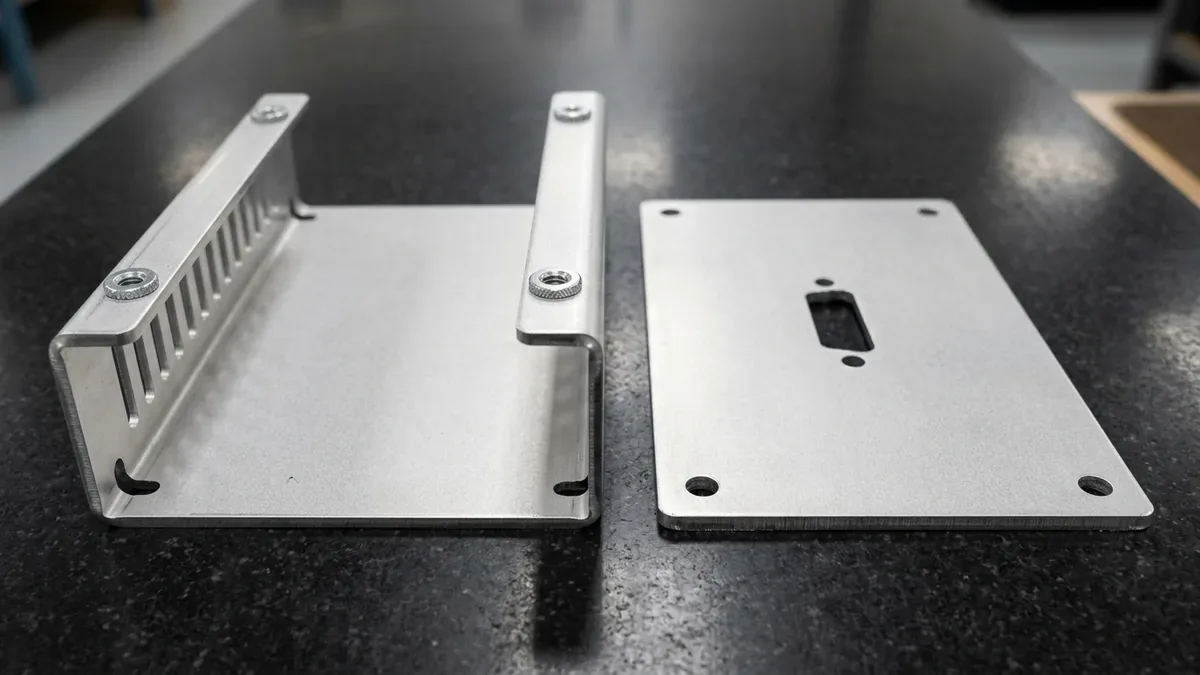
Mating Assembly Fit-Up & Dedicated Checking Fixtures
Because thin formed sheet metal parts exhibit natural elastic springback (±0.5° to ±1.0°) and subtle structural flex, authoritative sheet metal quality control relies on functional mating assembly fit-up, dedicated checking fixtures, and 2D optical flat-pattern verification rather than free-state point probing. Critical shop-floor inspection workflows include:
- Datum Reference Frame Alignment: Establishing primary Datum A across wide sheet mounting planes, followed by secondary and tertiary datum alignment through laser-pierced datum pin bores.
- True Position Verification of Hole Arrays: Verifying true position tolerances (Ø0.10 mm to Ø0.25 mm) for mating circuit board mounting patterns and connector cutouts across multiple formed planes.
- Flange Angularity, Radius & Mating Fit-Up: Calibrated digital angle protractors, radius gauges, precision 90° knife-edge squares, and full cover-to-chassis trial assembly verify that formed flanges and self-clinching fastener patterns mate seamlessly without hole misalignment.
2.5D Optical Vision Metrology & Free-State Inspection Rules
Because thin sheet metal parts are inherently compliant (non-rigid), free-state point probing is unsuitable for formed enclosures. Instead, inspecting the laser-cut flat blank on a 2D optical scanner before bending—and verifying the formed part on a dedicated checking fixture that replicates the actual bolted mating interface—guarantees true functional interchangeability.
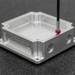
Our quality team applies ASME Y14.5M non-rigid part tolerancing, utilizing non-contact 2.5D optical vision measuring systems (VMS) to capture full-field surface mesh points in both free-state and simulated restrained mounting conditions. Color deviation heat maps instantly reveal springback curl, panel bow, and hole center drift across entire chassis assemblies.
9. Shop-Floor Defect Troubleshooting & Root-Cause Countermeasures
When sheet metal components fail dimensional inspection or visual quality standards during prototype trials, identifying the underlying mechanical root cause is vital for corrective DFM iteration. Below is our shop-floor troubleshooting matrix:
| Observed Defect | Root Cause Analysis | Shop-Floor Corrective Action | Engineering DFM Design Fix |
|---|---|---|---|
| Outer Bend Cracking / Splitting | Inside radius too sharp (R < 0.5T); bending parallel to rolling grain; work-hardened material. | Switch to punch with larger tip radius; increase V-die width; rotate blank orientation 45° to 90°. | Increase CAD inside bend radius to ≥ 3.0T–6.0T (for 6061-T6) or switch alloy to 5052-H32. |
| Hole Distortion / Ovalization | Hole edge positioned within the plastic bend deformation zone (< 2.5T + R). | Laser-cut hole as undersized pilot, ream after bending; or employ urethane bottom die tooling. | Relocate hole center ≥ 2.5T + R away from bend tangent line, or add an intermediate relief cutout. |
| Corner Tearing at Flange Edge | Absence of bend relief notches; shear stress tearing the transitional material. | Hand-dremel or saw-cut manual relief slit prior to press brake stroke. | Incorporate rectangular or teardrop relief notch: Depth ≥ R + T; Width ≥ T (min 1.5 mm). |
| Flange Angle Inconsistency (“Canoe Effect”) | Press brake upper ram and bed mechanical deflection under high tonnage across long beds. | Calibrate CNC dynamic bed crowning; shim die base; utilize segmented tooling. | Standardize bend radii across parts; widen V-die opening to reduce required forming tonnage. |
| PEM Hardware Push-Out / Spin-Out | Laser-pierced hole oversized; insufficient hydraulic squeeze tonnage; sheet harder than fastener. | Recalibrate laser kerf compensation; increase insertion press dwell force; inspect with GO/NO-GO pins. | Specify exact hole diameter (+0.08 / −0.00 mm); verify sheet hardness is below fastener max rating. |
| Cosmetic Scratches on Formed Panels | Friction between metal sheet and hardened steel V-die shoulders during ram descent. | Apply non-marking urethane protective film over V-die shoulders; clean die surfaces regularly. | Specify laser protective PVC film on raw sheet stock; order pre-anodized or brushed finishes. |
10. Technical Engineering FAQ
Bend Allowance (BA) is the actual arc length of material consumed along the shifted neutral axis between the two tangent lines of a bend. Bend Deduction (BD) is the difference between the sum of the two outside flange leg lengths and the total flat blank length (BD = 2 · OSSB − BA). While BA calculates the developed curve length directly, BD allows machine operators and CAD algorithms to determine the exact flat cutout length by simply taking the external finished dimensions and subtracting the deduction for each bend.
Aluminum 5052-H32 contains 2.5% magnesium and is work-hardened, giving it superior elongation (12% to 18%) and exceptional ductility. It can easily bend to a tight inside radius equal to its thickness (R = 1.0t) without cracking. Conversely, 6061-T6 is an artificially aged, precipitation-hardened structural alloy with high yield strength (276 MPa) but lower elongation (8% to 10%). Bending 6061-T6 to tight radii causes tensile fracture along the outer grain boundary unless a wide radius (R ≥ 3.0t to 6.0t) or specialized O-temper annealing is applied.
High-pressure nitrogen (18 to 25 bar) acts as an inert shielding gas that mechanically blows molten metal out of the cut kerf without chemical reaction, leaving a 100% clean, bright, oxidation-free edge. This edge is immediately ready for welding, chemical conversion, or powder coating. Oxygen assist gas (0.5 to 3.0 bar) creates an exothermic combustion reaction that assists in cutting thick carbon steel plate but leaves a thin, brittle iron-oxide scale. If not chemically or mechanically stripped before powder coating, this oxide layer causes paint delamination under salt spray testing.
Hole distortion occurs when a cutout is located within the plastic strain zone surrounding the bend axis. As the punch draws the sheet into the V-die, material near the bend line undergoes severe elongation, stretching circular holes into distorted ovals. To prevent ovalization, the edge of any hole, slot, or hardware cutout must be located at a distance of at least 2.5 times material thickness plus the inside bend radius (Distance ≥ 2.5T + R) from the bend tangent line.
Direct thread tapping in sheet metal thinner than 2.5 mm provides fewer than three full thread engagements, leading to thread stripping under low torque. Welded nuts introduce thermal distortion, sheet warping, and weld spatter that ruin cosmetic surfaces. Self-clinching PEM fasteners cold-flow into laser-pierced holes under controlled hydraulic pressure, generating high pull-out and torque-out resistance with a completely flush rear face, preserving thin sheet integrity and corrosion-resistant finishes.
Engineer Precision Custom Sheet Metal Enclosures & Brackets
Eliminate bend springback, hole distortion, and assembly interference before cutting metal. Upload your 3D CAD files (STEP/IGES) and 2D flat-pattern drawings for a dedicated sheet metal DFM review and custom production quotation.
Upload CAD Files for Sheet Metal DFM & Quote