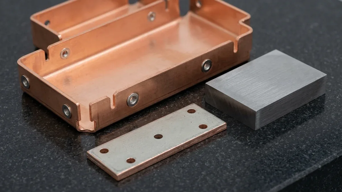
Designing high-current busbars, thermal spreaders, and RF shielding enclosures demands superior electrical and thermal conductivity. Therefore, deploying specialized copper sheet metal fabrication allows engineering teams to achieve maximum electrical efficiency. Copper sheet metal combines exceptional ductility with unmatched thermal dissipation across demanding operating environments. Specifically, custom copper stampings and bent busbars dominate electric vehicle battery systems and power inverters.
However, copper’s high optical reflectivity and softness introduce unique challenges during laser profiling and press brake forming. Uncompensated laser beams risk optical back-reflection damage, while improper bend tooling creates surface scratching or edge orange-peeling. Understanding alloy tempers, minimum bend radiuses, and surface plating treatments ensures flawless manufacturing execution. In this comprehensive guide, we evaluate copper alloys, profiling technologies, and essential DFM rules.
- Core Focus & DFM Scope: Actionable shop-floor engineering guidelines for Copper Sheet Metal, covering material selection, geometric tolerancing, and defect prevention.
- Cutting & Forming Precision: Fiber laser and abrasive waterjet profiles hold ±0.05 to ±0.10 mm (±0.002″ to ±0.004″); CNC press brake flanges hold ±0.15 mm (±0.006″) and ±0.5° angular accuracy per DIN 6935.
- Edge Quality & Material Gauge: Burr-free nitrogen-assisted laser edges and zero-HAZ cold waterjet kerfs across 0.5 mm (24 Ga) to 50 mm (2.0″) gauges in aluminum, stainless steel, carbon steel, and copper.
- K-Factor & Flat-Pattern DFM: Empirical bend deduction calibration (K = 0.33–0.44) with grain-direction stress relief to prevent flange cracking and springback drift.
- Ex-Factory Turnaround: 4 to 8 business days for laser/waterjet cut and bent sheet metal prototypes; 7 to 12 business days with powder coating, anodizing, or PEM hardware insertion (excluding 3–5 days air transit).
1. Copper Sheet Alloys: C11000 ETP vs C10100 OFHC
Selecting the proper raw copper grade dictates electrical performance and fabrication ductility. Commercial electrolytic tough pitch copper C11000 represents the most common alloy for sheet metal fabrications. C11000 delivers one hundred percent electrical conductivity and excellent room-temperature cold workability. However, C11000 contains microscopic cuprous oxide particles that cause hydrogen embrittlement during high-temperature brazing or welding.
Conversely, oxygen-free electronic copper C10100 is refined in oxygen-free environments to eliminate oxide impurities. Consequently, C10100 can be brazed, welded, and operated in vacuum electronics without risking brittle failure. In shop-floor practice, temper designation determines sheet stiffness and forming limits. Soft annealed copper bends easily around tight pins, whereas half-hard tempers resist springback during stamping.
2. Profiling Blanking: Fiber Laser vs Abrasive Waterjet Cutting
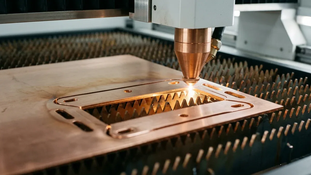
Precision blanking represents the critical initial step in copper sheet metal processing. Historically, CO2 lasers struggled to cut copper because the metal reflected over ninety-eight percent of infrared light. In contrast, modern high-power fiber lasers operate at shorter wavelengths where copper absorption increases significantly. Furthermore, advanced laser cutting heads incorporate optical back-reflection sensors that protect resonators from stray reflected rays.
Alternatively, abrasive waterjet cutting provides a cold erosion method that eliminates back-reflection risks entirely. Waterjets cut thick copper busbar plate up to fifty millimeters cleanly without generating burrs or localized heat. Through our precision sheet metal fabrication services, we deploy lasers for thin sheets and waterjets for plates. Consequently, cut blanks feature perfectly square edges with zero thermal dross.
The comparative engineering parameters across copper sheet alloys are summarized in the table below.
| Copper Alloy Grade | Temper Condition | Tensile Strength (MPa) | Yield Strength (MPa) | Electrical Conductivity (% IACS) |
|---|---|---|---|---|
| C11000 Electrolytic Tough Pitch | O60 (Soft Annealed) | 220 to 260 | 65 to 90 | 100% to 101% |
| C11000 Electrolytic Tough Pitch | H02 (Half-Hard) | 290 to 340 | 240 to 280 | 98% to 100% |
| C10100 Oxygen-Free Electronic | O60 (Soft Annealed) | 220 to 250 | 60 to 85 | 101% to 102% |
| C10200 Oxygen-Free Copper | H04 (Hard Temper) | 330 to 390 | 300 to 350 | 100% to 101% |
| C12200 Phosphorus-Deoxidized | H02 (Half-Hard) | 270 to 330 | 220 to 260 | 85% to 90% |
3. Press Brake Bending Dynamics and Springback Control
Forming precise angles in copper sheet metal requires strict adherence to minimum bend radius guidelines. Because copper strain-hardens rapidly along outer tensile bend fibers, sharp radii cause micro-cracking and cosmetic orange-peel textures. Engineers mandate an inside bend radius equal to at least 1.0 times material thickness for soft tempers. For half-hard sheets, the minimum inside bend radius should equal 1.5 to 2.0 times thickness.
Furthermore, press brake tooling must utilize protective urethane film dies to prevent metal galling. Bare hardened tool steel punches can leave deep cosmetic impressions on soft copper surfaces. In addition, CNC press brakes compensate automatically for minor elastic springback variations across sheet coils. From an engineering perspective, bent busbars achieve angular accuracy within ±0.5 degrees across every production flange.
4. Secondary Surface Finishing and Plating Protection
Untreated copper sheet metal oxidizes rapidly when exposed to atmospheric humidity and airborne contaminants. Therefore, secondary surface treatments are mandatory to protect electrical contact surfaces and ensure joint solderability. High-voltage battery busbars frequently receive electroplated tin coatings. Tin coatings prevent atmospheric oxidation and lubricate bolted terminal connections under continuous thermal vibration.
In addition, critical electronics busbars utilize bright nickel plating topped with hard gold flash. Through our specialized surface finishing processes, AS Prototypes applies electroplated tin, nickel, silver, and chemical passivations. Non-destructive XRF spectrometers measure plating thicknesses accurately across every production batch. Consequently, our custom fabricated copper components provide dependable field service across decades of operation.
The operational guidelines across primary copper sheet metal blanking methods are detailed below.
| Blanking Technology | Kerf Width (mm) | Edge Heat-Affected Zone | Best Sheet Thickness Range | Production Volume Fit |
|---|---|---|---|---|
| High-Power CNC Fiber Laser | 0.15 to 0.35 mm | Minimal localized HAZ (<0.2 mm) | 0.5 mm to 6.0 mm sheets | Prototype to medium/high volume |
| CNC Abrasive Waterjet | 0.75 to 1.10 mm | Zero Heat-Affected Zone (cold cut) | 6.0 mm to 50.0+ mm plates | Heavy busbars, low-to-medium volume |
| CNC Mechanical Turret Punching | Tool-defined slug | Zero HAZ (mechanical shear) | 0.8 mm to 3.2 mm sheets | High volume repetitive perforations |
| Progressive Stamping Dies | Punch clearance | Zero HAZ (high-speed shear) | 0.2 mm to 4.0 mm coils | Mass production (>50,000 parts) |
Why Do Copper Sheet Metal Parts Develop Edge Taper, Thermal Distortion, or Bend Cracking?
Achieving repeatable dimensional accuracy in Copper Sheet Metal requires controlling kerf width offset, heat-affected zone (HAZ) recrystallization, and minimum inside bend radii relative to sheet grain direction. While precision CNC profiling holds ±0.05 to ±0.10 mm (±0.002″ to ±0.004″), placing holes closer than 1.5× material thickness to a bend line or cutting narrow bridges under 1.0× thickness triggers distortion.
Shop-Floor Quantitative Derivation: Flat-Pattern Bend Allowance (BA) & Kerf Offset
In our sheet metal and CNC profiling facility, translating a 3D enclosure or bracket into an accurate 2D flat pattern for Copper Sheet Metal requires exact Bend Allowance (BA) and Bend Deduction (BD) math per DIN 6935. For a 90° bend (θ = π/2 rad) in t = 2.0 mm (14 Ga / 0.078″) material with an inside bend radius R = 2.0 mm (0.078″) and an empirical neutral-axis K-factor of K = 0.38:
BA = θ × (R + K × t) = 1.5708 × (2.0 + 0.38 × 2.0) = 4.335 mm (0.1707″)
With outside setback OSSB = tan(45°) × (R + t) = 4.000 mm, the Bend Deduction is BD = 2 × OSSB − BA = 8.000 − 4.335 = 3.665 mm (0.1443″) per 90° bend. Simultaneously, CNC CAM nesting shifts the cutting path outward by exactly half the beam/stream kerf width (typically rkerf = 0.10 mm / 0.004″ for fiber laser or 0.45 mm / 0.018″ for abrasive waterjet) so the finished part boundary lands at nominal CAD dimension.
Step-by-Step Shop-Floor Execution & Quality Protocol
To bridge CAD intent with repeatable shop-floor delivery, our engineering team enforces a four-stage execution workflow across every prototype and low-volume production batch:
- Step 1: Flat-Pattern Unfolding & Grain-Direction Nesting: Unfold 3D CAD models using material-calibrated K-factors (0.33–0.44) and orient high-stress press-brake bend axes perpendicular to the rolling grain direction of the sheet coil.
- Step 2: Pierce Lead-In & Kerf Offset Programming: Place piercing lead-ins inside scrap cutouts rather than on finished part contours, applying high-pressure nitrogen assist gas or dynamic tilt-head taper compensation.
- Step 3: Vibratory Deburring & Edge Conditioning: Pass profiled blanks through wide-belt orbital deburring and brush-grinding stages to remove micro-dross and establish safe R 0.15 mm (0.006″) broken edges prior to forming.
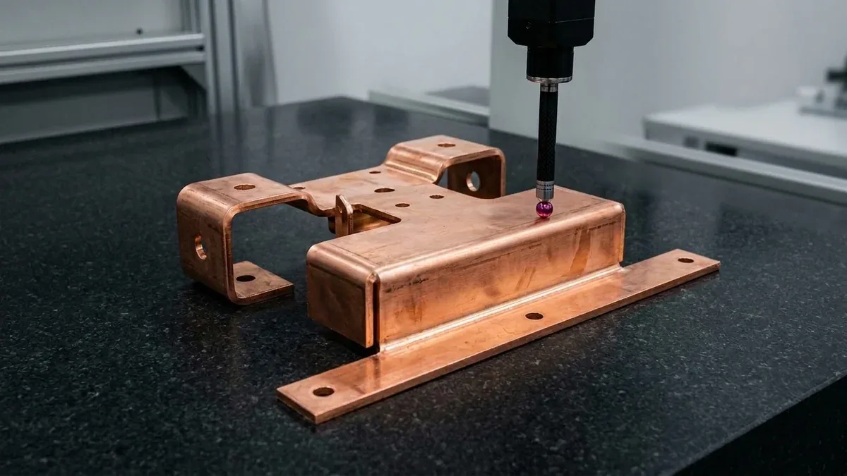
- Step 4: Optical Angle Controlled Bending & Hardware Insertion: Form flanges on multi-axis CNC press brakes with real-time laser springback compensation (±0.5°), install PEM self-clinching fasteners, and verify geometry on our inspection table.
Shop-Floor Defect Troubleshooting & Corrective Action Matrix
When evaluating part geometry during pre-production DFM review, our manufacturing engineers screen for the following failure modes and apply proven corrective controls:
| Defect / Symptom | Physical Root Cause | Shop-Floor Corrective Action | Recommended DFM Spec Limit |
|---|---|---|---|
| Outer Bend Radius Cracking | Inside bend radius too sharp (R < 0.8t) or bend line oriented parallel to cold-rolled grain direction | Increase inside punch radius to R ≥ 1.0t–1.5t (or anneal temper) and re-nest flat blanks 90° across the mill rolling grain. | Min bend radius R ≥ 1.0t |
| Hole Ovality Near Bend Lines | Cutouts positioned within the plastic deformation zone (< 2t + R from inside bend tangent) | Relocate holes to a minimum distance D ≥ 2.0t + R from the bend line, or add a 1.0t wide bend-relief slot. | Hole-to-bend D ≥ 2t + R |
| Bottom Edge Dross / Slag Burrs | Suboptimal assist gas pressure, nozzle standoff drift, or focal point misalignment | Switch from oxygen to 18–22 bar high-purity nitrogen assist gas and recalibrate capacitive height sensing. | Burr height ≤ 0.03 mm |
| V-Shaped Kerf Edge Taper | Jet stream divergence or beam defocusing through thick plate sections (> 15 mm / 0.60″) | Engage 5-axis dynamic taper-tilt compensation head (±0.05 mm perpendicularity) or post-ream precision H7 bores on a CNC VMC. | Squareness ≤ 0.05 mm |
Engineering Trade-Offs: When NOT to Over-Specify
When to Avoid This Process (Engineering Limitations): Sheet metal profiling and bending cannot natively produce variable-thickness 3D pockets, O-ring seal grooves, or high-stiffness integral bosses without secondary welding or stacked laminations. When an enclosure requires EMI shielding gasket channels, blind threaded bosses, or flatness better than 0.05 mm (0.002″) across mounting pads, hogging the housing from solid 6061-T6 billet on a 3-axis or 4-axis CNC milling center provides superior structural rigidity and hermeticity.
🔗 Related Sheet Metal & Secondary CNC Fabrication Guides:
When specifying Copper Sheet Metal for structural chassis and enclosures, controlling bend springback, edge burr condition, and protective coatings prevents assembly interference. Consult our Precision Sheet Metal Forming: 7 Engineering Best Practices, review Progressive Stamping Die & Forming DFM Rules, and compare corrosion protection in our Complete Metal Surface Finishing Guide.
Copper possesses extremely high thermal conductivity and optical reflectivity. Standard CO2 lasers risk optical back-reflection damage. Modern fiber lasers operate at shorter wavelengths that copper absorbs much more efficiently. At AS Prototypes, our engineering team validates these parameters against ISO 2768-mK general tolerances (with critical mating features held to ±0.010 mm / ±0.0004″) and provides 24-hour DFM feedback.
For soft annealed copper, the minimum inside bend radius is 1.0 times sheet thickness. For half-hard or hard tempers, engineers specify an inside radius of 1.5 to 2.0 times thickness to prevent cracking. At AS Prototypes, our engineering team validates these parameters against ISO 2768-mK general tolerances (with critical mating features held to ±0.010 mm / ±0.0004″) and provides 24-hour DFM feedback.
Bare copper tarnishes quickly in ambient air, forming an insulating oxide film that increases electrical contact resistance. Electroplated tin or nickel prevents oxidation, facilitates soldering, and ensures low-resistance joints. At AS Prototypes, our engineering team validates these parameters against ISO 2768-mK general tolerances (with critical mating features held to ±0.010 mm / ±0.0004″) and provides 24-hour DFM feedback.