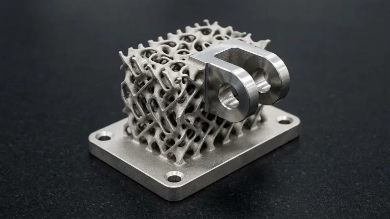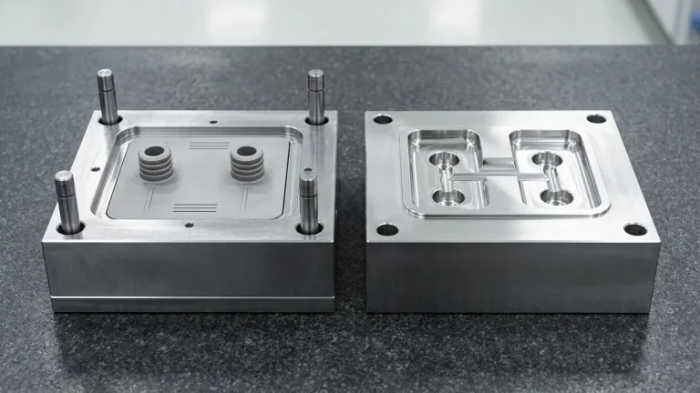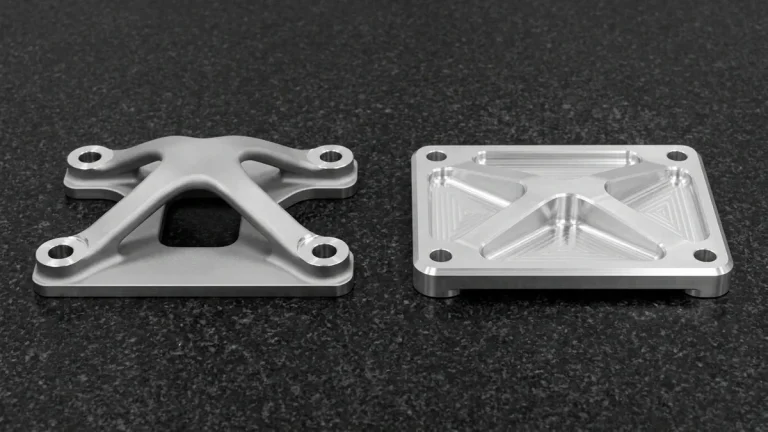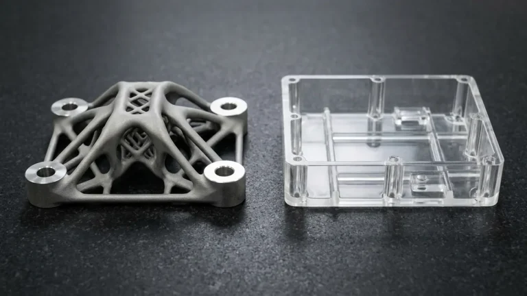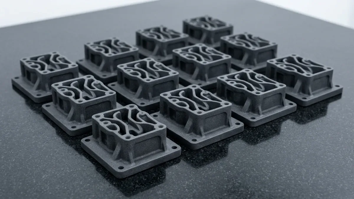
For decades, design engineers viewed additive manufacturing exclusively through the lens of rapid prototyping: an invaluable technique for verifying physical ergonomics and checking mechanical clearances before committing to permanent steel injection molds or stamping dies. Once production volumes scaled past several hundred pieces, hard tooling inevitably took over.
Today, technological leaps in industrial powder-bed fusion, high-speed thermal fusing agents, and automated depowdering systems have rewritten manufacturing economics. Hardware brands across aerospace, robotics, consumer electronics, and medical technology now deploy 3D printing for mass production, producing tens of thousands of end-use, mission-critical components without ever cutting a single mold cavity.
At AS Prototypes, our additive production center operates large-scale MJF, SLS, and DMLS printer farms supported by multi-axis CNC milling centers and automated post-finishing lines. In this comprehensive guide, we examine unit cost break-even mechanics, 3D volumetric nesting physics, mechanical anisotropy mitigation, automated surface vapor smoothing, and proven design for additive manufacturing (DFAM) rules for high-volume serial production.
From our production floor: the parts that cause trouble in serial additive runs are rarely the exotic ones. They are the ordinary housings, clips, and brackets that were designed for a prototype, then released for 5,000 pieces without a second look. We review every serial order against the lessons below before a single build file is nested.
- 1. Economic Mechanics: Break-Even Modeling vs Injection Molding & CNC
- 2. Volumetric Packing Density and 3D Nesting Kinetics
- 3. Mechanical Anisotropy and Build Plane Optimization
- 4. Industrial Additive Systems: Technical Comparison Matrix
- 5. Direct Metal Additive (DMLS / LPBF) in Serial Production
- 6. Automated Post-Processing and Surface Vapor Smoothing
- 7. Statistical Process Control (SPC) and Lot Traceability
- 8. Design for Additive Mass Production (DFAM) Engineering Rules
- 9. Production Workflow: From CAD Release to Lot Shipment
- 10. Material Selection for Serial Polymer Parts
- 11. Surface Finish Options Compared
- 12. Tolerance, Shrinkage Compensation and Build Orientation
- 13. Troubleshooting Serial Production Defects
- 14. When Should You Not Use 3D Printing for Mass Production?
- 15. Lead Time and RFQ Checklist
- 16. Technical Engineering FAQ
1. Economic Mechanics: Break-Even Modeling vs Injection Molding & CNC
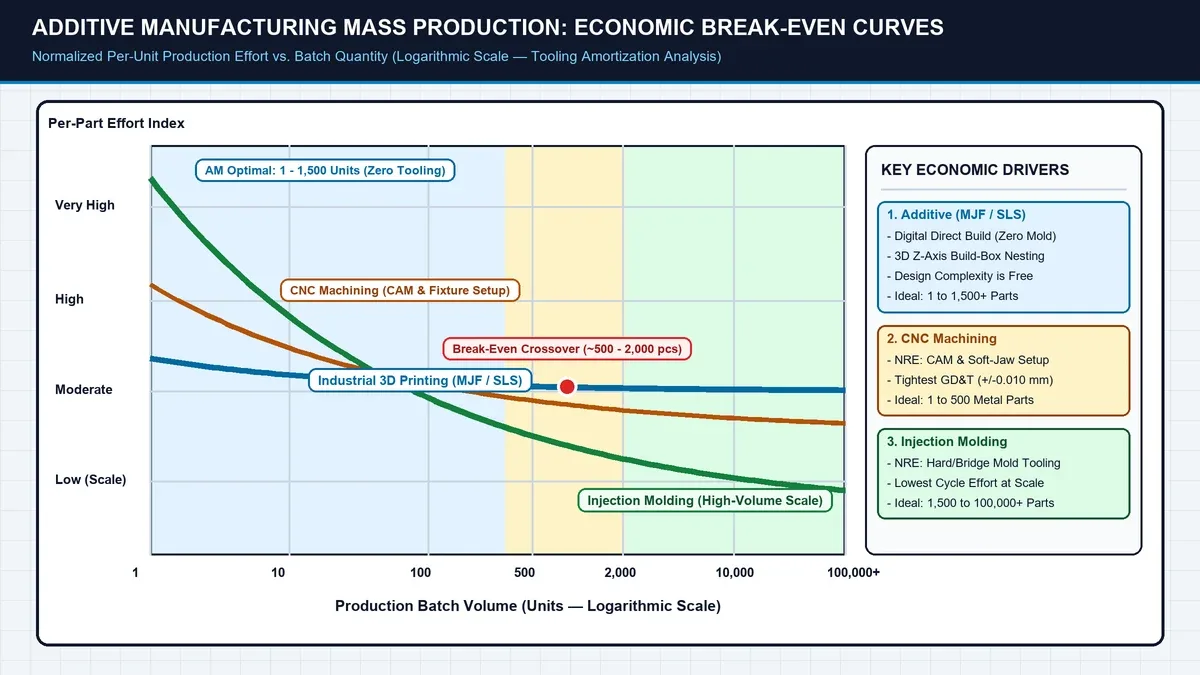
Determining whether to deploy additive manufacturing or conventional injection tooling for volume production is an engineering optimization problem balancing upfront non-recurring engineering (NRE) tooling costs, lead times, inventory holding risks, and piece-part unit costs. For a process-level comparison, read our CNC machining vs 3D printing guide, or review our MJF 3D printing service for nylon PA12 production capacity.
1.1 Total Production Cost Formulations
The total project manufacturing cost for an additive production run (Cadditive) across volume N can be expressed as:
Where Cpowder is powder material cost per cm3, Vpart is solid part volume, ηyield is powder reusability yield, Cmachine-hour is printer operational amortization rate, tbuild is total build cake print duration, nnesting is total parts packed in the chamber, and Cpost-finishing is automated bead blasting, vapor smoothing, and dyeing costs.
Conversely, conventional injection molding cost (Cmolding) incorporates fixed tooling procurement:
Where Ctooling is initial mold design, CNC roughing, wire EDM, and benching cost (a substantial, quote-dependent investment for multi-cavity hardened H13/S136 steel tools), and the second term represents variable production expenses.
1.2 Mathematical Derivation of the Break-Even Volume
Setting Cadditive(Nbreak) = Cmolding(Nbreak) yields the critical break-even production quantity (Nbreak):
Because additive manufacturing incurs zero upfront tooling costs (Ctooling = 0), the per-part cost curve remains virtually flat from part 1 to part 10,000. For small-to-medium parts (such as electronic connector housings, drone arm brackets, and robotic sensor mounts), the break-even volume typically lands between 3,000 and 20,000 units. If a design features complex undercuts, internal channels, or thin ribs that would require expensive side-action sliders or lifters in an injection tool, the break-even threshold expands beyond 30,000 units.
| Production Volume | MJF Nylon PA12 (Additive) | CNC Machined Billet | Injection Molding (H13) | Optimal Production Strategy |
|---|---|---|---|---|
| 50 Units (Prototype Batch) | Medium Unit Cost (Direct Additive Build) | High Unit Cost (Multi-Setup Machining Time) | Unfavorable (High Upfront Tooling Amortization) | Additive Manufacturing (Fastest turnaround) |
| 500 Units (Pilot Launch) | Economical Unit Cost (Full Build Volume Nesting) | Moderate Unit Cost (Batch Fixtured CNC Runs) | Transition Zone (Bridge Tooling Cost Amortization) | Additive Manufacturing (Lowest total cash spend) |
| 5,000 Units (Medium Batch) | Steady Unit Cost (Continuous Machine Capacity) | Moderate Unit Cost (Dedicated Tombstone Fixtures) | Highly Cost-Effective (Tooling Amortized) | Break-even crossover region (Evaluate lead time) |
| 50,000 Units (Mass Scale) | Steady Linear Cost (Additive Capacity Bound) | Moderate Linear Cost (Palletized FMC Cells) | Lowest Unit Cost (High-Volume Automated Injection) | Injection Molding (Scale amortizes steel tool) |
2. Volumetric Packing Density and 3D Nesting Kinetics
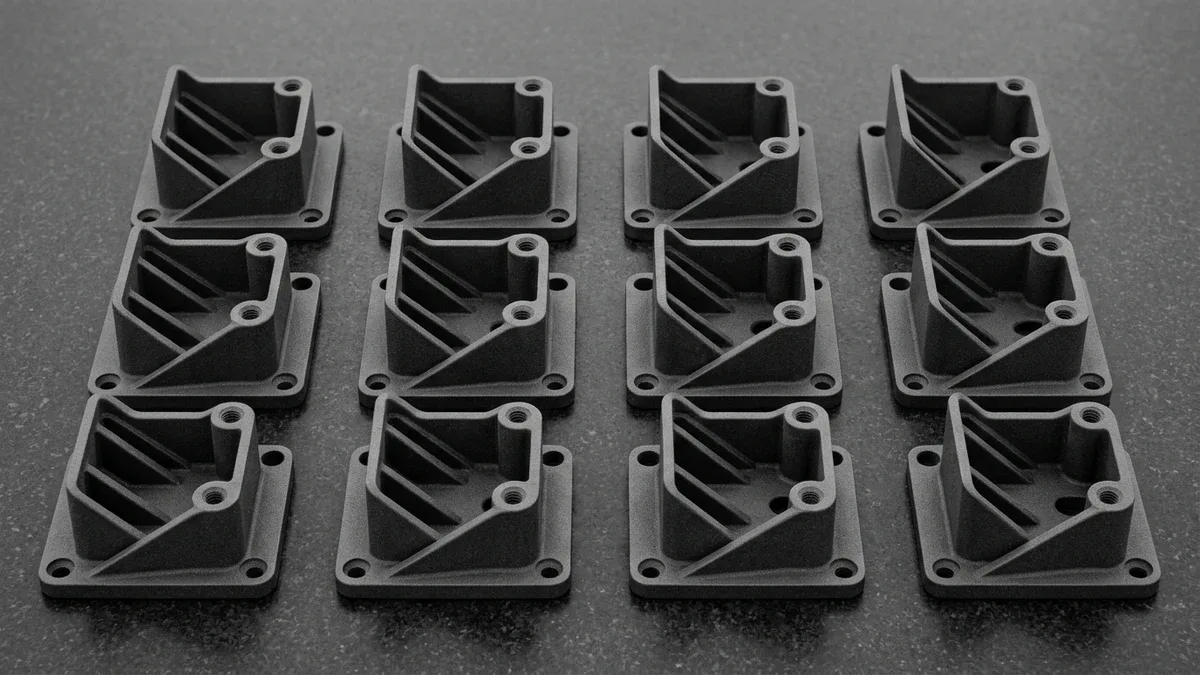
In powder-bed additive manufacturing technologies such as Multi Jet Fusion (MJF) and Selective Laser Sintering (SLS), parts do not require rigid build supports connected to a base plate. Instead, components are suspended freely in unsintered polymer powder, allowing technicians to pack parts in true 3D spatial arrangements across X, Y, and Z axes.
Because total printer cycle time is dominated by Z-axis layer recoating and fusing passes (approx. 10 to 12 seconds per 80-micron layer), printing a build cake packed with 1,000 parts takes nearly the same time as printing one with only 200 parts. The critical metric governing additive mass production unit cost is volumetric packing density (ηpacking):
In standard prototyping builds, packing densities rarely exceed 4% to 6%. At AS Prototypes, our nesting engineers deploy multi-threaded algorithmic 3D nesting software that interlocks organic geometries, achieving packing densities of 10% to 15%. Boosting packing density from 6% to 12% effectively doubles the output per build cycle, slashing machine amortization costs per part by over 50%.
3. Mechanical Anisotropy and Build Plane Optimization
A common concern among mechanical engineers evaluating additive manufacturing for mass production is directional strength variation (anisotropy) caused by layer-by-layer deposition.
While filament-based Fused Deposition Modeling (FDM) printing exhibits severe interlaminar weakness (Z-strength often dropping 40% to 60%), powder-bed fusion delivers exceptional quasi-isotropic properties due to high chamber thermal bias and complete polymer melt consolidation. In Multi Jet Fusion (MJF) PA12, the mechanical anisotropy ratio (ηanisotropy) is tightly controlled:
The vertical Z-axis retains approximately 88% to 92% of the ultimate tensile strength measured in the horizontal XY plane. However, elongation at break exhibits greater sensitivity, dropping from approx. 18% in XY down to 10% to 12% along the Z build axis.
To eliminate field failure risks during mass production, our CAM engineers execute stress tensor alignment during build preparation: primary tensile, bending, and torsional load paths are systematically oriented in the XY build plane (or tilted at a 45-degree compound angle to optimize packing volume while balancing multiaxial shear stresses).
4. Industrial Additive Systems: Technical Comparison Matrix
Selecting the optimal additive modality for volume production depends on whether components are polymer or metallic, structural or cosmetic, and rigid or elastomeric.
| Additive Technology | Core Materials | Layer Thickness | Standard Tolerance | Max Packing Density | Serial Production Niche |
|---|---|---|---|---|---|
| Multi Jet Fusion (MJF) | Nylon PA12, PA11, TPU 88A | 80 μm (0.08 mm) | ±0.2 mm per 100 mm | 12% to 16% | 500 to 50,000+ units, functional consumer & robotics |
| Selective Laser Sintering (SLS) | PA12, Glass-Filled Nylon (PA-GF) | 100 to 120 μm | ±0.2 mm per 100 mm | 8% to 12% | 100 to 10,000 units, stiff enclosures & jigs |
| Direct Metal Laser Sintering (DMLS) | Ti-6Al-4V, 316L, Inconel 718, AlSi10Mg | 30 to 60 μm | ±0.10 mm or ±0.1% | Plate limited (Supports req.) | 50 to 2,000 units, aerospace fluidics & implants |
| Stereolithography (SLA) | ABS-like, Clear, High-Temp Ceramic | 50 to 100 μm | ±0.2 mm per 100 mm | Plate limited (Supports req.) | 10 to 500 units, optical lenses & master patterns |
5. Direct Metal Additive (DMLS / LPBF) in Serial Production
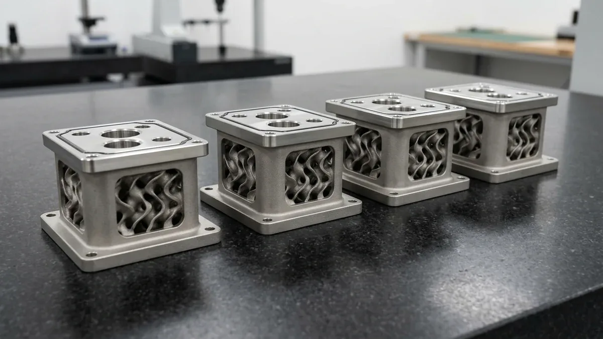
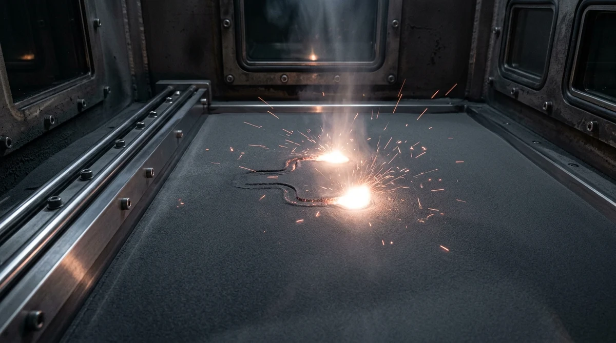
While polymer additive manufacturing dominates electronic enclosures and brackets, metal Laser Powder Bed Fusion (LPBF / DMLS) commands serial production in aerospace, space propulsion, and surgical medical hardware.
In high-pressure fluid manifolds and rocket engine fuel injectors, metal 3D printing enables part consolidation: combining complex assemblies of 15 to 30 CNC-machined billets, brazed joints, and O-ring seals into a single monolithic titanium or Inconel component. This eliminates leak paths, cuts weight by 40% via internal gyroid lattices, and delivers 99.8% metallurgical density.
To ensure repeatable flight-grade mechanical integrity, every serial DMLS production run at AS Prototypes adheres to a strict post-thermal protocol:
- High-Temperature Vacuum Stress Relief: Because rapid laser melting introduces thermal gradients exceeding 106 K/s, parts undergo vacuum stress relief annealing at 850°C (for Ti-6Al-4V) or 1,060°C (for Inconel 718) while still anchored to the build plate. This relieves over 95% of internal residual stress before wire EDM platform cut-off, preventing component warping.
- Hot Isostatic Pressing (HIP): For fatigue-critical aerospace hardware, parts undergo HIP processing at 920°C and 100 MPa argon pressure, closing micro-pores and ensuring 100% internal metallurgical density.
- Secondary CNC Datum Machining: Precision 3/4-axis VMCs finish critical O-ring seal grooves, bearing journals, and threaded ports to ±0.010 mm tolerances. Review our specialized metal printing services for full technical alloy datasheets.
6. Automated Post-Processing and Surface Vapor Smoothing
As-printed powder-bed parts exhibit a natural matte, micro-textured surface with a roughness of Ra 6.0 μm to 10.0 μm. While acceptable for hidden internal chassis components, exposed consumer goods and fluid-handling parts demand refined cosmetic finishes.
In mass production workflows, manual sanding is prohibitively expensive. Instead, our facility integrates a fully automated, scalable post-processing chain:
- Automated Rotary Blasting: Build cakes are transferred to automated de-coring systems where oscillating air knives and tumbling chambers extract 98% of unfused powder without damaging fine features.
- Chemical Vapor Smoothing: Components are loaded into a sealed industrial vacuum chamber. A specialized solvent vapor is introduced at controlled temperature and pressure, condensing uniformly onto the polymer surface. The solvent liquifies the microscopic peaks of the surface roughness, causing the outer 10-micron polymer layer to reflow under surface tension before the solvent is fully evacuated and recovered.
- Benefits of Vapor Smoothing:
- Substantially lowers surface roughness from approx. Ra 8.0 μm, yielding a smoother, more uniform satin finish; the final value depends on geometry and cycle settings.
- Contracts open surface micro-pores, markedly improving resistance to moisture, oils, and dirt pickup.
- Increases elongation at break and impact toughness by eliminating surface micro-notches that act as crack initiation sites.
- Automated Dyeing & Surface Sealing: Parts are processed in automated high-temperature deep-dye tanks to achieve consistent, deep-penetrating UV-stable black coloration.
6.1 How Does AMT Polishing Change PA12 Parts?
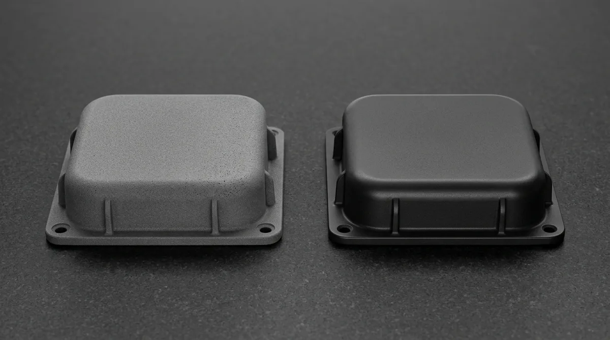
AMT polishing is an automated vapor-smoothing process for thermoplastic powder-bed parts such as MJF and SLS nylon PA12. A controlled solvent vapor softens only the outermost skin of each part inside a sealed chamber, so surface peaks soften and open micro-pores contract, without any abrasive media, sanding, or manual contact. It does not erase the powder grain completely; it makes the surface smoother and more uniform.
On our finishing line, raw PA12 housings leave the depowdering station with a grainy, matte grey surface of roughly Ra 6 to 10 μm (0.24 to 0.39 mil). After the AMT cycle, the same geometry shows a smoother, more uniform satin skin with contracted surface pores, a fine residual grain, crisp rib edges, a deeper uniform black tone once dyed, and noticeably better resistance to moisture, oils, and dirt pickup.
Every AMT cycle runs four controlled stages:
- Condition the loaded parts to a stable chamber temperature so the skin reacts evenly across the whole rack.
- Introduce the solvent vapor, which condenses on the surface and reflows the outer polymer layer.
- Cure the parts so the reflowed skin re-solidifies into a sealed, uniform surface.
- Dry the batch until residual solvent is fully evacuated, then release it to dyeing or inspection.
Published data helps set expectations. AMT specifies a dimensional change of 0.4% or less for PA12, and its PostPro SF100 cycle runs about 1.5 to 2 hours across the four stages. Independent measurements on powder-bed nylon report typical roughness falling from roughly Ra 6.4 μm (250 μin) to about 1.6 to 2.5 μm (64 to 100 μin), and one study recorded an average reduction near 84%. Results vary with geometry and settings, so treat them as ranges, not guarantees. Because 0.4% equals 0.4 mm on a 100 mm (3.94 in) feature, the upper bound exceeds our general ±0.2 mm per 100 mm tolerance. We therefore apply a CAD offset based on first-article data and verify critical features via 2.5D optical vision metrology (VMS), calibrated Go/No-Go pin gauges, and mating assembly fit-up checks before releasing a lot. Treat AMT polishing as a cosmetic and sealing step, and keep functional fits (snap-fits, press-fit bosses, bearing seats) on the post-process drawing so they are inspected after smoothing.
| Symptom | Root Cause | Corrective Action | Recommended Application |
|---|---|---|---|
| Softened ribs or rounded sharp edges | Vapor exposure too long for thin features | Shorten the exposure stage and keep ribs at 1.5 mm (0.06 in) or thicker | Enclosures with fine snap-fit ribs |
| Uneven gloss across one batch | Parts racked too close, blocking vapor flow | Re-rack with open spacing and consistent orientation | Serial lots of identical housings |
| Tacky or sticky surface after the cycle | Incomplete cure or drying stage | Extend the cure and dry stages before dyeing or packing | Dyed black consumer and robotics parts |
When not to use it: AMT polishing only works on thermoplastics such as PA12 and TPU, so metal DMLS parts need blasting or secondary CNC finishing instead. It also softens crisp micro-features and fine text, so very small details should be tested on a sample before a full lot is committed.
6.2 Field Case: Reducing PA12 Particle Shedding in Semiconductor Equipment
An Israeli semiconductor equipment manufacturer came to us with a persistent problem: PA12 parts used near dust-sensitive optical and wafer-handling processes kept shedding fine dust. The cause is structural. As-printed powder-bed nylon has an open, grainy skin, roughly Ra 6 to 10 μm, where loosely bonded powder particles sit in surface pores and release under handling, vibration, or airflow.
We recommended AMT polishing. By contracting those open pores and consolidating the outer skin, the process holds surface particles in place. The customer reported that the shedding problem was greatly reduced, and they have been very satisfied with the result.
We do not present this as a formal particulate-control classification claim. AMT polishing addresses surface porosity, not the inherent particle generation or outgassing behavior of the material, so parts for controlled environments should still be cleaned, handled with lint-free gloves, and validated with the customer’s own particle-count method.
7. Statistical Process Control (SPC) and Lot Traceability
Transitioning from one-off prototypes to serial manufacturing requires rigorous statistical quality assurance. In high-volume powder-bed fusion, mechanical variation can arise from powder reuse degradation, thermal chamber gradients, or optical laser attenuation.
To ensure lot-to-lot consistency across thousands of parts, AS Prototypes deploys closed-loop Quality Control (QC) protocols:
- Tensile & Impact Test Coupons: Every serial build cake includes standardized ASTM D638 Type IV tensile dogbones and ASTM D256 Izod impact specimens placed at the four corners and center of the build envelope at bottom, middle, and top Z levels. Coupons are destructively tested to verify ultimate tensile strength (UTS ≥ 48 MPa) and elongation at break before lot release.
- Volumetric Energy Density (VED) Monitoring: In metal DMLS production, laser power, scan speed, hatch spacing, and layer thickness are monitored continuously to maintain target volumetric energy density:Evolumetric = P / ( v · h · t )Where P is laser power (W), v is scanning velocity (mm/s), h is hatch spacing (mm), and t is layer thickness (mm). Keeping Evolumetric within calibrated metallurgical windows prevents keyhole porosity and lack-of-fusion defects.
- 2.5D Optical Vision (VMS), Pin Gauging & Mating Fit-Up Verification: Non-contact 2.5D optical vision measuring systems (VMS) verify planar hole patterns, slot widths, and profile dimensions within ±0.20 mm without deflecting compliant nylon walls, while calibrated Go/No-Go pin gauges and physical mating assembly fit-up checks confirm functional interchangeability across production batches.
8. Design for Additive Mass Production (DFAM) Engineering Rules
Adhering to the following engineering design principles maximizes packing density, minimizes powder waste, and ensures repeatable dimensional accuracy across high-volume production batches.
Rule 1: Specify Uniform Nominal Wall Thickness (1.5 mm to 3.0 mm)
While 3D printing does not suffer from mold sink marks, uneven thermal mass concentrations cause differential cooling rates that induce warpage during powder cake cooling. Maintain uniform wall thickness between 1.5 mm and 3.0 mm (0.06 to 0.12 in) for MJF and SLS nylon. Transition between thin and thick zones using smooth 1:3 tapers.
Rule 2: Hollow Out Solid Masses and Provide Powder Evacuation Ports
Solid geometric volumes trap excessive thermal energy and consume expensive raw polymer powder. Hollow out any section thicker than 5.0 mm, replacing solid mass with internal gyroid or octet lattices. Always provide at least two drain holes (≥ 3.0 mm / 0.12 in diameter) at opposite ends of hollow cavities to allow unfused internal powder to evacuate freely during automated depowdering.
Rule 3: Design Generous Assembly Interlock Clearances
For interlocking features, sliding joints, or snap-fit assemblies produced in serial batches, specify a minimum diametral clearance of 0.50 mm to 0.70 mm (0.020 to 0.028 in) for MJF/SLS nylon to prevent parts from fusing together during powder sintering. For press-fit metal dowel pins, cast or print undersized holes and finish them via secondary CNC reaming.
Rule 4: Consolidate Multi-Part BOMs into Monolithic CAD Bodies
The single greatest economic advantage of additive manufacturing is part consolidation. Eliminate fasteners, gaskets, and mating clips by combining 3 to 10 separate injection molded or stamped components into a single complex additive body. This completely wipes out downstream factory assembly labor, eliminates inventory SKU management, and eliminates potential tolerance stack-up errors.
9. Production Workflow: From CAD Release to Lot Shipment
A serial additive order is a controlled workflow, not a bigger prototype. Each stage has a defined owner, a defined output, and a hold point where the lot stops if something drifts. Treating the process this way is what separates a repeatable run of thousands from a lucky first batch.
- Review the STEP or IGES model for wall thickness, powder evacuation paths, clearances, and orientation-sensitive features before any quote is released.
- Nest the parts in 3D, balancing packing density against thermal uniformity so that no part sits in a heat-starved corner of the build volume.
- Print the build with test coupons placed at the corners, center, and different Z levels so the chamber is sampled, not assumed.
- Cool the build cake on a controlled schedule. Rushing this stage is a common source of warpage on long, flat parts.
- Depowder and blast the parts, then inspect internal channels for trapped powder before they move to finishing.
- Finish the lot through dyeing, AMT vapor smoothing, or secondary CNC machining as the drawing requires.
- Inspect first articles on a 2.5D optical vision measuring system (VMS) and mating fit-up fixture, then sample the lot against the agreed plan and release it with lot traceability.
Our nesting engineers, CAM engineers, and inspection team work from the same build record, so a dimensional deviation found at inspection can be traced back to a specific build position, orientation, and powder batch rather than argued about afterwards.
10. Material Selection for Serial Polymer Parts
Material choice sets the mechanical envelope, the finishing options, and the achievable surface. For most serial polymer work the decision comes down to four families, and the right answer depends on the load case and cosmetic requirement rather than on a single headline strength figure.
| Material | Key Characteristics | Finishing Compatibility | Recommended Application |
|---|---|---|---|
| PA12 (MJF / SLS) | Balanced strength, stiffness, and chemical resistance; quasi-isotropic behavior | Dyeing, bead blasting, AMT vapor smoothing, coating | Enclosures, brackets, clips, ducts, functional housings |
| PA11 (MJF / SLS) | Higher ductility and impact resistance than PA12; bio-based origin | Dyeing, blasting, vapor smoothing | Snap-fits, living hinges, impact-exposed parts |
| TPU (MJF) | Flexible elastomer with good abrasion and fatigue behavior | Blasting; limited cosmetic options | Seals, grips, gaskets, vibration dampers |
| PA12 glass-filled | Higher stiffness and heat deflection; rougher surface, lower elongation | Blasting; limited smoothing benefit | Stiff jigs, fixtures, thermally loaded housings |
If a part must flex repeatedly, choose PA11 or TPU rather than forcing PA12 into a role it was not designed for. If a part needs a refined cosmetic surface, avoid glass-filled grades, because the filler limits how much any smoothing step can improve the skin.
11. Surface Finish Options Compared
As-printed powder-bed surfaces are functional but grainy. The finishing route changes appearance, sealing behavior, and cost, so it should be specified on the drawing from the start rather than decided after the lot is printed.
| Finish | What It Changes | Limitations | Recommended Application |
|---|---|---|---|
| As-printed (depowdered) | Nothing beyond powder removal; typical roughness near Ra 6 to 10 μm (0.24 to 0.39 mil) | Grainy, matte, open surface pores | Hidden internal components, jigs |
| Bead blasted / tumbled | Evens the texture and removes loose powder | Does not close pores; mild edge softening | Brackets, general-purpose housings |
| Dyed | Deep, uniform color through the surface layer | Color depth varies with powder and process history | Consumer-facing black or colored parts |
| AMT vapor smoothing | Contracts open surface pores for a smoother, more uniform skin; improves resistance to moisture, oils, and dirt | Does not erase the powder grain; softens very fine detail; thermoplastics only | Handheld devices, fluid-contact housings, cosmetic enclosures |
| Painted / coated | Adds color, gloss, or functional coatings | Needs surface preparation; adds a process step | Premium cosmetic parts and brand-matched colors |
For parts that will be handled by end users, a dyed and AMT-smoothed finish is usually the best balance of cosmetics, durability, and cycle time. Where a mirror gloss is required, the finish route should shift to coating rather than expecting vapor smoothing to deliver it.
12. Tolerance, Shrinkage Compensation and Build Orientation
Powder-bed polymer parts shrink as they cool, and the shrinkage is not identical in every direction. Reliable serial production depends on compensating for that behavior in the build file and then confirming it with measurement, rather than relying on nominal CAD dimensions alone.
For general features, we quote ±0.2 mm per 100 mm (±0.008 in per 3.94 in) for MJF, SLS, and SLA. We apply small axis-specific scale factors derived from calibration builds, then verify the result on first articles. If a feature needs a tighter fit, it is flagged on the drawing and finished by secondary CNC machining instead of being left to the printer.
Build orientation also matters. Flat faces printed parallel to the build plane tend to be more accurate than steeply inclined faces, and long thin parts warp less when oriented to share their cooling mass with neighbors. Holes that must be round are best oriented with their axis along Z, while load-bearing tabs are best aligned in the XY plane.
Support removal is straightforward in polymer powder-bed systems, since the surrounding powder acts as the support. In metal DMLS builds the opposite is true: supports and plate removal drive both orientation and cost, which is why metal serial runs are planned around the cut-off and finishing steps from the beginning.
13. Troubleshooting Serial Production Defects
Most defects in serial additive runs fall into a short list of recurring patterns. Recognizing the symptom and tracing it to a root cause is faster than adjusting settings blindly, and it keeps the corrective action tied to the actual failure mechanism.
| Symptom | Root Cause | Corrective Action | Recommended Application |
|---|---|---|---|
| Long flat part warps after cooling | Uneven thermal mass and rushed cooling of the build cake | Re-orient the part, add ribs, and extend the controlled cooling stage | Covers, plates, and long enclosures |
| Dimensions drift between builds | Uncompensated shrinkage or powder-batch variation | Re-derive scale factors from test coupons and verify via 2.5D optical VMS and Go/No-Go gauges before release | Serial lots with tight fits |
| Powder trapped in internal channels | Drain holes too small or only at one end | Add at least two drain holes at opposite ends and extend depowdering | Hollow and lattice parts |
| Snap-fit tabs crack in service | Tab oriented across layers, or material too brittle for the strain | Align tabs in the XY plane or switch from PA12 to PA11 | Clips, latches, living hinges |
| Color varies across a lot | Uneven dye exposure or mixed powder history | Dye lots in a single batch with consistent racking and powder tracking | Black cosmetic housings |
| Mating parts fuse together | Clearance below the printable minimum | Open diametral clearance to at least 0.50 mm (0.020 in) | Assemblies printed in place |
14. When Should You Not Use 3D Printing for Mass Production?
Additive manufacturing is not the right answer for every serial program, and an honest engineering review should say so. Choosing the wrong process costs more than choosing a slower one, so the following situations usually point to a different route.
- Very high, stable volumes: once demand is large and the design is frozen, hardened steel tooling and injection molding amortize their upfront investment and win on unit economics.
- Flat or simple geometry: sheet metal or CNC milling is often faster and more accurate for plain brackets and plates.
- Tight functional tolerances everywhere: if most features need better than the printer can hold, machining is the better primary process.
- Mirror-gloss cosmetic surfaces: vapor smoothing improves the surface but does not produce a polished mold-grade finish.
- Frequent design changes: this is where additive excels, so the better question is whether the design is stable enough to justify tooling yet.
For a direct process-level comparison, see our guide to CNC machining vs 3D printing. A hybrid route, with printed bodies and CNC-finished datum features, is often the most practical answer.
15. Lead Time and RFQ Checklist
Serial additive runs of 500 to 10,000 parts are typically quoted at 7 to 30 Business Days ex-factory production and inspection turnaround, depending on quantity, finishing route, and inspection plan. Engineering DFM review and quotation are completed within 24 hours. International air transit of 3 to 5 days is quoted separately.
To get an accurate quote and a useful DFAM review, send the following through our contact form:
- Upload the STEP or IGES model together with a 2D drawing that marks the critical features.
- State the batch size, expected annual volume, and target delivery schedule.
- Specify the material, color, and finishing route, including whether AMT vapor smoothing is needed.
- List any tolerances tighter than ±0.2 mm per 100 mm so we can plan secondary CNC machining.
- Describe the load case and environment, such as temperature, chemicals, and impact.
16. Technical Engineering FAQ
Industrial 3D printing typically beats injection molding on batch sizes from a few hundred up to several thousand units, depending on part geometry and tooling complexity. By eliminating upfront tooling costs, additive delivers lower total project cash spend and enables immediate production without mold lead times.
Yes. Industrial powder-bed fusion parts (MJF and SLS PA12) achieve up to 90% to 95% of injection-molded tensile strength (approx. 48 to 50 MPa) with high quasi-isotropic density. Automated vapor smoothing further improves elongation and surface sealing.
Chemical vapor smoothing uses vaporized solvent in a vacuum chamber to soften and reflow the outer surface layer of polymer parts. It substantially lowers surface roughness, contracts open surface pores for better moisture and dirt resistance, and reduces surface notches that act as crack initiation sites.
CAM engineers optimize part orientation so primary tensile and bending load paths align with the horizontal XY build plane, where interlayer bonding is strongest. Tight closed-loop thermal control in MJF and SLS ensures the vertical Z-axis retains approximately 90% of XY tensile strength.
Engineering DFM reviews and detailed batch quotes are completed within 24 hours. Serial additive production runs of 500 to 10,000 parts achieve ex-factory production and inspection turnaround in 7 to 30 business days (international air transit of 3 to 5 days is quoted separately), avoiding the 6 to 10 week procurement delays of steel injection tooling.
Vapor smoothing can reduce particle shedding from PA12 parts because it contracts open surface pores and consolidates loose powder into the outer skin. It does not qualify a part for strict contamination-controlled environments by itself, so parts should still be cleaned, handled with lint-free gloves, and validated with your own particle-count method.
Accelerate Hardware Validation with Industrial 3D Printing & Hybrid CNC
Bridge additive design freedom with precision CNC datum finishing and polyurethane vacuum casting. Upload your 3D CAD assemblies (STEP/IGES/STL) to evaluate material selection, functional tolerances, and batch unit economics.
Request an Additive & Prototyping DFM Analysis