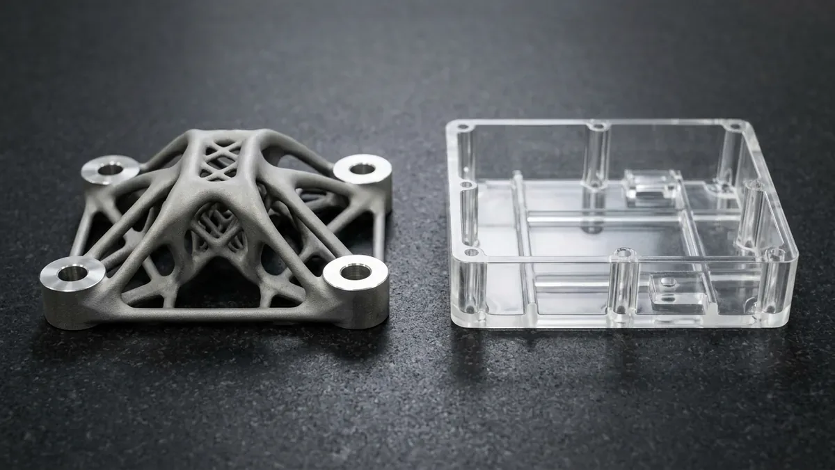
Additive manufacturing spans fundamentally distinct physical processes designed for contrasting engineering objectives. Within modern rapid prototyping and agile production, two optical laser technologies represent the pinnacle of digital fabrication: Selective Laser Melting (SLM) and Stereolithography (SLA).
Choosing between SLM and SLA dictates whether a prototype delivers structural, end-use metallurgic performance or ultra-fine, optical-grade aesthetic fidelity. While SLM utilizes high-energy thermal laser optics to consolidate solid engineering metal alloys, SLA deploys ultraviolet photopolymerization to cross-link liquid resins into smooth, non-porous geometries.
At AS Prototypes, our precision additive facility operates industrial multi-laser powder bed platforms alongside large-format resin vat systems. Through our integrated metal 3D printing services, SLA resin 3D printing, and high-speed CNC machining services, we assist product development teams worldwide in aligning CAD architectures with manufacturing realities. This engineering white paper presents an in-depth comparison of process physics, mechanical benchmarks, surface finishes, secondary machining workflows, and design-for-manufacturing (DFM) rules.
The core distinction between SLM and SLA lies in the thermodynamic state transition of the raw feedstock. SLM relies on complete thermal fusion of spherical metallic particles, achieving metallurgical bonds equivalent to forged or wrought billets. Conversely, SLA relies on photon-initiated covalent cross-linking of thermoset liquid polymers at ambient room temperatures.
Engineering selection hinges primarily on four project constraints: mechanical load bearing capacity, continuous operating temperature, geometric detail resolution, and secondary post-processing cycles. The following decision matrix highlights foundational operational differences:
Executive Summary & Engineering Takeaways (BLUF)
- Core Focus & DFM Scope: Actionable shop-floor engineering guidelines for SLM vs SLA 3D Printing, covering material selection, geometric tolerancing, and defect prevention.
- Dimensional Accuracy Baseline: Industrial SLA/DLP holds ±0.10 mm (±0.004″); SLS/MJF nylon holds ±0.20 mm per 100 mm (±0.002″/in); DMLS metal builds + secondary CNC mating interfaces hold ±0.010 mm (±0.0004″).
- Layer Resolution & Post-Finishing: Build layers from 25–100 µm (0.001″–0.004″) upgraded via media tumbling, vapor smoothing, bead blasting (#120 glass bead), or 3/4/5-axis CNC datum skimming.
- Build Orientation & Metrology: Strategic Z-axis orientation to minimize staircase anisotropy and thermal distortion, verified via 2.5D optical vision metrology (VMS), Go/No-Go pin gauging, and tactile CMM probing on CNC post-machined metal datums.
- Ex-Factory Turnaround: 4 to 8 business days for raw/unfinished additive prototypes; 7 to 12 business days for vapor-smoothed, plated, or hybrid CNC post-machined parts (excluding 3–5 days air transit).
Article Engineering Navigation
- 1. Physical Working Principles & Thermal Mechanics
- 2. Material Properties, Mechanical Performance, & Thermal Ceilings
- 3. Surface Roughness, Geometric Resolution, & Tolerancing
- 4. Support Structures, Post-Processing Pipelines, & Metrology
- 5. Production Economics, Lead Times, & Sourcing Realities
- 6. Design for Additive Manufacturing (DFAM) Checklist
- 7. Technical Engineering FAQ
| Process Metric | SLM (Selective Laser Melting) | SLA (Stereolithography) | Engineering Significance |
|---|---|---|---|
| Feedstock State | Gas-atomized spherical metal powder (15 to 45 μm) | Liquid thermoset photopolymer resin monomers | SLM yields crystalline metal; SLA produces amorphous polymer networks. |
| Laser System & Wavelength | 400W to 1000W continuous Ytterbium fiber laser (1070 nm) | 100mW to 500mW solid-state UV laser (355 nm) | SLM demands intense optical power density to exceed metal melting points. |
| Chamber Atmosphere | Hermetically sealed argon or nitrogen (<100 ppm O2) | Ambient air in climate-controlled build bay (20°C–22°C) | Inert gas prevents high-temperature oxidation in titanium and aluminum. |
| Layer Thickness Window | 30 μm to 60 μm (0.030 to 0.060 mm) | 25 μm to 100 μm (0.025 to 0.100 mm) | SLA allows finer vertical stepping for micro-optical features. |
| As-Built Surface Roughness | Ra 6.3 μm to 10.0 μm (as-printed) | Ra 0.4 μm to 0.8 μm (as-cured) | SLA produces injection-mold-like finishes without abrasive blasting. |
| Linear Dimensional Tolerance | ±0.10 mm to ±0.20 mm (as-sintered) | ±0.05 mm to ±0.15 mm (feature dependent) | Critical bearing fits and sealing faces require CNC post-machining. |
| Part Density & Microstructure | >99.8% relative density (isotropic after heat treat) | 100% solid thermoset (chemically isotropic) | SLM parts withstand pressure-tight hydraulic fluid systems. |
| Production Economics | Custom quoted per CAD DFM (higher capital tooling) | Custom quoted per CAD DFM (economical agile setups) | SLA delivers fast aesthetic iteration; SLM delivers critical mission hardware. |
1. Physical Working Principles & Thermal Mechanics
Understanding process kinetics enables design engineers to avoid structural failures stemming from residual stresses or peeling loads. Both techniques employ galvanometric laser deflection, yet their interaction with the material medium is fundamentally polarized.
Selective Laser Melting (SLM) Powder Bed Dynamics
The SLM production cycle begins by pulling a vacuum on the build chamber and backfilling with high-purity argon (nitrogen only for non-titanium alloys such as 316L and AlSi10Mg) until atmospheric oxygen levels drop below 100 parts per million. Maintaining this inert envelope is mandatory when fusing reactive powders such as Ti-6Al-4V titanium or AlSi10Mg aluminum, preventing catastrophic oxidation or powder embrittlement.
Inside the sealed environment, an automated recoater mechanism equipped with a tungsten carbide or ceramic wiper blade spreads a micro-layer of gas-atomized metal powder across a rigid stainless steel build substrate. A precision fiber laser beam, guided by high-speed scanning galvanometers, selectively traverses the cross-section, elevating localized temperatures beyond 1,650°C to form a dynamic melt pool.
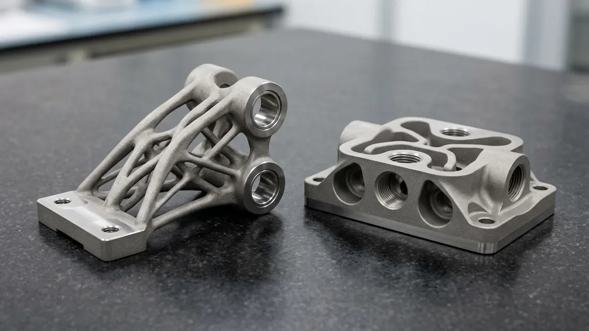
Intense localized heating followed by rapid conduction into the underlying substrate induces severe thermal gradients. Consequently, SLM parts require robust, metallurgically bonded anchor supports. These solid supports serve two critical functions: physically restraining the component against thermal curling forces and conducting excess heat away from the melt pool to prevent recoater blade collisions.
Photochemical Solidification in Stereolithography (SLA)
Stereolithography operates through photopolymerization, a photochemical process in which low-viscosity liquid monomers and oligomers transform into solid, highly cross-linked polymer chains upon exposure to targeted ultraviolet radiation. Operating at ambient room temperature, the process generates negligible thermal shock.
In top-down industrial SLA platforms, an elevator platform lowers incrementally into a deep vat of liquid resin. Following each step-down, a motorized sweeper blade sweeps across the vat surface, establishing a uniform, bubble-free liquid layer. An ultraviolet laser (typically 355 nm wavelength) traces the component slices, initiating radical polymerization at the focal spot.
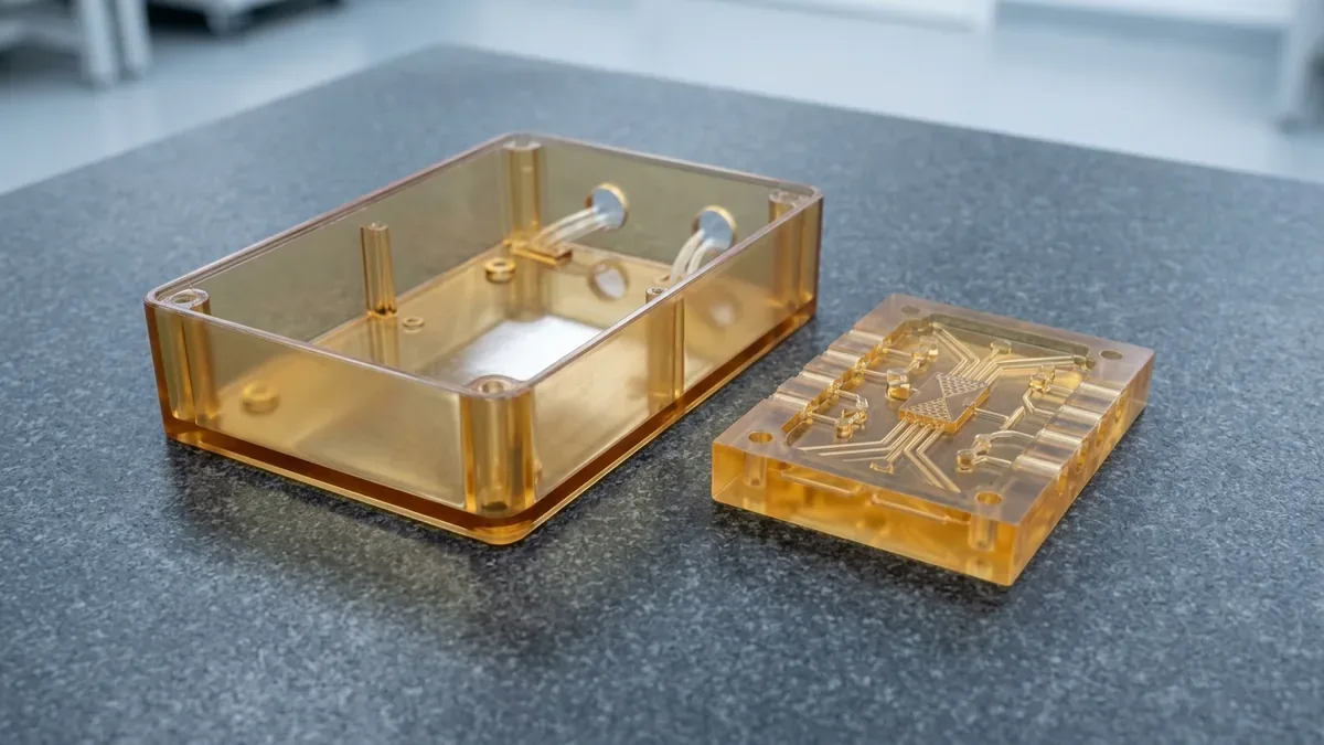
Because thermal expansion stresses are virtually non-existent in SLA, support structures are engineered strictly to anchor overhangs and counter fluid shear forces. Unlike the dense, solid anchors mandatory in metal SLM, SLA supports consist of delicate lattice trusses contacting the part at pinpoint tips (0.30 mm to 0.50 mm diameter), which snip away cleanly during post-processing.
2. Material Properties, Mechanical Performance, & Thermal Ceilings
Material selection dictates the ultimate structural integrity of any manufactured component. While SLM delivers genuine structural metal metallurgy, SLA offers an expansive palette of thermoset formulations tuned to simulate production plastics.
SLM Structural Alloys: True Forged-Equivalent Strength
Metal components produced via SLM achieve full metallurgical consolidation. Because the gas-atomized powder fully liquefies and coalesces, as-printed parts attain relative densities exceeding 99.8%. With appropriate post-build stress relief and hot isostatic pressing (HIP), SLM alloys match or exceed the mechanical properties of conventionally cast or wrought equivalents.
Common industrial SLM alloys include:
- Titanium Ti-6Al-4V (Grade 5): Exceptional strength-to-weight ratio, biocompatibility, and elevated temperature endurance up to 400°C. Primary choice for aerospace structural brackets, turbomachinery components, and orthopedic implants.
- 316L Stainless Steel: Outstanding austenitic corrosion resistance and high ductility (>35% elongation at break). Ideal for marine fluid manifolds, pharmaceutical fittings, and chemical processing valves.
- AlSi10Mg Aluminum: Lightweight cast-equivalent alloy offering high thermal conductivity (130 to 150 W/m·K) and good mechanical stiffness. Widely deployed in automotive heat exchangers, electronics enclosures, and chassis nodes.
- Inconel 718 Superalloy: High-nickel superalloy retaining tensile yield strength of roughly 900 MPa at service temperatures up to 650°C. Used extensively in rocket engine injector heads and gas turbine hot sections.
SLA Photopolymers: Synthetic Resins & Engineering Polymers
SLA photopolymers are categorized as thermosets. Once cured through UV radiation, their cross-linked molecular bonds cannot be remelted without chemical breakdown. While photopolymers do not match the raw tensile strength of structural metals, modern formulations accurately replicate injection-molded thermoplastics for mechanical testing, wind tunnel validation, and functional verification.
Core engineering resin families include:
- Standard & Clear Optical Resins: Yielding glass-like optical clarity, micro-detail resolution, and smooth tactile surfaces. Used for fluid flow visualization, lighting guides, lenses, and aesthetic presentation mockups.
- Tough & Durable Resins (ABS/PP-Like): Formulated to absorb mechanical impact and flexing without brittle fracture (18% to 25% elongation). Suitable for living hinges, snap-fit assemblies, and functional prototype enclosures.
- High-Temperature Resins: Delivering high Heat Deflection Temperatures (HDT up to 250°C under 0.45 MPa load). Crucial for hot air duct testing, mold inserts, and under-the-hood automotive sensor housings.
- Biocompatible & Dental Formulations: Engineered for mucosal contact, surgical drill guides, aligners, and medical wearable prototypes meeting international biological safety standards.
| Mechanical & Thermal Metric | SLM Ti-6Al-4V (Heat Treated) | SLM 316L Stainless | SLA Tough Resin (ABS-Like) | SLA High-Temp Resin |
|---|---|---|---|---|
| Ultimate Tensile Strength (UTS) | 950 to 1,050 MPa | 580 to 680 MPa | 45 to 55 MPa | 50 to 65 MPa |
| Tensile Modulus | 110 to 118 GPa | 190 to 205 GPa | 2.2 to 2.8 GPa | 3.5 to 4.2 GPa |
| Elongation at Break | 12% to 16% | 35% to 45% | 18% to 25% | 2% to 4% |
| Heat Deflection Temp (0.45 MPa) | ~400°C (Service Temp) | ~550°C (Service Temp) | 55°C to 65°C | 230°C to 260°C |
| Long-Term UV & Moisture Resistance | Completely impervious (Immune) | Completely impervious (Immune) | Gradual UV yellowing & embrittlement | Moderate hygroscopic moisture uptake |
3. Surface Roughness, Geometric Resolution, & Tolerancing
Surface finish and dimensional repeatability define the post-processing burden of each additive method. SLA is renowned for producing master patterns that require minimal hand finishing, whereas as-sintered SLM surfaces mirror the granular texture of fine investment castings.
In SLM metal printing, surface roughness is governed by the 15 to 45 μm spherical powder particle size and overlapping laser melt tracks. As-built horizontal surfaces average Ra 6.3 μm, while steep overhangs and downward-facing faces reach Ra 10.0 to 12.5 μm due to partially sintered particles adhering to the molten boundaries.
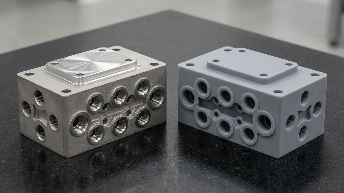
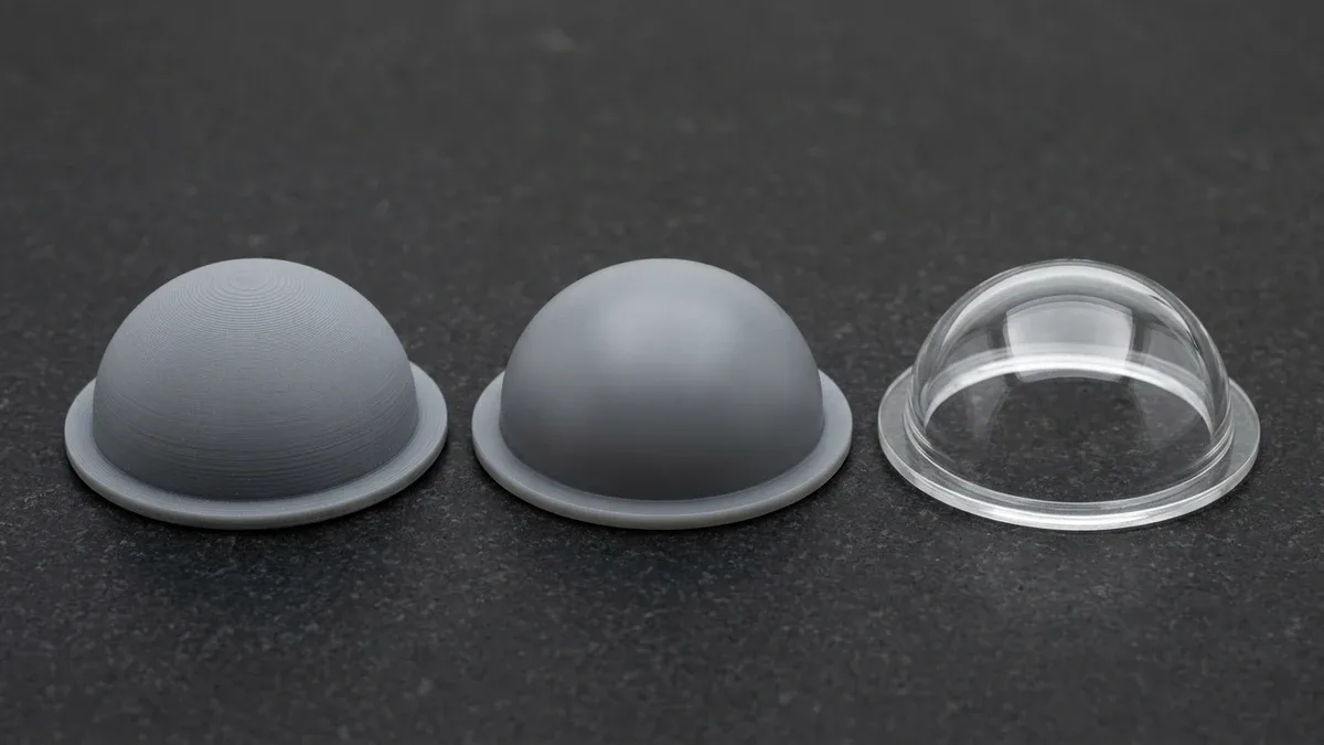
Conversely, SLA produces an ultra-smooth surface finish with an average as-cured roughness of Ra 0.4 μm to 0.8 μm. Because the liquid resin fills micro-crevices and cures uniformly across laser passes, stepped layer lines are nearly invisible at 50 μm layer slicing. With quick light sanding and a clear lacquer coat, SLA optical components achieve specular transparency (Ra <0.1 μm).
Regarding dimensional accuracy, SLA can achieve ±0.05 mm across small feature envelopes (<100 mm). SLM as-sintered geometries achieve ±0.10 mm to ±0.20 mm. For critical mating interfaces, bearing journals, and O-ring sealing grooves, our shop integrates secondary 3-axis and 4-axis CNC milling, bringing critical tolerances into the ±0.010 mm to ±0.020 mm range.
4. Support Structures, Post-Processing Pipelines, & Metrology
A 3D print is only as reliable as its post-processing lifecycle. SLM and SLA demand completely contrasting workflows once the build cycle concludes.
The SLM Post-Processing Ecosystem
When an SLM build finishes, the components remain firmly anchored to a thick steel or aluminum base plate, surrounded by un-sintered metal powder. The post-processing sequence requires strict metallurgical controls:
- Powder Depowdering & Sieving: The chamber is vacuum-cleaned, and loose powder is evacuated into ultrasonic sieving stations for closed-loop inert recycling.
- Stress-Relief Annealing: Before cutting parts off the plate, the entire build plate is transferred to an inert vacuum or argon atmosphere furnace. Subjected to controlled thermal soak cycles (e.g., 650°C to 800°C for titanium alloys), residual tensile stresses are eliminated, preventing severe dimensional distortion upon parting.
- Wire EDM Parting: A precision wire electrical discharge machine (wire EDM) slices cleanly between the base plate and the component bottom supports, detaching the parts with zero mechanical deflection.
- Support Removal & CNC Machining: Sacrificial metal support lattices are machined away or manually ground. Critical alignment pins, threads, and sealing faces are finish-machined on high-speed CNC machining centers.
- Surface Refinement: Parts undergo glass bead blasting (#100 to #150 grit), ceramic tumbling, or chemical passivation (ASTM A967 for stainless alloys) to achieve uniform visual aesthetics.
The SLA Post-Processing Ecosystem
SLA post-processing is fundamentally chemical and optical:
- Solvent Washing: The build platform is transferred to automated agitated solvent wash stations. High-purity Isopropyl Alcohol (IPA) or Tripropylene Glycol Monomethyl Ether (TPM) dissolves unreacted liquid resin from cavities and micro-channels.
- Ultraviolet Post-Curing: Green-state SLA parts contain unpolymerized bonds. Placing the parts inside a calibrated UV curing chamber equipped with controlled heating (60°C) cross-links remaining oligomers, maximizing tensile strength and modulus.
- Support Snapping & Micro-Sanding: Pinpoint support structures are snipped with precision micro-flush cutters. Residual contact pips are lightly hand-sanded using #400 to #1000 grit wet sandpaper.
- Protective & Optical Finishing: Because crosslinked thermoset SLA resins cannot be solvent vapor-smoothed, optical parts undergo progressive wet-sanding (#400 to #2000 grit) followed by a UV-resistant clear acrylic spray coat, or are primed and painted in custom Pantone shades to prevent ambient UV yellowing.
Dimensional verification is conducted in our climate-controlled metrology lab. Using bridge coordinate measuring machines (CMM) equipped with ruby-tipped probes for CNC post-machined SLM/DMLS metal datums alongside non-contact 2.5D optical vision measuring systems (VMS) and Go/No-Go pin gauges for SLA photopolymer housings, we inspect key features against ASME Y14.5 GD&T specifications.
5. Production Economics, Lead Times, & Sourcing Realities
Total program cost involves equipment amortization, feedstock expenses, consumable gas, and labor-intensive post-processing cycles. Balancing these economic factors determines when to utilize each technology:
SLA remains unbeatable for rapid visual proof-of-concept prototypes, ergonomics evaluation, and aesthetic master models for rapid prototyping. Raw resin costs are economical, machine throughput is rapid, and support removal requires minimal labor. A full batch of detailed SLA enclosures can be printed, washed, UV-cured, and inspected within an agile turnaround.
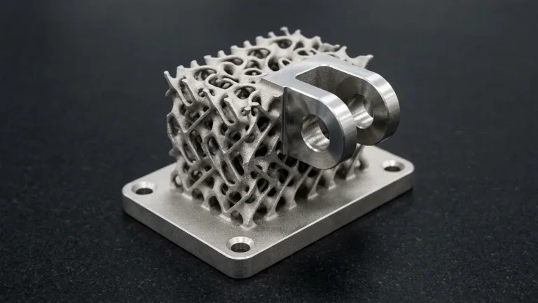
SLM involves higher investment due to high-power fiber laser systems, inert argon consumption, explosion-proof powder handling infrastructure, and mandatory secondary thermal annealing and wire EDM cutting. However, when an engineering application requires lightweight generative titanium brackets, conformal liquid cooling jackets, or high-temperature rocket manifolds that are impossible to machine via subtractive CNC alone, SLM provides unmatched manufacturing freedom.
At AS Prototypes, standard turnaround schedules for rapid additive prototypes are structured as follows:
- CAD DFM Review & Formal Quoting: Completed within 24 hours.
- Rapid Prototyping (SLA Resins & Standard SLM Builds): Released ex-factory in 4 to 8 business days.
- Complex Post-Machined SLM Parts (Wire EDM, CNC Milling, Surface Finishing): Completed ex-factory in 7 to 12 business days.
- International Logistics: Expedited express air courier delivery via DHL, FedEx, or UPS within 3 to 5 business days.
6. Design for Additive Manufacturing (DFAM) Checklist
Designing components specifically for the additive envelope eliminates premature print failures and cuts unnecessary machining costs. Review this quick DFAM checklist during CAD modeling:
| CAD Feature | SLM Metal Guideline | SLA Resin Guideline |
|---|---|---|
| Minimum Wall Thickness | 0.40 mm to 0.60 mm (prevent thermal warping) | 0.40 mm (supported), 0.60 mm (unsupported) |
| Self-Supporting Angle | ≥45° from horizontal (steeper for large overhangs) | ≥30° from horizontal without support anchors |
| Internal Cavities & Trapped Material | Incorporate ≥4.0 mm drain holes for loose powder | Incorporate ≥2.0 mm vent holes to avoid suction cup force |
| Thread Fabrication | Pilot holes printed undersized, then CNC tapped | Use brass threaded heat-set or press-fit ultrasonic inserts |
| Machining Stock Allowance | Add 0.80 mm to 1.50 mm on critical datum faces | Not required (print directly to nominal dimensions) |
7. Technical Engineering FAQ
Standard SLA resins are primarily designed for form, fit, and visual validation because thermoset resins can experience UV degradation and moisture absorption over extended outdoor exposure. However, specialized high-temperature, ceramic-filled, and tough engineering resins withstand moderate mechanical stress, snap-fit assembly, and short-run functional testing.
SLM requires industrial gas-atomized metal alloy powders, continuous inert argon gas circulation, high-power fiber lasers, and explosion-proof filtration systems. Furthermore, mandatory secondary post-processing including stress-relief vacuum furnace heat treatment, wire EDM plate separation, and high-speed CNC precision machining of critical mating faces adds technical labor and cycle time.
Yes. SLM metal components achieve full metallurgical density exceeding 99.8% with uniform crystalline grain structures after stress-relief annealing. They weld, tap, mill, drill, and spark-erode comparably to wrought or forged alloys. Finish-machining O-ring grooves, precision bearing bores, and threads is standard shop practice.
As-built SLM parts feature a micro-weld pool texture with surface roughness ranging from Ra 6.3 to 10.0 micrometers, which can be improved to Ra 3.2 micrometers via bead blasting or Ra 0.8 micrometers via secondary CNC machining. In contrast, SLA parts achieve Ra 0.4 to 0.8 micrometers directly out of the UV curing chamber, producing an ultra-smooth finish equivalent to injection-molded plastics.
Our quality assurance lab operates bridge coordinate measuring machines (CMM) equipped with ruby-tipped probes to verify GD&T tolerances down to ±0.010 mm on CNC post-machined SLM metal interfaces, while non-contact 2.5D optical vision measuring systems (VMS) and mating assembly fit-up checks verify SLA polymer components without clamping distortion.
Accelerate Hardware Validation with Industrial 3D Printing & Hybrid CNC
Bridge additive design freedom with precision CNC datum finishing and polyurethane vacuum casting. Upload your 3D CAD assemblies (STEP/IGES/STL) to evaluate material selection, functional tolerances, and batch unit economics.
Request an Additive & Prototyping DFM Analysis