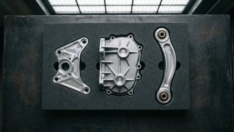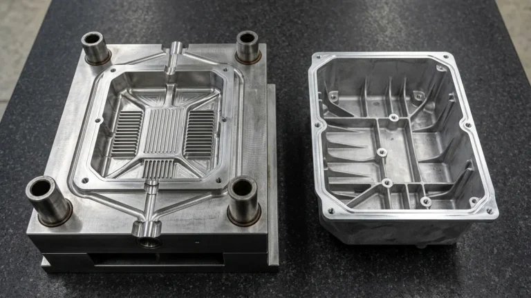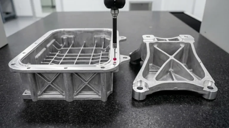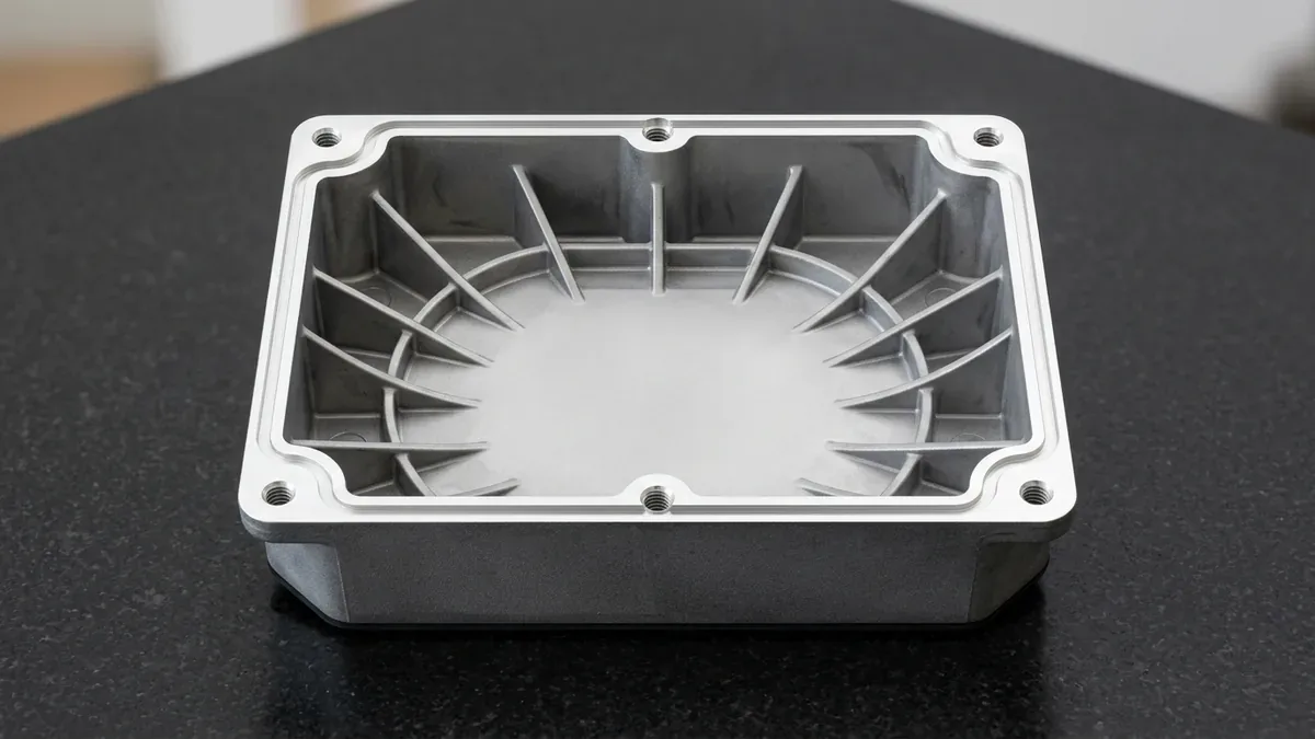
High-pressure die casting (HPDC) transforms molten aluminum, magnesium, and zinc alloys into complex, thin-walled, near-net-shape structural housings within cycle times measured in seconds. However, the extreme phase-change density shift between liquid metal and solid dendrites presents a formidable physics challenge for product designers and toolmakers alike.
When molten alloy enters the hardened tool steel die cavity at temperatures exceeding 650°C and velocities between 30 and 55 m/s, it rapidly begins shedding thermal energy into the mold walls. As metal transitions across its mushy freezing zone, volumetric shrinkage naturally concentrates at the thickest geometric sections. Without directional solidification and continuous hydrostatic feeding, these isolated thermal hot spots starve, forming destructive internal porosity, leak paths in pressure vessels, and surface depressions that ruin Class-A cosmetic finishes.
At AS Prototypes, our foundry and tooling engineering divisions combine high-tonnage cold-chamber and hot-chamber die casting machines with multi-axis CNC secondary machining centers. In this comprehensive engineering guide, we dissect the thermodynamic mechanisms of casting shrinkage, derive Chvorinov’s solidification modulus, evaluate alloy-specific contraction rates, analyze hydraulic squeeze pin mechanics, and present proven design for manufacturability (DFM) guidelines to achieve completely dense, leak-proof metal components.
- 1. The Three Thermodynamic Stages of Metal Casting Contraction
- 2. Chvorinov’s Rule and Geometric Modulus Mechanics
- 3. Casting Alloy Solidification and Shrinkage Characteristics
- 4. Shot Intensification Kinematics and Hydraulic Squeeze Pins
- 5. Porosity Forensics: Shrinkage Porosity vs Gas Entrapment
- 6. Die Thermal Balance and Oil Thermoregulation
- 7. Secondary CNC Machining and the Chilled Skin Rule
- 8. Comprehensive Design for Manufacturability (DFM) Rules
- 9. Technical Engineering FAQ
1. The Three Thermodynamic Stages of Metal Casting Contraction
To control volumetric and linear contraction effectively, engineers must isolate the three consecutive physical phases that occur as thermal energy leaves the casting system.
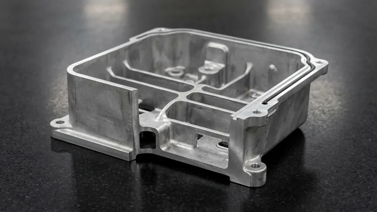
1.1 Liquid Thermal Contraction
Liquid thermal contraction takes place while the molten alloy cools from its pouring temperature (Tpour, typically 660°C to 700°C for aluminum A380) down to the alloy liquidus boundary (Tliquidus, approx. 595°C). During this stage, the volumetric loss is governed by the volumetric thermal expansion coefficient of the liquid state (βliquid):
Liquid contraction typically accounts for 1.5% to 2.0% volume reduction. Because the alloy remains entirely fluid during this phase, hydraulic pressure from the injection shot cylinder effortlessly displaces fresh molten alloy from the cold chamber sleeve into the cavity, compensating for early volumetric loss without inducing casting defects.
1.2 Solidification Phase-Change Shrinkage (The Critical Defect Phase)
Solidification shrinkage occurs within the “mushy zone” between the liquidus temperature (Tliquidus) and solidus temperature (Tsolidus, approx. 540°C for A380). As primary aluminum dendrites nucleate and grow, latent heat of fusion is released, accompanied by a abrupt density discontinuity between the disordered liquid metal and the dense crystalline solid lattice:
For hypoeutectic and eutectic aluminum alloys such as A380, A383, and ADC12, liquid density at liquidus is approximately 2.45 g/cm3, whereas room-temperature solid density reaches 2.74 g/cm3. This phase change generates a severe 5.5% to 6.5% volumetric contraction.
If the gating system or thin connecting walls solidify before heavy interior sections freeze, feed paths become choked. The isolated molten puddle continues to freeze inward toward its thermal center. Because no external liquid can enter, the physical volume deficit tears open inter-dendritic voids, forming macro-shrinkage cavities or pulling exterior chilled skin inward to produce visible surface sink marks.
1.3 Solid Thermal Contraction (Linear Shrinkage)
Once the casting completely freezes below its solidus point, solid thermal contraction occurs as the part cools from solidus down to ambient workshop room temperature (20°C). Solid contraction is governed by the linear thermal expansion coefficient (αsolid):
For standard aluminum casting alloys, linear shrinkage ranges between 0.5% and 0.7% (approximately 0.005 to 0.007 mm/mm). Mold designers scale up tool steel cavity CAD models by this precise shrink factor (e.g., multiplying nominal part geometry by 1.006) to ensure finished components match print dimensions. During this solid contraction phase, the casting shrinks away from external cavity steel but contracts tightly onto internal steel core pins, necessitating adequate draft angles to prevent galling during part ejection.
2. Chvorinov’s Rule and Geometric Modulus Mechanics
Solidification kinetics in metal casting are fundamentally governed by Chvorinov’s Rule, which relates freezing time directly to part volume and cooling surface area:
Where tsolidification is the total freezing time (seconds), B is the mold thermal mold constant (governed by steel thermal conductivity, alloy latent heat, and contact resistance), V is casting volume (mm3), A is cooling surface area in contact with die steel (mm2), and M = V / A is the geometric thermal modulus (mm).
To achieve sound, porosity-free castings, the solidification sequence must establish a strict directional gradient towards the feeding sources:
Whenever a heavy mounting boss or thick rib junction produces a local modulus Mlocal higher than the adjoining runner or gate modulus Mgate, directional feeding breaks down. The gate freezes prematurely, isolating the hot junction and guaranteeing internal shrinkage porosity.
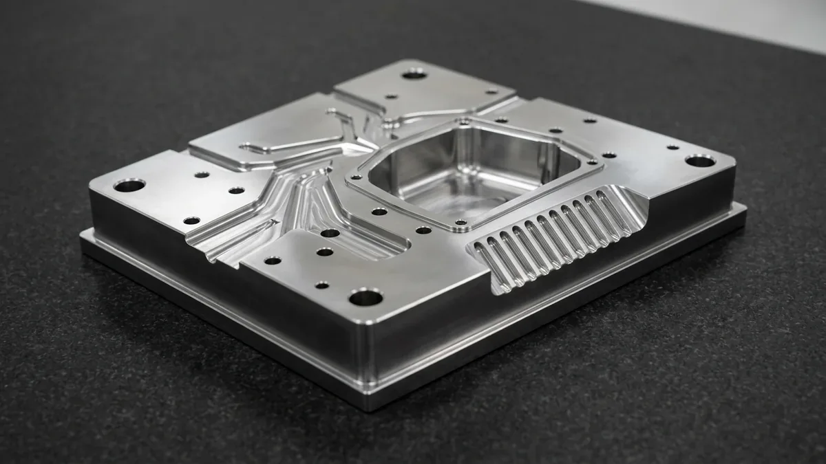
3. Casting Alloy Solidification and Shrinkage Characteristics
Different non-ferrous foundry alloys exhibit distinct solidification temperature ranges, eutectic volume fractions, and contraction behaviors. Alloys with a narrow freezing range (eutectic or near-eutectic) solidify rapidly from the mold surface inward with skin-forming characteristics, while wide-freezing-range alloys undergo extended mushy-zone dendritic growth that elevates shrinkage porosity risks.
| Foundry Alloy | Solidification Range | Volumetric Shrinkage | Linear Shrinkage Rate | Latent Heat of Fusion | Intensification Squeeze |
|---|---|---|---|---|---|
| Aluminum A380 (AlSi8Cu3Fe) | 540°C to 595°C (55°C range) | 5.5% to 6.5% | 0.6% to 0.7% (0.006 mm/mm) | 389 kJ/kg | 70 to 110 MPa |
| Aluminum ADC12 (AlSi11Cu2) | 515°C to 580°C (65°C range) | 5.0% to 6.0% | 0.5% to 0.6% | 410 kJ/kg | 65 to 100 MPa |
| Aluminum A360 (High Corrosion) | 555°C to 595°C (40°C range) | 6.0% to 7.0% | 0.6% to 0.7% | 405 kJ/kg | 80 to 120 MPa |
| Zinc Zamak 3 (ZL0400) | 381°C to 387°C (6°C narrow) | 3.0% to 3.5% | 0.7% (approx. 0.007 mm/mm) | 113 kJ/kg | 25 to 45 MPa |
| Zinc Zamak 5 (ZL0410) | 380°C to 386°C (6°C narrow) | 3.0% to 3.8% | 0.7% | 115 kJ/kg | 30 to 50 MPa |
| Magnesium AZ91D | 470°C to 595°C (125°C wide) | 4.0% to 5.0% | 0.75% to 0.85% | 373 kJ/kg | 60 to 90 MPa |
| Magnesium AM60B (Structural) | 540°C to 615°C (75°C range) | 4.2% to 5.2% | 0.7% to 0.8% | 380 kJ/kg | 65 to 95 MPa |
As demonstrated in the comparison table, Zinc Zamak alloys possess an extremely narrow freezing range (only 6°C) and low pouring temperature. As a result, Zamak alloys solidify with a sharp, well-defined freezing front, making them virtually immune to inter-dendritic shrinkage porosity. Conversely, Magnesium AZ91D features a massive 125°C freezing window, requiring aggressive shot intensification and precision die thermal conditioning to prevent micro-shrinkage networks.
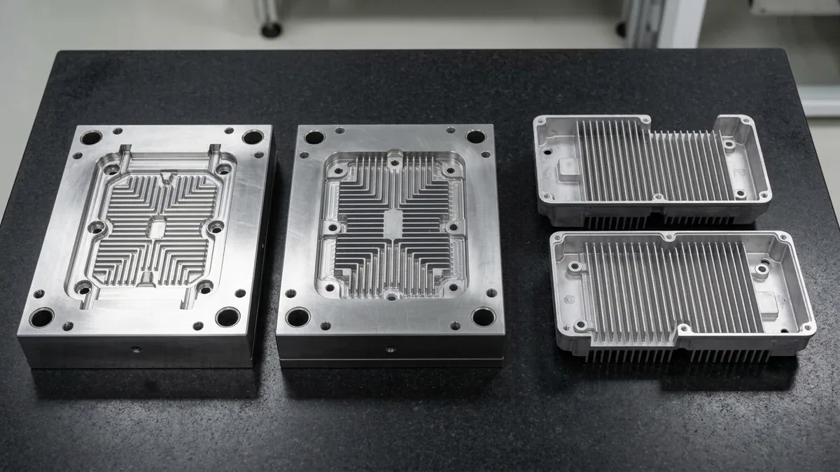
4. Shot Intensification Kinematics and Hydraulic Squeeze Pins
In modern real-time closed-loop die casting machines, the injection cycle is executed in three coordinated mechanical phases:
- Phase 1 (Slow Shot Acceleration): Plunger speed is maintained at 0.2 to 0.4 m/s. This allows the wave front in the shot sleeve to roll forward smoothly without tumbling, preventing early air entrapment in the molten shot.
- Phase 2 (Fast Cavity Injection): Plunger velocity spikes to 2.0 to 6.0 m/s, forcing molten alloy through the narrow in-gates at 30 to 55 m/s to fill the entire cavity in 15 to 40 milliseconds before skin freezing can occur.
- Phase 3 (High-Pressure Intensification): At the instant of cavity fill (impact pressure spike), hydraulic pressure rapidly surges to 80 to 140 MPa within a rise time (Δt) of under 20 milliseconds. This intensification force packs liquid alloy through the still-molten gate into the freezing core, feeding the 5% volumetric solidification shrinkage.
4.1 Mechanical Squeeze Pin Architecture
While Phase 3 intensification feeds shrinkage across standard wall sections, heavy isolated bosses or thick mounting flanges located far from the in-gate cannot be fed once the runner or thin connecting walls freeze. For these critical structural zones, our tooling engineers deploy auxiliary hydraulic squeeze pins directly within the mold cores.
The squeeze pin is a hardened H13 core pin (48 to 52 HRC) actuated by a secondary high-pressure hydraulic cylinder. The mechanical force delivered by the squeeze pin into the mushy metal core is calculated by:
Where Psqueeze is hydraulic line intensification pressure (typically 120 to 200 MPa) and dpin is squeeze pin diameter (typically 6 mm to 20 mm). Actuation timing is critical: the pin must advance after the outer cosmetic skin has formed (avoiding blow-out flash) but before the core has fully crystallized (liquid fraction fL between 0.30 and 0.50). The pin forcefully displaces metal into the consolidating center, completely crushing internal shrink voids and yielding 100% sound, pressure-tight mounting bosses.
5. Porosity Forensics: Shrinkage Porosity vs Gas Entrapment
Accurate metallurgical failure analysis is the first step when troubleshooting die cast porosity. Non-destructive ultrasonic flaw detection and metallurgical micro-sectioning reveal fundamental physical distinctions between gas porosity and shrinkage porosity:
| Forensic Characteristic | Solidification Shrinkage Porosity | Trapped Gas / Air Porosity |
|---|---|---|
| Pore Morphology | Irregular, jagged, dendritic, sponge-like crevices | Smooth, spherical, or oblong rounded bubbles |
| Typical Location | Thermal center of thick bosses, rib roots, corners | Last-to-fill flow convergence points, knit lines |
| Internal Wall Finish | Rough, frosted dendrite branch formations | Polished, shiny internal surface oxide film |
| Root Mechanism | Volumetric contraction without molten metal feed | Turbulent air entrapment or vaporized die lube |
| Primary Solution | Wall coring, squeeze pins, thermal oil balance | High-vacuum evacuation, chill vents, slow shot |
When high-integrity structural applications demand zero internal voids and pressure-tight hermetic seals, our foundry employs High-Vacuum HPDC. By pulling the mold cavity and shot sleeve down to an absolute pressure below 50 mbar prior to metal injection, air entrapment is virtually eliminated. This enables successful post-casting T6 solution heat treatment (500°C soak and water quench) without surface blistering, unlocking exceptional ductility and tensile yield strength in cast structural components.
6. Die Thermal Balance and Oil Thermoregulation
Die casting molds function as high-performance transient heat exchangers. Each cycle, molten alloy deposits thousands of kilojoules of heat into the H13 steel blocks. Maintaining steady-state thermal equilibrium (Qin = Qout) is essential to preserve dimensional stability and prevent localized hot spots that breed shrinkage defects:
If mold steel operating temperature drops below 180°C, molten metal chills prematurely upon contacting cavity walls, causing cold shuts and surface laminations. Conversely, if localized steel regions exceed 280°C, thermal extraction stalls, prolonging solidification times and creating localized shrinkage sink holes.
To establish perfect thermal equilibrium, our tooling utilizes dual-circuit pressurized hot oil thermoregulators (operating at 200°C to 240°C) linked to internal gun-drilled cooling circuits, spiral bubblers in core pins, and copper-beryllium (CuBe) high-conductivity chill inserts in tight pocket corners.
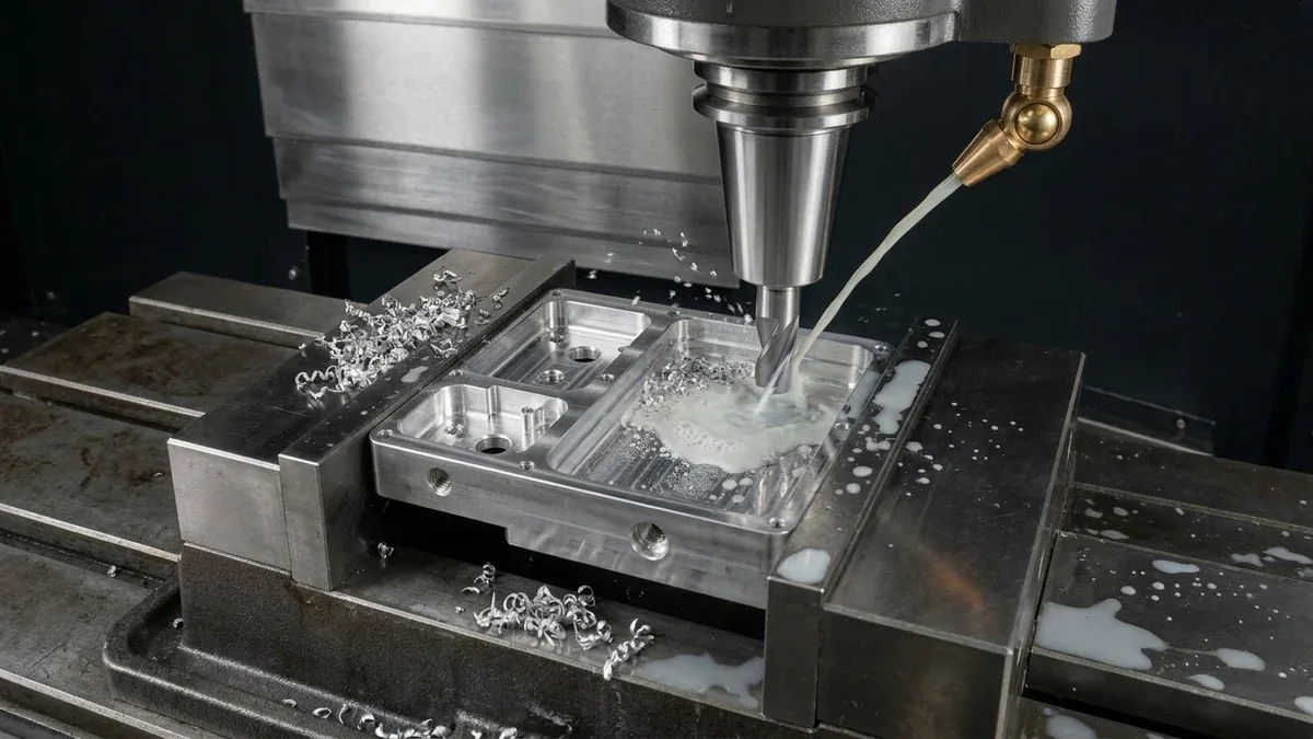
7. Secondary CNC Machining and the Chilled Skin Rule
While precision die casting readily achieves general linear tolerances of ISO 2768-mK, critical interface features—including bearing bores, O-ring seal glands, dowel pin locating holes, and hydraulic manifold faces—demand tighter tolerances down to ±0.010 mm.
When engineering secondary CNC machining services for die cast components, manufacturing engineers must adhere to the Chilled Skin Principle:
- During rapid die cavity fill, the metal contacting the chilled H13 tool steel walls freezes in milliseconds, creating a fine-grained, ultra-dense, completely pore-free “chill skin” measuring 1.0 mm to 1.5 mm deep.
- The interior core of the casting, cooling more slowly, naturally exhibits coarser dendrite grain structures and potential micro-shrinkage pores.
- CNC Machining Depth Rule: Limit secondary machining stock removal to 0.5 mm to 0.8 mm (maximum 1.0 mm) per surface. Removing more than 1.5 mm of material cuts entirely through the dense protective chill layer, exposing the softer interior core and risking pressure seal leaks.
8. Comprehensive Design for Manufacturability (DFM) Rules
Applying the following engineering guidelines during early 3D CAD modeling prevents shrinkage defects, minimizes tooling rework, and guarantees cost-effective production.
Rule 1: Maintain Uniform Nominal Wall Thickness
Uniform walls ensure simultaneous cooling and prevent isolated liquid pools. Target nominal wall thicknesses between 2.0 mm and 3.5 mm for aluminum, 1.2 mm and 2.5 mm for magnesium, and 1.0 mm and 2.0 mm for zinc. Where wall thickness transitions are unavoidable, taper the junction with a gentle transition slope of ≤ 1:3.
Rule 2: Restrict Rib-to-Wall Thickness Ratios to ≤ 0.60
Intersecting ribs add structural rigidity but create thermal mass concentrations at the rib root junction. To prevent visible surface sink marks on the opposite decorative face, design rib base thickness at 40% to 60% of adjoining nominal wall thickness, and incorporate a minimum 1.5 mm fillet radius at the root.
Rule 3: Generously Core Out Solid Mounting Bosses
Solid cylindrical mounting bosses are notorious shrinkage hot spots. Never specify solid bosses. Instead, core out the center of the boss down to the bottom plate, maintaining consistent annular wall thickness. If the boss requires internal threads, cast the cored pilot hole directly to tap drill diameter, or design a stepped recess to facilitate secondary CNC thread milling.
Rule 4: Apply Proper Internal and External Draft Angles
As cast alloys cool, solid thermal contraction causes the metal to shrink away from outer cavity cavities but clamp tightly onto interior steel cores. Specify a minimum of 1.0° to 1.5° draft on external cavity walls, and 2.0° to 3.0° draft on internal core pins and deep pockets to prevent frictional drag, surface scuffing, and hot tearing during mechanical ejection.
Rule 5: Integrate Generous Fillet Radii (R ≥ 1.5 mm)
Sharp 90-degree internal corners concentrate cooling stress and restrict liquid metal feeding. Sharp corners cool from two perpendicular faces, creating localized stress risers that induce hot tears and solidification cracking. Specify internal blend radii of R 1.5 mm to 2.5 mm across all structural intersections.
9. Technical Engineering FAQ
Solidification shrinkage is caused by the physical density increase that occurs when molten alloy transforms into crystalline solid dendrites, generating a 5.0% to 6.5% volumetric contraction in aluminum alloys that creates voids if not fed under high pressure.
Gas porosity forms smooth, spherical, polished voids caused by entrapped air or vaporized die lubricant. In contrast, shrinkage porosity forms irregular, jagged, dendritic crevices located in the thermal center of heavy un-cored sections.
Hydraulic squeeze pins forcefully penetrate the semi-solid mushy core under 120 to 200 MPa localized pressure immediately after cavity fill, mechanically displacing metal into shrinking areas and crushing internal voids.
Die castings feature a dense, pore-free chilled surface layer approximately 1.0 to 1.5 mm deep. Limiting machining removal to 0.5 to 0.8 mm preserves this impervious barrier and prevents cutting into the softer, micro-porous interior core.
Engineering DFM evaluations and detailed tooling quotes are delivered within 24 hours. Rapid prototype bridge tooling and production H13 multi-cavity dies achieve an ex-factory turnaround of 18 to 35 business days for tooling and T1 sample castings (excluding 3 to 5 days international air freight).
Eliminate Die Casting Shrinkage & Porosity with Our Foundry Engineering Team
Optimize H13 die thermal balance, gating geometry, hydraulic squeeze pins, and secondary CNC machining allowances with our in-house high-pressure die casting and tooling engineers. Upload your 3D CAD models (STEP/IGES) and 2D GD&T drawings for a comprehensive solidification and DFM manufacturability assessment.
Upload 3D CAD for Die Casting & Tooling DFM Review