Manufacturing Materials: Metals, Plastics, Composites & Spec Charts
Selecting the right manufacturing materials governs part strength, thermal stability, and cycle time across Computer Numerical Control (CNC) machining, sheet metal, molding, and additive processes. Our in-house machine shop stocks over 100 traceable alloys, polymers, composites, and ceramics, delivering prototypes in 4–8 business days ex-factory to ±0.010 mm (±0.0004″).
Metals & Alloys for CNC Machining, Sheet Metal & Tooling
Engineering metals and alloys provide isotropic crystal strength, high thermal conductivity, and predictable elastic moduli across precision CNC machining services, sheet metal forming, and mold tooling. While 6061-T6 aluminum serves as the baseline machinability reference, high-load brackets, surgical shafts, and die-casting cavities demand specialized alloy tempers and heat-treatment schedules.
Choosing between wrought bar, stretched plate, and cast tooling stock directly dictates part flatness after heavy pocket roughing. Compare the mechanical properties, cutting windows, cost ratios, and application boundaries of our stocked metal grades below:
| Alloy Family & Grade | Density (g/cm³) & Yield / UTS (MPa / ksi) | Hardness & Cutting Speed Vc (m/min) | Relative Part Cost Ratio & Tolerance (mm) | Recommended Application / When to Choose |
|---|---|---|---|---|
| Aluminum 6061-T6 / 6061-T651 | 2.70 g/cm³ | Yield: 276 MPa (40.0 ksi) | UTS: 310 MPa (45.0 ksi) | 95 HB | Vc ≈ 300–500 m/min, fz ≈ 0.08–0.18 mm/tooth | 1.0x (Baseline) | ±0.010 mm (±0.0004″) critical / ISO 2768-mK | Default structural enclosures, fixture plates, and anodized housings; specify T651 stretched plate to prevent bow on deep pockets. |
| Aluminum 7075-T651 | 2.81 g/cm³ | Yield: 503 MPa (73.0 ksi) | UTS: 572 MPa (83.0 ksi) | 150 HB | Vc ≈ 250–400 m/min, fz ≈ 0.08–0.15 mm/tooth | 1.3x–1.6x | ±0.010 mm (±0.0004″) | High-stress aerospace ribs, robotic linkages, and drone arms; never fusion-weld (hot cracking risk) or anneal above 110 °C. |
| Aluminum 5052-H32 & 6063-T5 | 2.68–2.70 g/cm³ | Yield: 145–193 MPa (21.0–28.0 ksi) | 60–68 HB | Vc ≈ 250–450 m/min | Thermal: 138–200 W/m·K | 0.9x–1.1x | Sheet bend ±0.20–±0.40 mm / CNC ISO 2768-mK | 5052-H32 for tight 1.0T–1.5T sheet metal bending and marine panels; 6063-T5 for high-conductivity finned heat sinks. |
| Aluminum 2024-T3 & MIC-6 Cast Plate | 2.78–2.80 g/cm³ | Yield: 345 MPa (2024) / 110 MPa (MIC-6) | 120 HB (2024) / 65 HB (MIC-6) | Vc ≈ 220–380 m/min | 1.3x–1.5x | Flatness ≤ 0.02 mm per 100 mm on MIC-6 | 2024-T3 for cyclic-fatigue aircraft tension members; MIC-6 cast plate for distortion-free metrology baseplates (use Helicoils for threads). |
| Stainless Steel 303, 304 & 316L | 7.93–8.00 g/cm³ | Yield: 205–240 MPa (29.7–34.8 ksi) | UTS: 515–620 MPa | 75–92 HRB | Vc ≈ 120–160 m/min (303) / 70–110 m/min (304/316L) | 1.6x–2.4x | ±0.010 mm (±0.0004″) | 303 for high-speed turned shafts (do not weld); 304 for food/medical brackets; 316L (2%–3% Mo) for welded subsea and semiconductor hardware. |
| Stainless Steel 17-4PH, 440C & 416 | 7.75–7.80 g/cm³ | Yield: 1,000–1,170 MPa (17-4PH H900) / 1,900 MPa UTS (440C) | 40–44 HRC (17-4PH) | 58–60 HRC (440C) | 38–42 HRC (416) | 2.2x–3.2x | ±0.005 mm (±0.0002″) ground / wire EDM | 17-4PH for high-torque surgical and aerospace actuators; 440C for hardened bearing races and valve spools; 416 for free-machining valve stems. |
| Carbon & Alloy Steels (1018, 1045, 4140, 4340) | 7.85 g/cm³ | Yield: 310–370 MPa (1018/1045) | 655–1,100 MPa (4140/4340) | 15–22 HRC (1045) | 28–32 HRC pre-hard / 45–52 HRC Q&T (4140/4340) | 1.2x–2.0x | ±0.010 mm (±0.0004″) | 1018/1045 for black-oxide fixture blocks; 4140 and 4340 chromoly for heavy-duty splined shafts, drive gears, and high-fatigue couplings. |
| Tool & Mold Steels (D2, A2, P20, NAK80, S136, H13) | 7.70–7.86 g/cm³ | Yield: 850–1,650 MPa (dependent on quench & temper state) | P20: 28–34 HRC | NAK80: 37–42 HRC | S136: 48–52 HRC | H13: 44–50 HRC | D2/A2: 58–62 HRC | 2.0x–3.8x | ±0.005 mm (±0.0002″) via Sodick wire EDM & grinding | D2/A2 for stamping dies; P20/NAK80 for pre-hardened injection molds; quenched S136 for mirror/LSR cavities; H13 for aluminum/zinc die-casting dies. |
| Titanium Alloys (Ti-6Al-4V Grade 5 & Grade 2) | 4.43–4.51 g/cm³ | Yield: 880 MPa (128 ksi, Gr. 5) / 275 MPa (40.0 ksi, Gr. 2) | 34–36 HRC (Gr. 5) | Vc ≈ 45–65 m/min with high-pressure coolant | 3.5x–6.0x | ±0.010 mm (±0.0004″) | Grade 5 for aerospace blisks, orthopedic housings, and subsea pressure hulls; Grade 2 for corrosion-proof chemical heat exchangers. |
| Copper, Brass & Bronze (C3604, C11000, C10100, C93200, C17200) | 8.25–8.94 g/cm³ | Yield: 200–310 MPa (Brass/Cu) | 1,100 MPa (C17200 BeCu) | C3604: 100% machinability | C10100 OFHC: 391 W/m·K | C17200: 38–42 HRC | 1.4x–3.5x | ±0.010 mm (±0.0004″) | C3604/C36000 for Swiss-turned RF fittings; C11000/C10100 for busbars and vacuum cold plates; C93200 for bushings; C17200 for high-strength contacts. |
| Magnesium (AZ31B / AZ91D) & Die-Cast Alloys (Zamak 3/5, ADC12, A380) | 1.77–1.81 g/cm³ (Mg) | 2.71 g/cm³ (ADC12/A380) | 6.60–6.70 g/cm³ (Zamak 3/5) | 60–70 HB (Mg) | 80–95 HB (ADC12/Zamak) | Vc ≈ 300–600 m/min | 1.5x–2.5x (CNC Mg) | Volume-driven for HPDC tooling | AZ31B/AZ91D for ultralight UAV gimbals; Zamak 3/5 for 0.8 mm thin-wall housings; ADC12/A380 for EV housings (limit post-CNC skim to 0.3–0.6 mm). |
Aluminum Alloy Strategy
6061 · 7075 · 5052For deep-pocketed housings, we specify 6061-T651 stress-relieved plate and run an intermediate 150–165 °C annealing cycle. When comparing 6061-T6 vs. 7075-T651 aluminum, remember that 6061-T6 cold sheet bending requires a 3.0T–6.0T internal radius to avoid grain-boundary cracking, whereas 5052-H32 bends cleanly at 1.0T–1.5T. Explore our full aluminum alloys CNC machining guide.
Stainless, Carbon & Tool Steels
316L · 17-4PH · S136Austenitic 304 and 316 vs. 316L stainless steel form a work hardening layer if tools rub, so our CNC steel machining workflows hold chip loads above 0.05 mm/tooth. For 17-4PH stainless steel and hardened D2/S136 inserts, Sodick wire Electrical Discharge Machining (EDM) uses 1 rough cut plus 3–4 skim cuts to hold recast layers ≤ 1–2 µm.
Titanium, Copper & Die-Cast Metals
Ti64 · C101 · ADC12Because Ti-6Al-4V conducts heat poorly (6.7 W/m·K), our titanium CNC machining strategy pairs climb milling with high-pressure coolant to prevent notch wear. Review our brass vs. bronze vs. copper guide and brass CNC machining rules for conductive parts, or our high-pressure die casting (HPDC) and Zamak zinc die casting guides (limit post-CNC skimming to 0.3–0.6 mm).
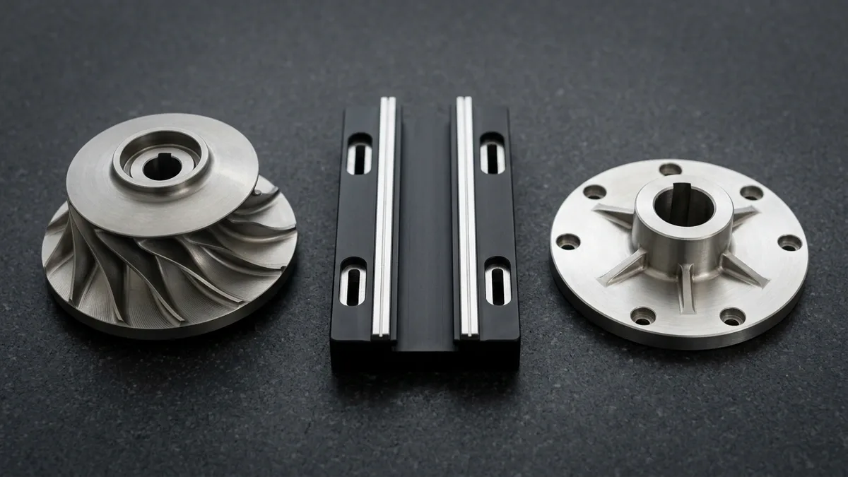
Each alloy exhibits distinct surface reflectance and functional micro-textures after multi-axis milling and turning (as shown in the CNC-machined metal alloy comparison below). Inspecting the 5-axis simultaneous milled Ti-6Al-4V shrouded impeller blades, the masked bare-aluminum datum rails on the hard-anodized 6061-T6 linear stage base, and the brushed 17-4PH stainless ribbed coupling flange illustrates how cutter geometry adapts to substrate hardness:
Matching Metal Stock Form & Grain Direction to Part Geometry
Prismatic valve bodies, optical mounts, and heat-sink plates are routed to our Brother, Fanuc, and Mazak 3-axis and 4-axis Vertical Machining Centers (VMCs), which represent 75%–85% of shop capacity. Simultaneous 5-axis CNC machining on our AFMING trunnion center is reserved strictly for impellers, compound-angle manifolds, and contoured Ti-6Al-4V airframes.
Concentric shafts, threaded sensor bodies, and micro-medical pins run on Takisawa CNC turning centers and Star Swiss-type sliding-headstock lathes to hold ±0.005 mm (±0.0002″) diameter concentricity. For weight-critical structures, compare specific stiffness values in our lightweight metals engineering guide.
Engineering & High-Performance Thermoplastics
Engineering thermoplastics deliver electrical insulation, chemical inertness, low-friction wear resistance, and up to 50%–80% weight reduction over aluminum across CNC machining and custom plastic injection molding. However, polymers exhibit 30×–170× lower elastic moduli and 3×–8× higher thermal expansion than steel, requiring strict control of cutting heat, clamping pressure, and hygroscopic moisture conditioning.
Use the quantitative polymer matrix below to compare Heat Deflection Temperature (HDT), mold shrinkage, machining speeds, and dimensional stability across our stocked plastics:
| Polymer Grade | Density (g/cm³) & Tensile Strength (MPa / ksi) | Flexural Modulus (GPa) & HDT @ 1.8 MPa (°C) | Mold Shrinkage (%) & CNC Speed Vc (m/min) | Achievable CNC Tolerance (mm / in) | Recommended Application / When to Choose |
|---|---|---|---|---|---|
| PEEK Natural (450G) & PEEK-GF30 / CF30 | 1.30–1.51 g/cm³ | 98 MPa (14.2 ksi) natural | 175–210 MPa reinforced | 4.0 GPa (Natural) | 10.5–22.0 GPa (GF30/CF30) | HDT: 152–315 °C | 1.1%–1.5% (Natural) / 0.2%–0.5% (GF/CF) | Vc ≈ 150–250 m/min | ±0.015 mm (±0.0006″) critical / ISO 2768-mK | Semiconductor wafer rings, high-vacuum valve seats, and autoclave medical trials (ISO 10993 / USP Class VI raw resin); anneal at 200 °C between rough and finish cuts. |
| Ultem 1000 (PEI) & Ultem 2300 (30% GF) | 1.27–1.51 g/cm³ | 110 MPa (16.0 ksi) Ultem 1000 | 165 MPa (23.9 ksi) Ultem 2300 | 3.3 GPa (1000) | 9.0 GPa (2300) | HDT: 200–210 °C | 0.5%–0.7% (1000) / 0.2%–0.4% (2300) | Vc ≈ 140–220 m/min | ±0.015 mm (±0.0006″) / ISO 2768-mK | Aerospace cabin brackets, high-voltage 5G RF insulators, and UL94 V-0 flame-retardant sterilization trays. |
| POM-C (Acetal Copolymer) & Delrin (POM-H) | 1.41–1.42 g/cm³ | 62–72 MPa (9.0–10.4 ksi) | 2.6–3.1 GPa | HDT: 110–125 °C | Moisture < 0.25% | 1.8%–2.2% | Vc ≈ 200–350 m/min | ±0.015 mm (±0.0006″) / ISO 2768-mK | Top choice for precision CNC spur gears, lead-screw nuts, and low-friction bushings; avoid when parts require adhesive bonding or painting. |
| PTFE (Teflon) Virgin & 25% Glass-Filled | 2.15–2.25 g/cm³ | 20–30 MPa (2.9–4.4 ksi) | 0.5–1.4 GPa | HDT: 55 °C (Service to 260 °C) | Compression sintered | Vc ≈ 150–300 m/min | ±0.050 mm (±0.0020″) / ISO 2768-c | Ultra-low friction (µ ≈ 0.05) chemical seals, cryogenic gaskets, and RF standoffs; avoid for high mechanical loads due to cold-flow creep. |
| PC (Polycarbonate) Optical & Mechanical | 1.20 g/cm³ | 65 MPa (9.4 ksi) | Izod Impact > 600 J/m | 2.3 GPa | HDT: 130 °C | 88%–90% Light Transmittance | 0.5%–0.7% | Vc ≈ 180–300 m/min | ±0.020 mm (±0.0008″) / ISO 2768-mK | Shatter-proof machine guards, medical fluid housings, and clear light pipes; pre-anneal at 110–120 °C before DCM vapor polishing. |
| PMMA (Optical Acrylic) | 1.18–1.19 g/cm³ | 70 MPa (10.2 ksi) | 3.0 GPa | HDT: 95 °C | 92% Optical Transmittance | 0.4%–0.7% | Vc ≈ 150–280 m/min | ±0.020 mm (±0.0008″) / Ra 0.02 µm SPDT | Automotive headlamp lenses, light guides, and bonded microfluidic chips; anneal at 70–80 °C and finish via diamond buffing (SPI A-1) or SPDT. |
| Nylon PA6, PA66 & PA66-GF30 | 1.14–1.36 g/cm³ | 75–85 MPa (unfilled) | 170–185 MPa (GF30) | 2.8 GPa (unfilled) | 8.5 GPa (GF30) | HDT: 75–250 °C | 1.2%–1.8% (unfilled) / 0.3%–0.8% (GF30) | Vc ≈ 180–300 m/min | ±0.025 mm (±0.0010″) / ISO 2768-mK | Wear sheaves, cable rollers, and under-hood intake brackets; avoid unfilled PA6/PA66 in wet environments (1.5%–2.8% moisture swell). |
| ABS, HDPE / UHMW-PE & PP | 0.90–1.05 g/cm³ | 25–42 MPa (3.6–6.1 ksi) | 1.1–2.3 GPa | HDT: 65–98 °C | 0.4%–0.7% (ABS) / 1.2%–2.2% (PP/PE) | Vc ≈ 200–400 m/min | ±0.025–±0.050 mm (±0.0010″–±0.0020″) | ABS for cosmetic enclosures; UHMW-PE for self-lubricating chute liners; PP for chemical tanks and 0.25–0.40 mm molded living hinges. |
| PSU, PPSU (Radel) & PVDF (Kynar) | 1.24–1.78 g/cm³ | 50–76 MPa (7.3–11.0 ksi) | 2.1–2.7 GPa | HDT: 140–207 °C | 0.6%–0.8% (PSU/PPSU) / 2.0%–3.0% (PVDF) | Vc ≈ 140–220 m/min | ±0.020 mm (±0.0008″) / ISO 2768-mK | PPSU for surgical trays enduring 1,000+ steam autoclave cycles at 134 °C; PVDF for ultrapure semiconductor acid manifolds and wet benches. |
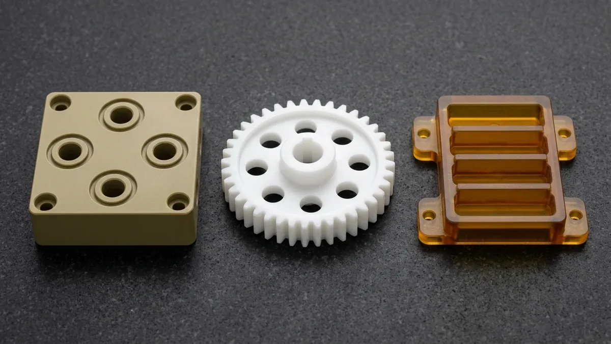
Holding burr-free edges on thermoplastics requires high-rake polished carbide tooling and chilled-air cooling (as shown in the CNC-machined engineering plastic parts below). Notice the spotfaced ports and concentric sealing grooves on the natural PEEK manifold, the involute teeth and keyway bore on the white POM-C spur gear, and the milled isolation channels on the amber Ultem 1000 insulator:
Polymer Machining Physics, Stress Annealing & Optical Polishing
Machining high-temperature polymers like Ultem (PEI) and PEEK or low-friction POM-C and Delrin acetal requires vacuum chucks or contoured soft jaws to prevent localized clamping indentation. For polyolefins, see our HDPE CNC machining and chip-control guide to prevent stringy ribbon wrapping.
Optical polymers follow strict post-processing separation: CNC machined PMMA acrylic undergoes 70–80 °C stress-relief annealing followed by #800–#5000 wet sanding and diamond-paste buffing (SPI A-1) or Single-Point Diamond Turning (SPDT)—never flame polishing or aggressive solvent vapor. Conversely, molded or machined polycarbonate (PC) is annealed at 110–120 °C before Dichloromethane (DCM) vapor polishing.
Carbon Fiber Composites, Laminates & Technical Ceramics
Fiber-reinforced thermoset composites and technical ceramics solve extreme engineering challenges where metals fail—delivering ultra-high specific stiffness in UAV airframes, >30 kV/mm dielectric insulation in high-voltage switchgear, and 1,650 °C refractory stability in semiconductor plasma chambers. Because cured carbon/glass fibers and sintered oxide ceramics are highly abrasive, they require specialized diamond tooling and dust-controlled machining cells.
| Material Grade | Density (g/cm³) & Strength / Hardness | Elastic Modulus (GPa) & Thermal / Dielectric Spec | Machining / Grinding Method & Tolerance (mm) | Recommended Application / When to Choose |
|---|---|---|---|---|
| 3K Twill / Plain Weave Carbon Fiber (CFRP) | 1.55–1.60 g/cm³ | Tensile: 600–900 MPa (87–130 ksi, quasi-isotropic plate) | E: 65–85 GPa | CTE: ~0.5–2.0 × 10⁻⁶ / K | Electrically conductive | PCD / diamond-cut compression burrs at 18,000–24,000 RPM | ±0.05 mm (±0.0020″) | UAV airframe plates, robotic end-of-arm tooling, and radiolucent medical C-arm plates; avoid unsealed contact with bare aluminum (galvanic corrosion). |
| G10 / FR4 Epoxy Glass Laminate | 1.85 g/cm³ | Flexural: 380–450 MPa (55–65 ksi) | E: 20–24 GPa | Dielectric: >30 kV/mm | FR4 is UL94 V-0 rated | Diamond-coated carbide end mills with vacuum extraction | ±0.03 mm (±0.0012″) | High-voltage transformer terminal boards, PCB wave-solder pallets, battery pack busbar barriers, and cryogenic thermal standoffs. |
| Alumina (Al2O3, 96%–99.5% Purity) | 3.85–3.92 g/cm³ | Flexural: 350–400 MPa | 1,500–1,650 HV (ASTM E384) | E: 370–380 GPa | Max Temp: 1,650 °C | Thermal: 25–30 W/m·K | Diamond wheel surface/cylindrical grinding & ultrasonic drilling | ±0.005 mm (±0.0002″) | Semiconductor plasma focus rings, high-voltage vacuum feedthroughs, and wear-resistant metering plungers; avoid tensile shock impact. |
| Yttria-Stabilized Zirconia (ZrO2, Y-TZP) | 6.05 g/cm³ | Flexural: 950–1,200 MPa | 1,250–1,350 HV | K_IC: 8–10 MPa·m½ | E: 205–210 GPa | CTE: 10.5 × 10⁻⁶ / K (matches steel) | Thermal: 2.5 W/m·K | Precision diamond creep-feed grinding & lapping | ±0.005 mm (±0.0002″), Ra 0.1 µm | Highest fracture-toughness ceramic for optical fiber ferrules, non-magnetic ball bearings, hot-extrusion dies, and medical shear blades. |
| Macor Machinable Glass Ceramic | 2.52 g/cm³ | Flexural: 94 MPa (13.6 ksi) | Compressive: 345 MPa | 250 HV | E: 66.9 GPa | Continuous 800 °C (Peak 1,000 °C) | Zero porosity / zero outgassing | Direct CNC milling, turning & tapping with carbide at Vc ≈ 30–50 m/min | ±0.013 mm (±0.0005″) | Fast-turnaround ultra-high-vacuum coil bobbins, laser spacers, and aerospace thermal insulators needing zero post-machining firing shrinkage. |
| Aluminum Nitride (AlN) | 3.26 g/cm³ | Flexural: 300–350 MPa | 1,100–1,200 HV | E: 320 GPa | Thermal Conductivity: 170–200 W/m·K | CTE: 4.5 × 10⁻⁶ / K | Diamond grinding & lapping | Flatness ≤ 0.005 mm | ±0.005 mm (±0.0002″) | High-power RF/IGBT semiconductor heat spreaders and electrostatic chuck heaters requiring both electrical insulation (>10¹³ Ω·cm) and aluminum-class heat dissipation. |
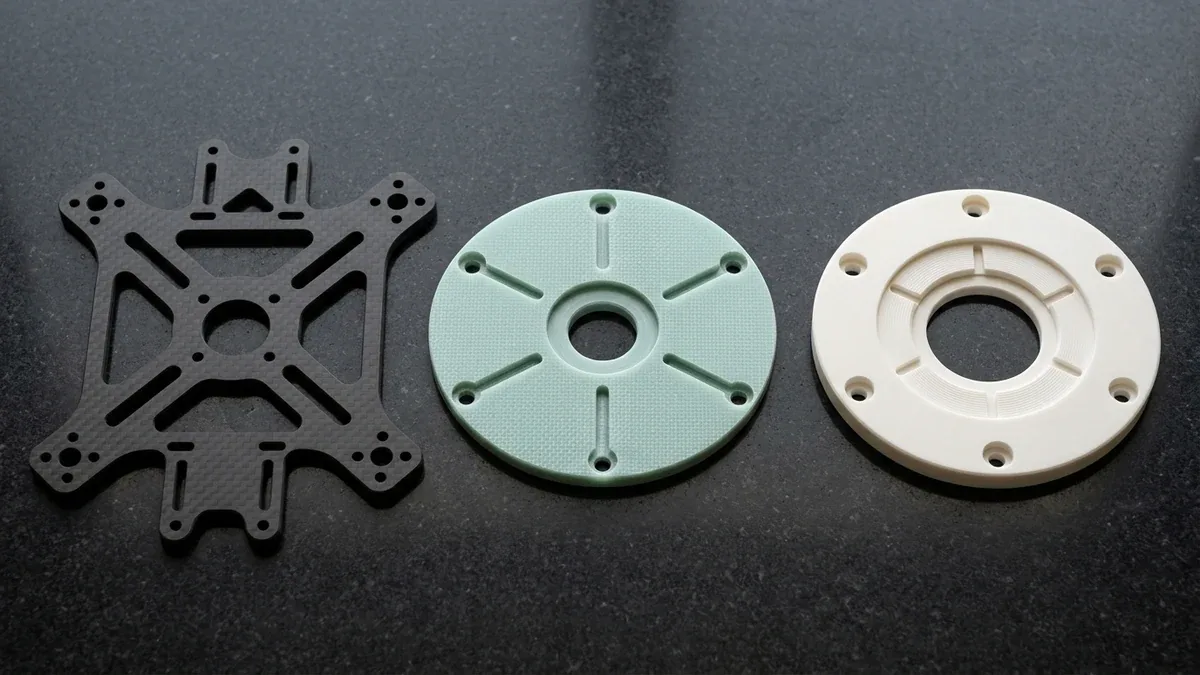
Preventing laminate fraying and ceramic micro-chipping requires diamond tooling and rigid backing fixtures (as shown in the machined composite and ceramic parts below). Compare the radiused truss cutouts on the 4.0 mm 3K twill CFRP drone plate, the radial isolation slots in the aqua-green G10/FR4 disk, and the stepped inner seat on the sintered alumina (Al2O3) wafer ring:
Delamination-Free Composite Routing & Ceramic Diamond Grinding
Standard high-helix metal end mills pull upward on top carbon plies, causing peel-up delamination. As detailed in our CFRP, GFRP, and FR4 composite machining guide, we run Polycrystalline Diamond (PCD) compression routers and diamond-cut burr tools at 18,000–24,000 RPM with sacrificial phenolic backing plates.
For fully sintered Alumina (Al2O3), Zirconia (ZrO2), and Aluminum Nitride (AlN), conventional cutting tools cannot shear the 1,100–1,650 HV crystal lattice. Our technical ceramic CNC machining and diamond grinding cell utilizes resin-bonded diamond wheels on Okamoto precision surface and cylindrical grinders to hold ±0.005 mm (±0.0002″) without subsurface micro-cracking.
Elastomers, Vacuum Casting Resins & Industrial 3D Printing Materials
When part geometries require Shore A elastomeric sealing, 10–100 unit bridge production without hard steel tooling, or internal additive lattices, we route builds across liquid silicone molding, polyurethane vacuum casting, and industrial 3D printing services. Understanding Shore hardness scales (ASTM D2240 / ISO 868), silicone mold life (15–25 shots per cavity), and Z-axis layer anisotropy prevents premature field failure:
| Material Category & Grade | Process Platform | Hardness / Tensile Strength & Elongation | Thermal Limit & Dimensional Standard | Recommended Application / When to Choose |
|---|---|---|---|---|
| Liquid Silicone Rubber (LSR, Platinum-Cured) | Liquid Injection Molding (LIM) in hardened S136 steel molds | Shore 10A–80A | Tensile: 7–11 MPa | Elongation: 300%–700% | −50 °C to +200 °C | ISO 3302-1 Class M1/M2 (flash ≤ 0.003 mm) | Medical respiratory masks, biocompatible valves (ISO 10993 / USP Class VI raw LSR), and IP68 optical seals. |
| TPU, EPDM & FKM (Viton) Elastomers | Injection / Overmolding, Compression Molding & Selective Laser Sintering | TPU: 60A–64D | EPDM: 50A–80A | FKM Viton: 70A–75A | Tensile: 10–35 MPa | TPU: 80 °C | EPDM: 150 °C | FKM: 200 °C | ISO 3302-1 / AS568 | TPU for abrasion-resistant cable boots and 2K grips; EPDM for outdoor UV/weather gaskets; FKM Viton for fuel and hydraulic oil O-rings. |
| PU Vacuum Casting Resins (ABS-like, PC-like, Rubber-like) | RTV-2 Silicone Molds under Vacuum (15–25 shots/mold) | ABS-like (UP4280/PX223): 55–65 MPa | Clear PC/PMMA-like (PX5210) | Rubber: Shore 30A–90A | HDT: 65–120 °C | ±0.15% (min ±0.15 mm) | Bridge batches of 10–100 cosmetic enclosures, clear lenses, or overmolded soft-grip prototypes before investing in production steel molds. |
| SLA Photopolymers (Standard, Tough, Clear, High-Temp) | 355 nm UV Laser Stereolithography (SLA) (0.05–0.10 mm layers) | Tensile: 45–68 MPa | Modulus: 2.2–2.8 GPa | Elongation: 6%–15% | HDT: 50–65 °C (Standard) / 238 °C (High-Temp) | ±0.10 mm or ±0.15% | High-detail master patterns, clear microfluidic visual prototypes (wet-sanded #800–#2000 + UV clear coat), and ergonomic housings; avoid outdoor UV load. |
| SLS Nylon PA12 & PA12-GF (Glass-Filled) | CO2 Laser Powder Bed Fusion Selective Laser Sintering (SLS) | PA12: 48 MPa, E = 1.7 GPa, 18% elong. | PA12-GF: 51 MPa, E = 3.2 GPa | HDT: 85–115 °C (PA12) / 155 °C (PA12-GF) | ±0.20 mm or ±0.20% | Support-free functional snap-fit enclosures, complex air ducts, and living hinges; PA12-GF adds stiffness and thermal resistance. |
| HP Multi Jet Fusion (MJF) PA12 | Thermal Inkjet Fusing Agent Multi Jet Fusion (MJF) (0.08 mm voxel) | Tensile: 48–50 MPa (near-isotropic XY/Z) | Modulus: 1.8 GPa | 15%–20% elong. | HDT: 95–110 °C | ±0.15–±0.20 mm | Vapor-smoothed Ra 1.2 µm | Low-volume production brackets, robotics covers, and fluid-tight nylon manifolds requiring higher Z-axis strength and denser walls than SLS. |
| Industrial FDM (Ultem 9085 & ABS-M30) | Heated-Chamber Industrial Fused Deposition Modeling (FDM) | Ultem 9085: 69 MPa (XY), E = 2.2 GPa | ABS-M30: 32 MPa (XY), E = 2.4 GPa | HDT: 153 °C (Ultem 9085, UL94 V-0 FST) / 96 °C (ABS-M30) | ±0.15–±0.25 mm | Ultem 9085 for aerospace ducts and composite layup tooling; ABS-M30 for shop-floor assembly jigs; account for 30%–45% Z-axis layer strength derating. |
| DMLS Metal Powders (Ti64, 316L, AlSi10Mg, MS1 Maraging Steel, Inconel 718) | Fiber-Laser Powder Bed Direct Metal Laser Sintering (DMLS) | 99.5%+ density | Ti64: 1,050 MPa | MS1 aged: 1,950 MPa (50–54 HRC) | Inconel 718: 1,100 MPa | Inconel 718 up to 650 °C | ±0.10–±0.20 mm as-built / ±0.010 mm CNC post-milled | Topology-optimized aerospace brackets, MS1 mold inserts with conformal cooling channels, and Inconel 718 turbine nozzles (add +0.5–1.0 mm stock on mating datums for CNC finish milling). |
Cross-Family Functional Part Portfolio
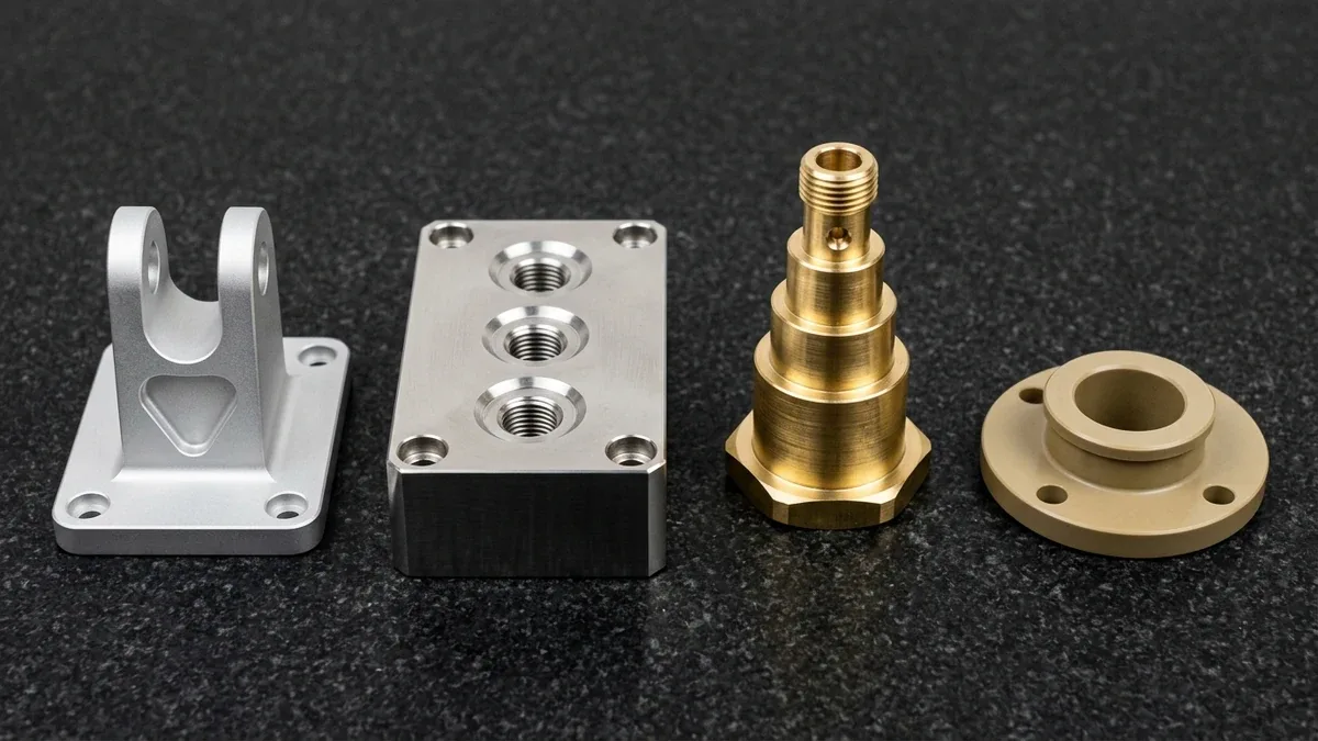
Multi-Material BOMsShown: a bead-blasted 7075-T651 aluminum clevis bracket, a 316L stainless steel fluid valve manifold, a C3604 brass stepped fitting, and a virgin PEEK bearing bushing inspected on black granite.
- Single-Source Fit-Up: Mating metal shafts, polymer bushings, and elastomer seals are trial-assembled against shared GD&T datums before dispatch.
- Master Pattern Accuracy: CNC-machined or SLA and SLS 3D printed master patterns drive 15–25 bubble-free urethane castings per RTV-2 silicone mold.
Elastomer, Casting & Additive Design Rules
Shore A · PU · DMLSMatch durometer hardness, mold shrinkage, and post-machining stock allowances to your functional test conditions across urethane vacuum casting and elastomer molding:
- O-Ring & Seal Compression (AS568): Design static elastomer glands for 15%–25% compression (10%–18% dynamic) and 65%–85% groove fill.
- Injection Draft & VDI 3400 Texture: Provide 0.5°–1.0° draft on polished cores, adding +1.0°–1.5° per 0.025 mm (0.001″) of texture depth (1.5°–2.0° for VDI 24; 2.5°–3.0° for VDI 30).
- Uniform Polymer Wall Thickness: Keep molded plastic ribs at 40%–60% of nominal wall thickness to eliminate sink marks and weld lines.
- Hybrid DMLS + CNC Machining: Add +0.5–1.0 mm stock on critical DMLS metal bearing seats and sealing faces for post-build 3/5-axis CNC finish milling to ±0.010 mm.
How Do You Select and Verify Materials Across Processes?
Selecting the optimal material and manufacturing route requires balancing batch quantity, wall-thickness geometry, isotropic load requirements, and ex-factory turnaround time. While 3D printing and vacuum casting eliminate hard tooling upfront, subtractive CNC machining and precision sheet metal fabrication provide wrought metallurgical properties from unit one:
| Manufacturing Process | Raw Material Stock Form & Isotropy | Economic Volume & Tooling Setup | Standard & Critical Tolerances | Ex-Factory Production Turnaround | Recommended Application / When to Choose |
|---|---|---|---|---|---|
| 3/4/5-Axis CNC Milling & Turning | Wrought metal billets, stretched plates & extruded polymer rods (100% isotropic) | 1–1,000+ pcs | Near Zero (Direct CAD CAM & soft-jaw setup) | ISO 2768-mK general | ±0.010–±0.020 mm (±0.0004″–±0.0008″) critical fits | 4–8 Business Days (raw) | 7–12 Days (finished) | 7–30 Days (10–1,000+ batch) | Functional structural brackets, manifolds, shafts, and tight-tolerance bearing housings requiring true wrought material properties. |
| Wire EDM & Precision Grinding | Hardened tool steels (D2, S136, H13, 440C), carbide & sintered ceramics | 1–500+ pcs | Low (Electrode / wheel dressing setup) | ±0.005 mm (±0.0002″) | Ra 0.2–0.4 µm (8–16 µin) | 5–10 Business Days ex-factory | Hardened mold inserts, sharp internal keyways, stamping punches, and diamond-ground Alumina or Zirconia wear sleeves. |
| Sheet Metal Laser & CNC Bending | Cold-rolled gauge sheet (5052-H32, 6061-T6, 304/316L, CRS/SPCC, C11000) | 1–5,000+ pcs | Near Zero (Standard Amada press-brake V-dies) | Laser cut & hole pitch: ±0.10–±0.20 mm (ISO 2768-m) | Bend: ±0.20–±0.40 mm, ±0.5°–±1.0° | 4–8 Business Days (raw) | 7–12 Business Days (powder coated / plated) | Uniform-wall electronics chassis, server racks, battery trays, and PEM-nut brackets; see our sheet metal forming and K-factor guide. |
| Rapid Tooling & Injection Molding | Production thermoplastic pellets (ABS, PC, POM, PA66-GF30, PEEK, PP) & LSR | 100–100,000+ pcs | Low / Moderate Tooling Investment (P20, NAK80, S136, H13) | ISO 20457 / DIN 16742 (thermoplastics) | ISO 3302-1 (LSR/elastomers) | 12–18 Business Days (simple T1 rapid mold) | 18–35 Days (complex steel mold & production) | DVT/PVT validation and scale production requiring authentic resin pellets, VDI 3400 textures, insert molding, or 2K overmolding. |
| Polyurethane Vacuum Casting | Two-part thermoset PU resins (ABS-like, PC-like, Rubber-like Shore 30A–90A) | 10–100 pcs | Very Low (RTV-2 silicone mold from SLA/CNC master, 15–25 shots) | ±0.15% (min ±0.15 mm) | 7–12 Business Days ex-factory | Bridge-to-tooling pilot runs, market-testing enclosures, and multi-durometer elastomers without committing to steel mold NRE. |
| Industrial 3D Printing (SLA/SLS/MJF/FDM/DMLS) | Photopolymers, PA12/PA12-GF powders, Ultem 9085 filament & DMLS metal powders | 1–200 pcs | Near Zero (Direct CAD build setup) | ±0.10–±0.20 mm as-printed | ±0.010 mm on hybrid CNC post-machined DMLS datums | 4–8 Business Days ex-factory | Organic lattices, internal conformal cooling channels, and rapid form/fit iterations impossible to reach with subtractive cutters. |
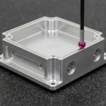
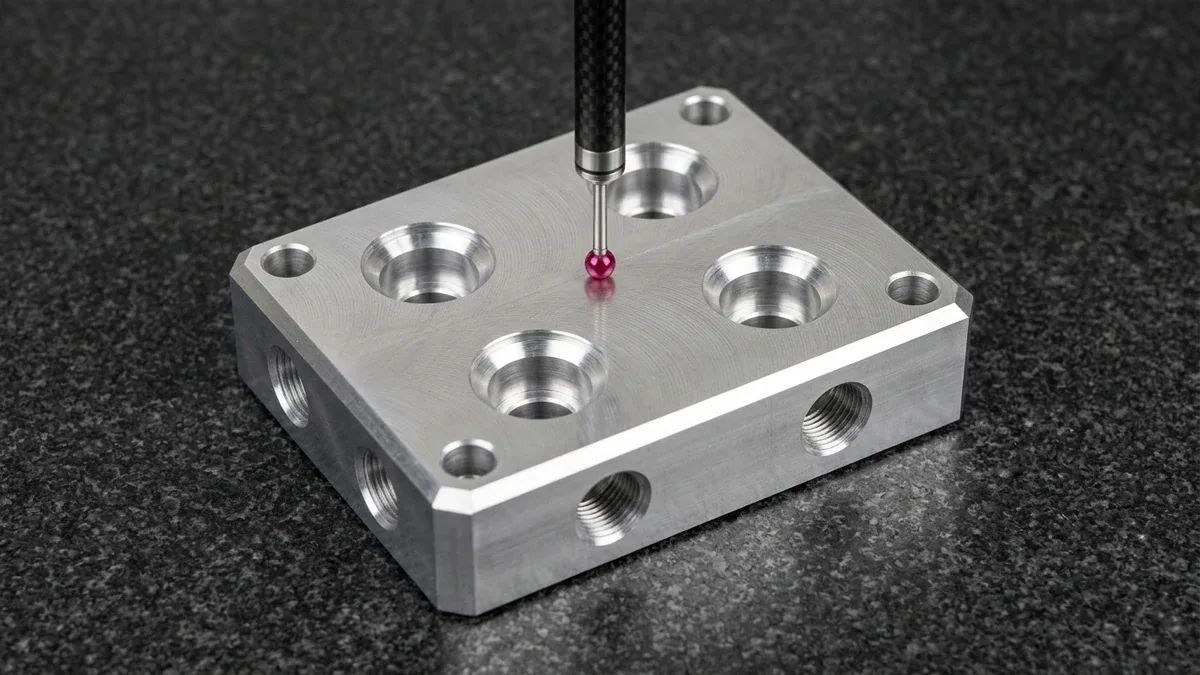
Every incoming billet, sheet, and resin lot passes a four-stage verification protocol before spindle release and final metrology inspection (as shown in the granite CMM datum setup below). Observe the vertical bridge CMM spherical ruby stylus probing the flat top datum face of a bare-metal 7075-T651 aluminum hydraulic manifold with four stepped cylindrical valve cavities:
Incoming Alloy Verification & Stress-Distortion Control
Shop-Floor Rule of Thumb: In our in-house CNC machining facility, when roughing asymmetric pockets removing >60% stock volume from 250 mm long aluminum plates, we mandate 6061-T651 pre-stretched rolled plate and alternating Flip-Flop roughing passes to balance internal stress release.
Troubleshooting Bowing (Symptom → Root Cause → Corrective Action): Symptom: A 250 × 80 × 12 mm housing bowed 0.18 mm after vise release. Root Cause: Extruded 6061-T6 flat bar retained cold-drawn skin stress. Corrective Action: Switch stock to 6061-T651 plate, anneal rough blanks at 155 °C × 3 h with 0.5 mm stock allowance, and finish on vacuum fixtures to hold ⏥ 0.02 mm flatness.
Audit Mill Test Reports
Engineers cross-check Mill Test Report (MTR) heat-lot chemistry, temper condition, and tensile yield certificates against ASTM, AMS, or DIN drawing callouts.
XRF / OES Alloy Scan
Every incoming bar and plate is scanned via handheld X-Ray Fluorescence (XRF) or Optical Emission Spectroscopy (OES) to prevent 304 vs. 316L or 6061 vs. 7075 mix-ups.
ASTM Hardness Screening
Heat-treated metals are tested per ASTM E18 (Rockwell HRC/HRB) and ASTM E384 (Vickers HV), while elastomers and plastics are checked via ASTM D2240 / ISO 868 durometers.
20 °C ± 1 °C Metrology
Finished parts stabilize in our 20 °C ± 1 °C lab before Zeiss CMM probing, 2.5D Optical VMS scanning, and ISO 4287 surface roughness verification.
Material Stiffness, Thin-Wall Cutting Deflection & Shop-Floor Control
Material elastic modulus (E) and specific cutting pressure (kc) directly govern the thinnest wall we can machine without elastic push-away. Linear thermal expansion drift (ΔL = α · L · ΔT) is detailed in our aluminum residual stress and thermal deformation guide, and end-mill overhang deflection (δ ∝ L³/D⁴) is covered in our internal corner radius and tool deflection guide.
Workpiece Thin-Wall Elastic Springback (δ_wall)
Cantilever MechanicsIllustrative benchmark for finishing a vertical wall of thickness t = 2.0 mm (0.079″), unsupported height H = 12.0 mm (0.472″), and active contact width b = 6.0 mm (0.236″) to hold ±0.020 mm (±0.0008″):
- Engagement Input: Axial depth ap = 2.0 mm, mean chip thickness hm = 0.015 mm, chip area A_chip = ap × hm = 0.030 mm², and radial passive thrust ratio η_r = Fr / Fc = 0.35.
- Section Compliance: Wall moment of inertia I_wall = (b × t³) ÷ 12 = (6.0 × 8.0) ÷ 12 = 4.00 mm⁴; geometric compliance factor K_geom = H³ ÷ (3 × I_wall) = 1,728 ÷ 12.0 = 144.0 mm⁻¹.
- Deflection Formula: Tangential force Fc = kc × A_chip, radial thrust Fr = 0.35 × Fc, and top-edge wall deflection δ_wall = (Fr × H³) ÷ (3 × E × I_wall) = (144.0 × Fr) ÷ E.
- Shop-Floor Countermeasure: When δ_wall approaches the ±0.020 mm limit, our CAM team steps down in 1.0 mm waterline passes, adds a zero-offset spring pass, or supports thin polymer walls with urethane nesting plugs.
1. 6061-T651 Aluminum (E = 68.9 GPa, kc = 750 N/mm²)
δ_wall = 0.0165 mm (PASS)Specific stiffness E/ρ = 25.52 GPa·cm³/g. Cutting force Fc = 22.50 N and radial thrust Fr = 7.875 N produce δ_wall = (144.0 × 7.875) ÷ 68,900 = 0.0165 mm (16.5 µm), holding ±0.020 mm in a single finishing pass.
2. PEEK-CF30 Carbon-Filled (E = 22.0 GPa, kc = 280 N/mm²)
δ_wall = 0.0192 mm (PASS)Specific stiffness E/ρ = 15.71 GPa·cm³/g. Fc = 8.40 N and Fr = 2.940 N yield δ_wall = (144.0 × 2.940) ÷ 22,000 = 0.0192 mm (19.2 µm), cutting polymer wall deflection by 76.9% versus unfilled PEEK.
3. Ti-6Al-4V Grade 5 (E = 113.8 GPa, kc = 1,950 N/mm²)
δ_wall = 0.0259 mm (Spring Pass)High cutting pressure generates Fc = 58.50 N and Fr = 20.475 N, pushing δ_wall to (144.0 × 20.475) ÷ 113,800 = 0.0259 mm (25.9 µm) (+29.5% over ±0.020 mm); requires 1.0 mm waterline step-downs or t ≥ 2.2 mm.
4. Unfilled PEEK 450G (E = 4.0 GPa, kc = 220 N/mm²)
δ_wall = 0.0832 mm (5.05× Al)Low elastic modulus causes Fc = 6.60 N and Fr = 2.310 N to deflect the wall by (144.0 × 2.310) ÷ 4,000 = 0.0832 mm (83.2 µm) (4.16× over limit); thicken walls to t ≥ 3.0 mm or upgrade to PEEK-CF30.
Material-to-Surface Finish Compatibility & Dimensional Growth Rules
Post-machining surface finishes and protective coatings alter surface hardness, corrosion resistance, electrical conductivity, and final bore dimensions. As established in our aluminum anodizing specification guide, anodic oxide grows 50% inward into the substrate and 50% outward, whereas ASTM A967 stainless steel passivation removes free iron with ~0.002 µm zero dimensional buildup:
| Surface Finish & Standard | Compatible Base Materials | Total Film Thickness & Outward Growth per Side | Surface Hardness / Salt Spray (ASTM B117) | Recommended Application / Masking Rule |
|---|---|---|---|---|
| Anodizing Type II (MIL-A-8625 Type II) | Aluminum 6061-T6, 6061-T651, 7075-T651, 5052-H32, 6063-T5 (avoid high-Si ADC12 for clear/bright colors) | 10–25 µm total | +5 to +12.5 µm outward growth per side | 300–350 HV0.05 | 168–240h neutral salt spray | Electrically insulating | Cosmetic and corrosion-resistant housings in clear, black, blue, red, or gold; mask H7 bores (+0/+IT7) and ≤ ±0.015 mm dowel holes with silicone plugs. |
| Hardcoat Anodizing Type III (MIL-A-8625 Type III) | Aluminum 6061-T6, 6061-T651, 7075-T651 | 50 µm total | +25 µm outward per side (bores shrink ~0.05 mm, ODs grow ~0.05 mm) | 450–550 HV0.05 (ASTM E384) | 240h+ ASTM B117 | Sliding wear rails, pneumatic cylinders, and subsea ROV housings; pre-machine precision bores +0.05 mm oversize or mask critical threads and fits. |
| Chromate Conversion (Alodine 1200S / SurTec 650) | All Aluminum alloys (6061, 7075, 2024, ADC12) & Magnesium (AZ31B, AZ91D) | 0.5–1.5 µm | Negligible dimensional change (~0 µm) | 168h ASTM B117 | Electrically conductive (RoHS / REACH trivalent SurTec 650) | EMI/RFI grounding flanges, RF chassis, and paint primer base; zero masking needed on standard threads or bores. |
| Citric / Nitric Passivation (ASTM A967 / AMS 2700) & Electropolishing (ASTM B912) | Stainless Steels (303, 304, 316L, 17-4PH, 440C, 416) | Passivation: ~0.002 µm (zero growth) | Electropolishing: removes 5–15 µm per side | 96–240h ASTM B117 | Electropolishing halves Ra roughness | Passivation is mandatory for surgical, food, and marine stainless parts (no masking required); electropolishing for ultra-clean semiconductor tubing. |
| Electroless Nickel (ENP), Hard Chrome & PVD (TiN / DLC) | Alloy/Carbon Steels (4140, 1045), Tool Steels (D2, H13, S136), Aluminum, Copper/Brass | ENP: +5 to +25 µm uniform | Hard Chrome: +10 to +50 µm | PVD: +1 to +4 µm | ENP: 500–850 HV | Hard Chrome: 800–1,000 HV | PVD DLC: 1,500–2,500 HV | ENP for uniform corrosion protection on complex internal steel manifolds; Hard Chrome for ground shafts; PVD TiN/DLC for mold cores and medical wear parts. |
| Optical Polymer Polishing (SPDT / Diamond Buffing vs. DCM Vapor vs. UV Clear Coat) | PMMA Acrylic, PC Polycarbonate, Clear SLA & Clear PU Cast Resins | Mechanical / SPDT: −5 to −15 µm | DCM Vapor: ~0 µm | UV Clear Coat: +15 to +30 µm | Ra 0.02–0.05 µm (SPI A-1 optical clarity, 88%–92% transmission) | PMMA: 70–80 °C anneal + #800–#5000 wet sand & diamond buffing or SPDT (never flame or DCM vapor); PC: 110–120 °C anneal + DCM vapor; SLA/PU: #800–#2000 sand + UV clear coat. |
Cost-Driven Prismatic Hardware
Default to 6061-T651 aluminum for milled brackets/enclosures, 5052-H32 for bent sheet metal chassis, and POM-C or ABS for general plastic components to maximize cutting speed and minimize unit cost.
High-Stress & Fatigue Assemblies
Specify 7075-T651 or Ti-6Al-4V Grade 5 for aerospace strength-to-weight, 17-4PH H900 for corrosion-resistant high torque, and 4140 / 4340 Q&T or D2 / S136 for high-contact-stress shafts and dies.
Thermal, Chemical & Medical
Choose 316L stainless (passivated per ASTM A967) for marine chloride, PEEK / PPSU / Ultem 1000 for 134–250 °C sterilization and chemical resistance, and Alumina / AlN for >800 °C dielectric heat dissipation.
EVT Prototypes to PVT Production
Use CNC / SLA / SLS / MJF for 1–50 EVT units, transition to PU Vacuum Casting for 10–100 bridge units, and scale to P20/NAK80/S136 Injection Molding or H13 HPDC at 100–100,000+ units.
Metal & Alloy Machining Specifications
Non-Ferrous, Polymer, Composite & Ceramic Guides
Frequently Asked Questions (FAQ) About Manufacturing Materials
How do you verify incoming metal alloys and engineering plastics before machining?
Every raw metal batch undergoes Mill Test Report (MTR) chemical review, handheld X-ray fluorescence (XRF) alloy verification, and ASTM E18 Rockwell hardness screening upon arrival. Engineering plastics are verified against supplier resin certificates and conditioned before 20 °C ± 1 °C Zeiss CMM dimensional inspection.
When should I specify 6061-T651 rolled plate instead of 7075-T651 aluminum?
Select 6061-T651 aluminum for general structural brackets, welded assemblies, and decorative MIL-A-8625 Type II anodized enclosures where 276 MPa (40.0 ksi) yield strength suffices. Upgrade to 7075-T651 at 503 MPa (73.0 ksi) yield strength only for high-load aerospace fittings, robotic links, and non-welded precision mechanisms.
Which engineering plastic holds the tightest CNC machining tolerances without moisture swelling?
Acetal copolymer (POM-C) and glass-filled PEEK hold the tightest CNC machining tolerances down to ±0.015 mm (±0.0006″) because moisture absorption stays below 0.25%. Avoid unfilled Nylon PA6 or PA66 for humid precision fits, as 1.5%–2.8% water uptake causes +0.3%–0.6% dimensional expansion after machining.
What are the standard tolerances and ex-factory lead times across different materials?
CNC machined metals and rigid plastics follow ISO 2768-mK with critical features held to ±0.010–±0.020 mm (±0.0004″–±0.0008″), while molded plastics follow ISO 20457. Ex-factory turnaround is 4–8 business days for raw prototypes and 7–12 business days for anodized or plated components, excluding 3–5 days air transit.
Need Engineering Material Selection & Custom Part Quoting?
Uncertain about alloy machinability, post-machining heat treatment, or polymer moisture stability? Upload your 3D CAD models (STEP/IGES) and 2D tolerance drawings for a complimentary DFM review, traceable MTR material verification, and custom production quotation.
Upload CAD for Material DFM & Custom Quote →