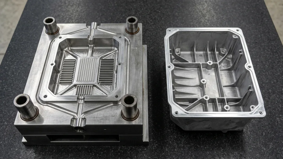
High volume manufacturing demands rapid cycle times, high dimensional repeatability, and exceptional surface fidelity. Therefore, high pressure die casting serves as the primary metal forming foundation for modern powertrain and electronics hardware. By injecting molten non-ferrous alloys under intense hydraulic pressure, engineers produce intricate thin-walled metal components efficiently. Consequently, high pressure die casting outpaces conventional sand casting and investment casting in production speed.
However, successful high pressure die casting requires deep mastery of thermal management, runner design, and alloy solidification. Improper gate geometry or incorrect shot velocity causes turbulent gas entrapment and costly porosity defects. Conversely, optimized tool cooling lines and rigorous process controls guarantee structural integrity. In this engineering guide, we examine machine configurations, alloy selection, tooling steels, and critical DFM rules.
- Core Focus & DFM Scope: Actionable shop-floor engineering guidelines for High Pressure Die Casting, covering material selection, geometric tolerancing, and defect prevention.
- Dimensional Tolerance Baseline: General molded/cast features hold ISO 2768-mK or ±0.05 to ±0.10 mm (±0.002″ to ±0.004″); critical post-machined datum bores achieve ±0.010 mm (±0.0004″).
- Tooling & Surface Integrity: Cavity surfaces finished from SPI A-2 mirror polish (Ra 0.05 µm / 2 µin) to VDI 3400 spark-eroded textures with mandatory 1.0°–2.5° draft angle compensation.
- Metrology & Flow Validation: Pre-tooling DFM and rheological fill simulation paired with Zeiss CMM first-article inspection (FAI) and wall-thickness ultrasonic/section verification.
- Ex-Factory Turnaround: 7 to 12 business days for vacuum cast/urethane bridge batches; 18 to 35 business days for rapid aluminum/P20/H13 tooling and T1 sample delivery (excluding 3–5 days air transit).
1. Fundamental Mechanics: Cold Chamber vs Hot Chamber Die Casting
High pressure die casting systems operate using either cold chamber or hot chamber architectures. Cold chamber casting machines isolate the melting furnace from the injection mechanism. Molten metal is ladled into an unheated shot sleeve before a hydraulic plunger forces it forward. Consequently, cold chamber machines process high-melting alloys such as aluminum and magnesium without degrading machine components.
In contrast, hot chamber die casting submerges the injection cylinder directly into the molten metal crucible. A specialized gooseneck channel feeds molten alloy straight into the die cavity during every cycle. Therefore, hot chamber casting achieves faster cycle rates and eliminates manual pouring operations. However, the continuous thermal exposure limits hot chamber machines to low-melting zinc and lead alloys.
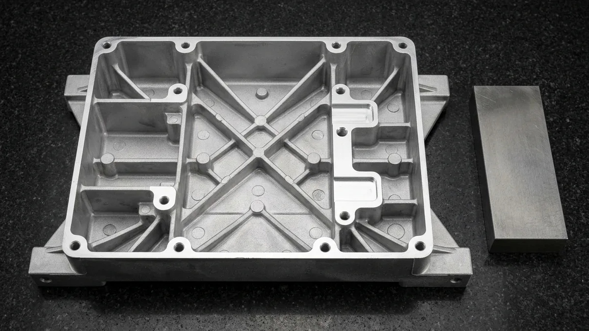
2. Cold Chamber vs Hot Chamber Process Comparison
Selecting the optimal casting architecture depends on annual part quantities, alloy melting points, and wall thickness. Engineering teams evaluate clamping tonnage and pressure dynamics to size casting machinery accurately. The technical matrix below compares operational parameters across both casting methodologies.
| Operational Parameter | Cold Chamber Casting | Hot Chamber Casting | Engineering Recommendation |
|---|---|---|---|
| Applicable Alloys | Aluminum (A380, ADC12), Brass, Magnesium | Zinc (Zamak 3, Zamak 5), Magnesium (limited) | Match alloy melt point to furnace configuration |
| Injection Pressure Range | 30 MPa to 120 MPa (4,350 to 17,400 psi) | 10 MPa to 35 MPa (1,450 to 5,000 psi) | Higher pressure required for thin aluminum sections |
| Typical Cycle Times | 20 to 60 seconds per shot | 3 to 15 seconds per shot | Hot chamber maximizes throughput on small zinc hardware |
| Tool Thermal Fatigue Risk | High due to thermal shock from aluminum | Moderate due to lower molten zinc temperatures | Use premium H13 or DIEVAR mold steels |
| Minimum Wall Thickness | 1.5 mm to 2.0 mm | 0.8 mm to 1.2 mm | Zinc enables thinner walls without premature freezing |
3. High Pressure Die Casting Alloys: Mechanical and Thermal Properties
Material selection governs tensile strength, thermal conductivity, corrosion resistance, and total production cost. Aluminum alloy A380 remains the worldwide standard for commercial die cast enclosures and housings. A380 offers excellent fluidity, good pressure tightness, and balanced mechanical strength. Additionally, Japanese specification ADC12 provides outstanding die-filling characteristics for thin cooling fins.
When high impact strength and mirror-level cosmetic finishing are required, Zamak 3 zinc alloy delivers superior results. Zinc flows exceptionally well into ultra-thin cross sections, allowing delicate snap features. Furthermore, magnesium AZ91D provides the highest strength-to-weight ratio among commercial casting alloys, supporting aerospace and lightweight electronics. Reviewing alloy mechanical properties ensures structural compliance under functional loads.
| Casting Alloy Grade | Tensile Strength (MPa) | Yield Strength (MPa) | Thermal Conductivity (W/m·K) | Primary Application Domain |
|---|---|---|---|---|
| Aluminum A380 | 324 | 160 | 96 | Automotive brackets, motor housings, electronic enclosures |
| Aluminum ADC12 | 310 | 150 | 96 | High-density heat sinks, telecom enclosures, transmission covers |
| Zinc Zamak 3 | 283 | 208 | 113 | Precision gears, electronic shielding, decorative luxury hardware |
| Magnesium AZ91D | 230 | 150 | 72 | Lightweight drone frames, power tool casings, steering columns |
4. Tooling Engineering: Mold Steels, Cooling, and Venting Systems
Die casting dies endure extreme thermal cycling, mechanical abrasion, and high hydraulic shock forces. Therefore, selecting premium hot-work tool steels determines production mold longevity. Premium AISI H13 tool steel tempered to forty-six to forty-eight HRC represents the standard core material. Furthermore, advanced ESR refined steels like DIEVAR minimize thermal checking and stress cracking over millions of cycles.
Equally critical is thermal management within the tool steel cavity. Inefficient cooling circuits cause localized hot spots, extending cycle times and inducing severe shrinkage porosity. Consequently, toolmakers design conformal cooling channels alongside high-conductivity beryllium copper chill pins. Meanwhile, chill vents and vacuum overflow blocks extract trapped air ahead of the advancing melt front.
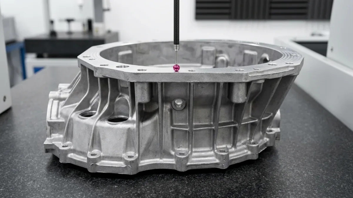
5. Critical DFM Rules for High Pressure Die Cast Components
Optimizing component geometry early saves substantial tooling rework and prevents recurring production defects. First, maintaining uniform wall thickness prevents uneven cooling rates and surface sink marks. When thickness transitions are unavoidable, gradual blended transitions reduce internal stress concentrations. Thin walls freeze rapidly, whereas thick sections demand longer dwell times.
Second, draft angles must be applied to all surfaces parallel to mold opening directions. For aluminum castings, outside walls require at least one degree of draft angle. Conversely, interior core pins require two degrees of draft to facilitate smooth part ejection. In addition, generous fillet radii throughout all internal corners promote smooth laminar metal flow during shot injection.
Finally, integrating secondary CNC machining allowances guarantees precision on critical bearing fits. Die cast surfaces comfortably maintain ISO 2768-mK tolerances in as-cast conditions. However, tight bearing bores require plus or minus 0.01 mm tolerances achieved through secondary milling. You can explore our precision capabilities in rapid tooling and mold manufacturing to optimize your production pipeline.
Moreover, our advanced production lines manufacture mission-critical structural castings for demanding industries. Discover how our engineering team delivers precision parts for automotive manufacturing components and high-reliability systems.
Why Do High Pressure Die Casting Projects Experience Dimensional Warpage or Flash, and How Do You Prevent It?
Managing High Pressure Die Casting successfully requires balancing volumetric shrinkage, cavity clamping pressure, and thermal dissipation across uneven wall cross-sections. While uniform walls of 1.5 to 3.0 mm (0.060″ to 0.118″) stabilize flow fronts within ±0.05 mm (±0.002″), abrupt rib-to-wall transitions exceeding a 0.6:1 ratio induce localized sink marks, internal voids, and residual warpage.
Shop-Floor Quantitative Derivation: Clamping Force, Shrinkage & Thermal Cooling Balance
In our Shenzhen tooling and molding engineering practice, preventing parting-line flash and dimensional drift in High Pressure Die Casting starts with exact clamping tonnage and linear shrinkage compensation before steel or aluminum blocks are cut. Consider a structural housing with a projected cavity area Aproj = 140 cm² (21.7 in²) molded at an internal cavity pressure Pcav = 45 MPa (6,525 psi):
Fclamp = Aproj × Pcav × Sf = 140 cm² × 0.45 kN/cm² × 1.20 = 75.6 tonnes (83.3 US tons)
Simultaneously, tooling cavity dimensions (Dcavity) must compensate for isotropic or anisotropic material shrinkage (S).
For a nominal 120.00 mm (4.7244″) datum spacing with a semi-crystalline or alloy shrinkage factor of S = 1.6% (0.016 mm/mm), the machined cavity steel dimension is calculated as Dcavity = Dnom × (1 + S) = 120.00 × 1.016 = 121.92 mm (4.8000″). To lock critical bearing bores or sealing faces within ±0.010 mm (±0.0004″), we leave a 0.40 mm (0.016″) stock allowance for post-molding 3-axis and 4-axis CNC finish milling.
Step-by-Step Shop-Floor Execution & Quality Protocol
To bridge CAD intent with repeatable shop-floor delivery, our engineering team enforces a four-stage execution workflow across every prototype and low-volume production batch:
- Step 1: Rheological Flow & Wall-Thickness DFM Audit: Analyze 3D CAD geometry (STEP/IGES) to verify uniform wall sections, apply 1.0° to 2.5° draft angles per VDI 3400 / SPI texture depth, and position gates away from cosmetic or high-stress zones.
- Step 2: Precision Cavity Machining & Venting Calibration: Machine P20, H13, S136, or 7075-T651 tooling inserts via high-speed CNC milling and Wire/Sinker EDM, grinding perimeter gas vents to 0.015–0.030 mm (0.0006″–0.0012″) depth to evacuate trapped air without flash.
- Step 3: Thermal Stabilization & Scientific Process Windowing: Stabilize mold tool temperature via turbulent conformal/baffle cooling channels (Reynolds number Re > 4,000) and decouple fill, pack, and hold stages to eliminate weld lines and internal porosity.
- Step 4: T1 First-Article Zeiss CMM & Section Verification: Inspect T1 shots after 24-hour thermal conditioning at 20°C (68°F) using Zeiss CMM probing and optical comparator overlays against ISO 2768-mK and drawing GD&T callouts.
Shop-Floor Defect Troubleshooting & Corrective Action Matrix
When evaluating part geometry during pre-production DFM review, our manufacturing engineers screen for the following failure modes and apply proven corrective controls:
| Defect / Symptom | Physical Root Cause | Shop-Floor Corrective Action | Recommended DFM Spec Limit |
|---|---|---|---|
| Parting-Line Flash / Burrs | Insufficient clamp tonnage, excessive injection velocity, or vent depth exceeding 0.04 mm (0.0016″) | Increase clamp safety factor to 1.25×, switch from velocity-to-pressure transfer at 98% fill, and lap parting faces to ≤0.010 mm (≤0.0004″) shutoff. | Flash ≤ 0.05 mm (0.002″) |
| Localized Sink Marks & Voids | Rib-to-wall thickness ratio exceeding 60% causing core thermal contraction after skin freeze | Coring out thick bosses, reducing rib root thickness to 50%–60% of nominal wall, and extending packing pressure until gate freeze-off. | Rib root = 0.5–0.6 × twall |
| Flow Weld / Knit Line Weakness | Converging melt/flow fronts cooling below fusion threshold around cored holes or inserts | Raise melt and mold surface temperatures by 15°C–25°C (27°F–45°F), add overflow wells at knit zones, and relocate gate entry vectors. | Tensile retention ≥ 85% |
| Post-Ejection Warpage & Twist | Differential cooling across asymmetric cavity halves or fiber orientation anisotropy | Balance core/cavity coolant delta within ΔT ≤ 5°C (9°F), anneal stressed parts in precision cooling jigs, and post-machine critical datums. | Flatness ≤ 0.10 mm / 100 mm |
Engineering Trade-Offs: When NOT to Over-Specify
When to Avoid This Process (Engineering Limitations): Do not specify dedicated hard tooling or molding workflows when unit quantities are under 10 pieces and the design geometry is still undergoing weekly functional revisions. In early-stage validation where upfront tooling amortization and 18 to 35 business days of tool fabrication delay testing, direct high-speed 3-axis and 4-axis CNC machining from solid engineering billet or polyurethane vacuum casting (4 to 12 business days ex-factory) delivers superior agility with zero steel modification risk.
🔗 Related Shop-Floor Engineering Guides & Cross-Process Benchmarks:
When validating High Pressure Die Casting before committing to multi-slide H13 production dies, hardware teams frequently machine functional pre-production housings from billet or utilize bridge tooling. Compare our Aluminum Rapid Tooling vs. Steel Tooling DFM Guide for bridge volume economics, and review our Aluminum Machining Dimensional Stability Guide for post-casting CNC datum milling tolerances (±0.010 mm / ±0.0004″) verified on Zeiss CMM inspection systems.
High pressure die casting injects molten metal under hydraulic pressures exceeding 30 to 100 MPa into hardened steel dies. Consequently, this process delivers ultra-fast cycle times, thinner wall sections, and superior dimensional repeatability. Conversely, gravity die casting relies solely on natural hydrostatic gravity pressure to fill permanent molds. Therefore, gravity casting produces thicker parts at lower production volumes with lower tooling investment.
Standard die castings require secondary machining stock allowances between 0.5 mm and 1.5 mm on critical gasket surfaces. Furthermore, bearing journals and threaded holes require dedicated machining allowances. However, applying excessive machining stock cuts through the dense, fine-grained surface skin into porous core areas. Consequently, deep machining passes reduce local mechanical strength and pressure tightness.
Vacuum-assisted die casting evacuates air and lubricating gas from sealed mold cavities before molten metal advances. Specifically, high-capacity vacuum valves drop cavity pressure below 50 millibars within milliseconds. Consequently, eliminating trapped cavity gas prevents internal porosity during rapid shot advancement. Furthermore, dense vacuum-cast parts can undergo post-casting T6 structural heat treatments and welding.
Accelerate Your Production With AS Prototypes Die Casting
From rapid prototype tooling to multi-cavity high pressure production cells, AS Prototypes delivers high-integrity cast components. Our engineering specialists provide complete DFM feedback, mold flow simulations, and secondary precision CNC machining.