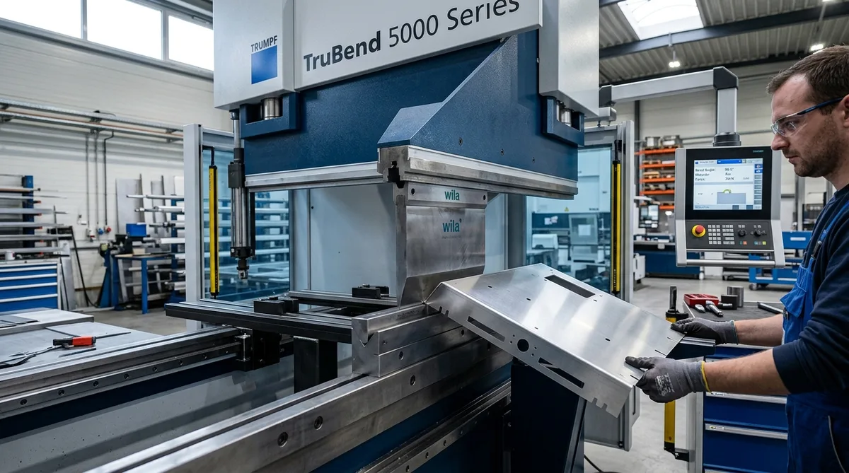
Precision sheet metal fabrication is the structural backbone of industrial equipment, telecommunication rackmounts, server enclosures, and automotive assemblies. Offering an exceptional strength-to-weight ratio, rapid production scalability, and economical material utilization, sheet metal components transition seamlessly from low-volume prototypes to high-speed mass production.
However, successful sheet metal fabrication depends on reconciling the flat 2D blank geometry with 3D formed realities. During mechanical press brake bending, metal stretches along the outer radius while compressing along the inner face, shifting the neutral axis and expanding dimensions. Without disciplined Design for Manufacturability (DFM)—including accurate K-factor calculations, hole-to-bend reliefs, and flange clearance rules—parts suffer from tear fractures, hole ovalization, and assembly misalignment. At AS Prototypes, our in-house sheet metal fabrication facility integrates high-speed fiber laser cutting, multi-axis CNC press brakes, and automated hardware insertion. Below is an engineering guide to optimizing sheet metal design, bend mechanics, and manufacturing throughput.
1. Advanced Cutting Technologies: Fiber Laser vs CNC Turret Punching
The initial flat pattern blanking process establishes edge precision, hole location accuracy, and downstream bending repeatability:
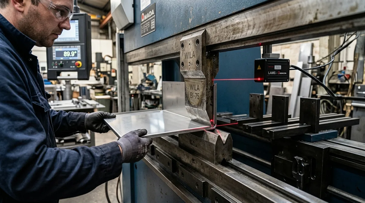
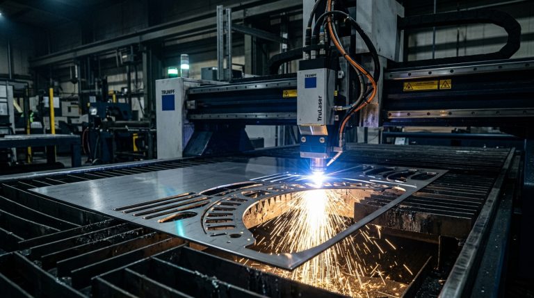
- High-Power Fiber Laser Cutting: Operating with 4kW to 12kW fiber optic lasers, our cutting systems achieve cutting kerf widths as narrow as 0.15 mm with positional repeatability within ±0.05 mm. Utilizing high-pressure nitrogen assist gas (20–25 bar) prevents edge oxidation on stainless steel and aluminum, delivering clean, dross-free edges ready for immediate welding or powder coating without secondary deburring.
- CNC Turret Punching: Highly cost-effective for high-volume perforated panels, repetitive hole grids, and specialized 3D sheet forms—such as louvers for thermal ventilation, countersinks, embosses, and card guides—formed directly on the machine table.
- Automated Dynamic Nesting: Utilizing CAD/CAM algorithmic nesting maximizes sheet yield above 85%, reducing raw material scrap and lowering overall unit costs for production runs.
2. Bending Mechanics: K-Factor, Bend Allowance, and Flat Blank Expansion
When a flat metal sheet is bent over a press brake die, plastic deformation occurs. The outer fibers undergo tensile elongation, while the inner fibers experience compressive stress. Between these two zones lies the neutral axis—a theoretical plane where material undergoes zero change in length. During bending, this neutral axis shifts inward toward the compressive surface.
The K-factor is the mathematical ratio of the neutral axis depth (t) to the total material thickness (T): K = t / T. Accurately modeling this factor is essential for calculating the correct flat blank length via Bend Allowance (BA):
BA = π · (R + K · T) · (θ / 180)
Where R is the inside bend radius, T is the sheet thickness, and θ is the bend angle in degrees. Selecting the wrong K-factor results in cumulative dimensional error across multiple flanges, causing fastener holes and chassis seams to drift out of alignment during final assembly.
3. Five Critical DFM Rules for Sheet Metal Design
Rule 1: Adhere to Minimum Bend Radius (Prevent Outer Fiber Tearing)
Specifying a sharp inside bend radius (R < 0.5t) forces the outer metal fibers beyond their ultimate tensile elongation, causing micro-fracturing or complete corner splitting. For ductile alloys like Aluminum 5052-H32 or mild steel, maintain an inside bend radius at least equal to sheet thickness (R ≥ 1.0t). For less ductile, heat-treated alloys such as Aluminum 6061-T6 or hardened stainless steel, specify R ≥ 1.5t to 2.0t.
Rule 2: Integrate Bend Relief Notches at Flange Corners
When a flange is bent without extending across the entire width of the part, the transition zone between the bent flange and adjacent flat material experiences intense tearing shear. Incorporating rectangular or tear-drop bend relief notches prevents tearing and unsightly bulging. Standard DFM rules require the relief notch depth to be greater than or equal to the inside radius plus material thickness (Depth ≥ R + T), and the notch width to be at least equal to material thickness (Width ≥ T, minimum 1.5 mm).
Rule 3: Maintain Proper Hole-to-Bend Line Spacing
Holes placed too close to a bend line sit within the plastic deformation zone. As the punch drives the sheet into the V-die, the hole expands into an irregular oval, preventing hardware installation. Maintain a minimum distance from the hole edge to the bend tangent line of 2.5 times sheet thickness plus bend radius: Distance ≥ 2.5T + R.
Rule 4: Ensure Minimum Flange Length for Die Stability
During air bending on a press brake, the sheet metal blank must span across the shoulders of the bottom V-die. If a flange is designed too short, it slips down into the V-groove before the punch completes the stroke, causing inaccurate bend angles and severe tool marks. Ensure minimum flange height meets: Flange Height ≥ 4 · T + R.
Rule 5: Account for Rolling Grain Direction
Cold-rolled sheet metal exhibits longitudinal grain structure along the rolling direction. Bending parallel to the rolling grain drastically increases the risk of tensile cracking on the outer radius. Wherever possible, nest flat patterns so that bend lines run perpendicular (90°) or diagonally (45°) to the sheet grain direction.
| Sheet Metal Alloy | Temper / Condition | Tensile Strength (MPa) | Yield Strength (MPa) | Recommended Min. Bend Radius (R/T) | Standard K-Factor |
|---|---|---|---|---|---|
| Aluminum 5052 | H32 (Strain hardened) | 210 – 260 | 130 – 180 | 1.0 · T | 0.38 – 0.42 |
| Aluminum 6061 | T6 (Solution + aged) | 290 – 310 | 240 – 275 | 1.5 – 2.0 · T | 0.40 – 0.45 |
| Stainless Steel 304 | 2B Finish (Annealed) | 515 – 620 | 205 – 240 | 1.0 · T | 0.42 – 0.46 |
| Stainless Steel 316L | Annealed | 485 – 580 | 170 – 220 | 1.0 · T | 0.42 – 0.46 |
| Mild Steel (SPCC / 1018) | Cold Rolled | 270 – 410 | 175 – 240 | 0.8 – 1.0 · T | 0.35 – 0.40 |
| Galvanized Steel (SECC) | Electro-Galvanized | 270 – 380 | 140 – 220 | 1.0 · T | 0.38 – 0.42 |
4. Hardware Insertion & Surface Finishing
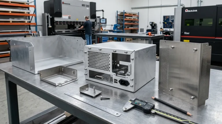
To produce fully integrated electronic chassis and mechanical enclosures, sheet metal fabrication incorporates automated secondary assembly and finishing:
- Self-Clinching PEM Fasteners: Hydraulic insertion presses install threaded nuts, studs, and standoffs into pre-lasered holes with precise squeeze force, eliminating weak tapped sheet threads and avoiding welding burn marks.
- Precision Joining: TIG, MIG, and high-speed robotic fiber laser welding create rigid, watertight seams. Robotic laser welding minimizes the Heat Affected Zone (HAZ), preventing thermal sheet warping on thin cosmetic skins.
- Protective Surface Finishes: Components receive full industrial surface finishing treatments, including chemical chromate conversion (SurTec 650), Type II/III anodizing for aluminum, and durable electrostatic powder coating (RAL color-matched) for scratch and corrosion protection.
| DFM Feature | Minimum Engineering Rule | Functional Rationale |
|---|---|---|
| Hole to Bend Distance | ≥ 2.5 · T + R | Prevents hole elongation and oval distortion in the bend deformation zone |
| Bend Relief Width | ≥ T (minimum 1.5 mm) | Allows laser cutting kerf clearance and prevents adjacent metal tearing |
| Bend Relief Depth | ≥ R + T | Ensures full relief beyond the theoretical bend tangent line |
| Minimum Flange Length | ≥ 4 · T + R | Provides stable purchase across lower press brake V-die shoulders |
| Hole to Edge Distance | ≥ 2.0 · T | Prevents edge bulging and material tear-out during blanking and punching |
Frequently Asked Questions
The K-factor is the ratio of neutral axis position to sheet metal thickness during bending. Because the metal stretches on the outside and compresses on the inside, the neutral axis shifts inward. An accurate K-factor is required to calculate the exact flat blank cutout length before bending, preventing cumulative dimensional errors in multi-flange assemblies.
Holes placed within the plastic deformation zone of a bend line stretch into an egg or oval shape as the metal is drawn into the press brake die. To prevent distortion, keep the distance from the edge of any cutout or hole to the bend line at least 2.5 times material thickness plus the inside bend radius (Distance >= 2.5T + R).
In sheet metal thinner than 2.5 mm, directly tapped threads offer insufficient thread engagement (fewer than 3 full threads), making them prone to stripping under torque. Self-clinching PEM nuts and standoffs cold-flow into pre-cut holes, providing high pull-out and torque-out resistance without damaging protective finishes.
Streamline Your Sheet Metal Fabrication
From rapid prototype brackets to complex multi-part welded electronic chassis, AS Prototypes provides high-precision CNC fiber laser cutting, press brake bending, hardware insertion, and powder coating. Upload your STEP or DXF files today for an instant DFM review and quote.