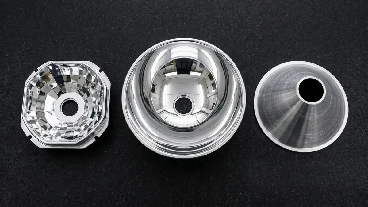
In modern illumination engineering, commercial stadium lighting, automotive exterior forward lighting, and concentrated solar optics, the reflector is the primary engine of optical transmission. It is tasked with capturing non-directional luminous flux from high-power LEDs or arc sources and redirecting that energy into precise target beam patterns with minimal parasitic absorption.
Aluminum stands as the undisputed substrate of choice, offering intrinsic optical reflectivity exceeding 90% across the visible spectrum (380 to 780 nm), exceptional thermal conductivity (130 to 200 W/(m·K)) to conduct away high thermal flux, and low specific gravity.
However, executing aluminum reflector prototyping requires navigating precision manufacturing technologies—spanning Single-Point Diamond Turning (SPDT), CNC metal spinning, and CNC micro-milling (3-axis and 4-axis, with 5-axis for faceted freeform masters)—paired with chemical bright-dip etching and optical-grade thin anodizing to achieve mirror specular reflection without orange-peel haze. For luminaires and automotive housings that pair these reflectors with LED modules, our lighting optics and housing prototyping team reviews CAD for thermal and optical co-design before any metal is cut.
- 1. Optical Physics & Reflector Geometry Fundamentals
- 2. Optical Aluminum Metallurgy & Alloy Selection Matrix
- 3. Single-Point Diamond Turning (SPDT) vs CNC Metal Spinning
- 4. Optical Micro-Roughness & The Davies-Bennett Scattering Relation
- 5. Surface Finishing, Bright-Dip & Thin-Film Dielectric Anodizing
- 6. Thermal Dissipation & LED Module Co-Design
- 7. Metrology, Precision Surface Profilometry & Photometric Verification
- 8. Failure Analysis & Workshop Troubleshooting Matrix
- 9. Technical Engineering FAQ
1. Optical Physics & Reflector Geometry Fundamentals
The design of an optical reflector operates strictly on the fundamental Law of Reflection, which dictates that the angle of incidence (θi) equals the angle of reflection (θr) relative to the surface normal vector. In real-world manufactured reflectors, reflected light is categorized into two regimes:
- Specular (Mirror) Reflection: Light rays maintain an identical parallel relationship upon reflection, producing sharp, high-intensity beam concentration without luminous dispersion. Specular reflection requires the root-mean-square (RMS) surface roughness of the metal substrate to be significantly smaller than the wavelength of the incident light (σ ≪ λ).
- Diffuse (Lambertian) Scattering: Microscopic surface irregularities scatter incoming rays at random angles according to Lambert’s cosine law, turning directed light into wasted stray glare, reducing peak center-beam candlepower (CBCP), and creating a milky cosmetic haze.
Mathematical Foundations of Primary Optical Curvatures
To produce specific photometric distributions, optical engineers employ rigorous mathematical curves:
- Parabolic Reflectors (Collimation): A parabola represents the locus of points equidistant from a focal point F and a directrix line. When an LED emitter is placed precisely at the focal point (0, 0, f), all light rays striking the parabolic surface reflect perfectly parallel to the central optical axis (Z-axis). The rotational profile is governed by the classic quadratic equation:
z = r² / (4 · f) = (x² + y²) / (4 · f)
where f is the focal length and r is the radial distance from the optical axis. Parabolic reflectors are universally deployed in searchlights, long-range automotive high beams, and surgical downlights where maximum center-beam throw distance is the priority. - Elliptical Reflectors (Focal Coupling): Ellipsoidal profiles possess two conjugate focal points (F1 and F2). Light originating from an emitter at F1 naturally converges at secondary focus F2. This geometry is essential in automotive projector headlamps, fiber optic illuminators, and light guide entry ports where luminous energy must be funneled through a compact aperture or cut-off shutter plate.
- Multifaceted & Freeform Segmented Reflectors: While continuous rotationally symmetric curves provide high peak intensity, they frequently project imaging artifacts from the LED die (such as dark yellow rings or square emitter shadows). Multifaceted reflectors segment the curvature into tens or hundreds of mathematically calculated planar or toroidal micro-facets. Each individual facet superimposes an overlapping beam image onto the target field, blending color-over-angle (CoA) variations and delivering a homogenous, streak-free illumination field.
2. Optical Aluminum Metallurgy & Alloy Selection Matrix
Unlike standard mechanical CNC machining where yield strength and elongation dictate material choice, optical reflector fabrication is dominated by micro-structural purity. The presence of hard intermetallic secondary phases, iron-rich precipitates, and insoluble silicon inclusions will tear through the cutting edge during diamond turning, causing micro-voids, pitting, and optical clouding.
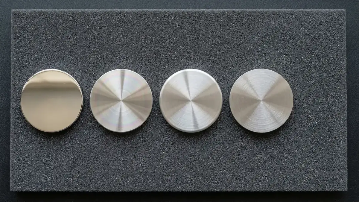
1. High-Purity Aluminum (Al 99.85% / Alloy 1070 / 1085)
Commercially pure aluminum grades with minimal iron (Fe < 0.08%) and silicon (Si < 0.06%) represent the global benchmark for high-specularity optics. In standard aluminum alloys, insoluble iron aluminide particles (FeAl3) act as localized cathodes during chemical etching, producing micro-galvanic pitting that destroys specular gloss. High-purity Al 1085 eliminates these micro-inclusions entirely.
When subjected to chemical bright-dipping, it develops an extraordinarily deep, distortion-free specular shine with total reflectance exceeding 92%. In the fully annealed O-temper, Al 1085 exhibits extreme ductility (elongation > 35%), making it the premier choice for CNC metal spinning and deep drawing of parabolic cups.
2. Optical-Grade RSA-6061 & Fine-Grain 6061-T6
When reflectors require complex structural features—such as integrated heat sink cooling fins, threaded alignment bosses, or thin multifaceted walls—pure aluminum lacks sufficient mechanical rigidity. Standard commercial 6061-T6 contains coarse Mg2Si precipitates and iron-manganese intermetallics that cause tool chatter and micro-tearing during diamond turning.
AS Prototypes resolves this by selecting Rapid Solidification Aluminum (RSA-6061) or fine-grain, vacuum-remelted 6061-T6 billets. RSA technology rapidly quenches the molten alloy at >1,000,000 °C/s, freezing micro-constituents into sub-micron precipitates. This ultra-refined grain structure enables Single-Point Diamond Turning directly to an optical mirror finish with roughness Ra ≤ 0.003 μm (3 nm) without pull-out defects.
3. Al 5052-H32 & Al 3003 Alloys
Magnesium-alloyed 5052-H32 provides higher tensile yield strength (193 MPa vs 75 MPa for pure Al) and superior fatigue resistance in environments subject to severe mechanical vibration, such as commercial truck headlamps and marine luminaires. While its magnesium content slightly lowers total specular reflectance to 86–89% after anodizing, it remains the standard choice for medium-duty spun industrial reflector hoods and outdoor architectural floodlights.
| Alloy Grade | Purity / Key Chemistry | Delivery Temper | Yield Strength (MPa) | Max Specular Reflectance | Achievable Roughness (Ra) | Primary Manufacturing Method | Target Illumination Application |
|---|---|---|---|---|---|---|---|
| Al 1085 / 1070 | 99.85% Pure Al (Fe < 0.08%, Si < 0.06%) | O (Annealed) / H14 | 35 – 85 MPa | 92% – 94% | ≤ 0.015 μm (Bright dip) | CNC Metal Spinning, Deep Drawing | Architectural downlights, stage lights, high-bay commercial luminaires |
| RSA-6061 | Rapid Solidification Al-Mg-Si | T6 (Solution & Aged) | 276 MPa | 90% – 93% | ≤ 0.003 μm (3 nm SPDT) | Single-Point Diamond Turning (SPDT) | Automotive LED headlamp optics, laser collimators, aerospace searchlights |
| Fine-Grain 6061-T6 | Vacuum Remelted Al-Mg-Si | T651 Billet | 276 MPa | 88% – 91% | 0.005 – 0.010 μm | High-Speed 3-Axis & 4-Axis CNC Milling (5-Axis for Faceted Masters), SPDT | Faceted complex reflectors, structural reflector bodies with integral heat sink |
| Al 5052-H32 | Al-2.5% Mg-0.25% Cr | H32 (Strain Hardened) | 193 MPa | 86% – 89% | 0.020 – 0.040 μm | CNC Metal Spinning, Stamping | Marine floodlights, industrial mining luminaires, high-vibration truck lamps |
3. Single-Point Diamond Turning (SPDT) vs CNC Metal Spinning
Selecting the optimal manufacturing methodology balances geometric complexity, optical surface tolerance, and rapid prototyping economics:
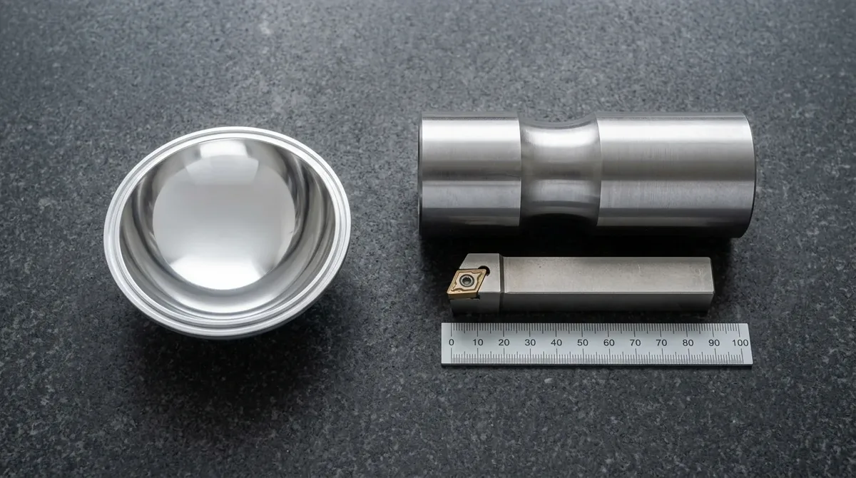
Process 1: Single-Point Diamond Turning (SPDT)
SPDT is the apex manufacturing technology for producing ultra-precision aspheric, off-axis parabolic, and continuous freeform optical reflectors directly in aluminum billet. SPDT lathes operate in temperature-controlled (20 °C ± 1 °C) environments on natural granite vibration-isolated beds. Key architectural characteristics include:
- Porous Aerostatic Spindles: Air-bearing spindles deliver radial and axial runout below 15 nm across rotational speeds from 500 to 6,000 RPM.
- Hydrostatic or Air-Bearing Linear Slideways: Driven by linear ironless brushless motors with high-resolution optical encoder feedback for smooth contour interpolation.
- Monocrystalline Diamond (MCD) Cutters: Gem-quality natural or synthetic monocrystalline diamond tools with an atomically sharp cutting edge radius (Redge < 20 nm) and flawless zero-defect cutting edge waviness.
In SPDT, the theoretical peak-to-valley surface roughness (Rth) is mathematically dictated by tool nose radius (Rnose) and the feed rate per revolution (ffeed):
Rth ≈ ffeed² / (8 · Rnose)
The arithmetic average roughness (Ra) for an ideal circular cutting tool path is calculated as:
Ra ≈ ffeed² / (18 · √3 · Rnose) ≈ 0.032 · [ ffeed² / Rnose ]
By feeding a 1.0 mm nose radius diamond tool at an ultra-fine feed of 1.5 μm per revolution (ffeed = 0.0015 mm/rev), the theoretical surface roughness is a staggering Ra = 0.07 nm! In shop practice, material micro-plasticity and minimal spindle micro-vibrations yield real-world roughness of Ra = 1.5 to 3.0 nm directly from the toolpath, delivering an optically flawless mirror finish requiring zero post-machining polishing.
Process 2: CNC Metal Spinning
For rotationally symmetric deep parabolic bowls, high-bay cones, and architectural downlight reflectors, CNC metal spinning represents the most economical rapid prototyping and bridge manufacturing method. A pre-cut circular aluminum sheet blank (typically 1.0 to 1.5 mm thick Al 1085-O) is clamped against a precision CNC machined steel or hard aluminum mandrel tool. As the lathe spins at 1,200 to 2,500 RPM, CNC hydraulic servo-controlled forming rollers apply localized pressure in progressive back-and-forth passes, plasticizing the metal and flowing it tightly over the mandrel contour.
Key advantages of CNC spinning for prototyping include:
- Low Tooling Investment: Spinning requires only a single male mandrel tool (unlike costly male/female stamping dies), reducing tooling costs by over 80%. Mandrels are CNC turned from 45# carbon steel or 7075 aluminum within the same 7 to 12 business day prototype window.
- Rapid Iterative Agility: Prototype reflectors can be formed, chemically brightened, and shipped within 7 to 12 business days. Optical beam angle adjustments only require a fast re-cut of the mandrel diameter or focal curvature.
- Uniform Wall Thickness: Multi-axis CNC spinning programs control material shear and thinning, ensuring uniform 0.8 to 1.2 mm wall thickness throughout the cup without localized necking or tearing.
4. Optical Micro-Roughness & The Davies-Bennett Scattering Relation
Why is nanometer-scale surface roughness so critical for an aluminum reflector? The answer lies in the physics of electromagnetic wave scattering from micro-rough conductive surfaces. In 1961, H. Davies and H.E. Bennett established the theoretical relationship governing how surface micro-roughness degrades specular reflection into diffuse scatter.
The specular reflectance (Rs) of a smooth metal surface at normal incidence diminishes exponentially as a function of the root-mean-square (RMS) surface roughness (σ = Rq) relative to the light wavelength (λ):
Rs = R0 · exp[ – ( (4 · π · σ · cos θi) / λ )² ]
where:
- R0: The theoretical specular reflectance of an atomically smooth aluminum surface calculated from Fresnel reflection equations (approximately 92.5% for bare aluminum at λ = 550 nm).
- σ: The RMS surface roughness of the reflector substrate (nm).
- θi: The angle of incidence relative to the surface normal.
- λ: The optical wavelength of the incident light (nm). In the visible spectrum, green light (λ = 550 nm) represents the photopic peak of human ocular sensitivity.
The fraction of incident luminous energy lost to diffuse scatter—known as Total Integrated Scatter (TIS)—is derived from conservation of energy:
TIS = 1 – (Rs / R0) ≈ [ (4 · π · σ · cos θi) / λ ]²
Consider the quantitative implications: For an aluminum surface with an ordinary fine CNC milled roughness of Ra = 0.20 μm (200 nm, σ ≈ 250 nm), the exponent evaluates to a massive value, reducing specular reflectance Rs virtually to 0%! All reflected light becomes diffuse white scatter. To achieve greater than 98% of maximum specular efficiency (TIS ≤ 2%), the RMS micro-roughness σ must be strictly controlled to:
Optical Threshold: σ ≤ λ / (4 · π · √50) ≈ 550 nm / (4 · 3.1416 · 7.07) ≈ 6.2 nm (Ra ≤ 4.8 nm)
This mathematical proof underlines why standard mechanical machining can never produce functional optics, and why AS Prototypes enforces single-point diamond turning and chemical bright-dip polishing down to Ra ≤ 3 nm.
5. Surface Finishing, Bright-Dip & Thin-Film Dielectric Anodizing
Freshly cut aluminum possesses high native reflectivity, but when exposed to atmospheric air, it spontaneously forms a thin, amorphous, porous oxide film that attracts moisture, oils, and airborne sulfides, causing specular reflectivity to degrade within weeks. However, conventional architectural anodizing (15 to 25 μm coating thickness) is disastrous for optics; its deep cellular hexagonal pores scatter light violently, creating a milky, cloudy haze that drops reflectance to 65–75%.
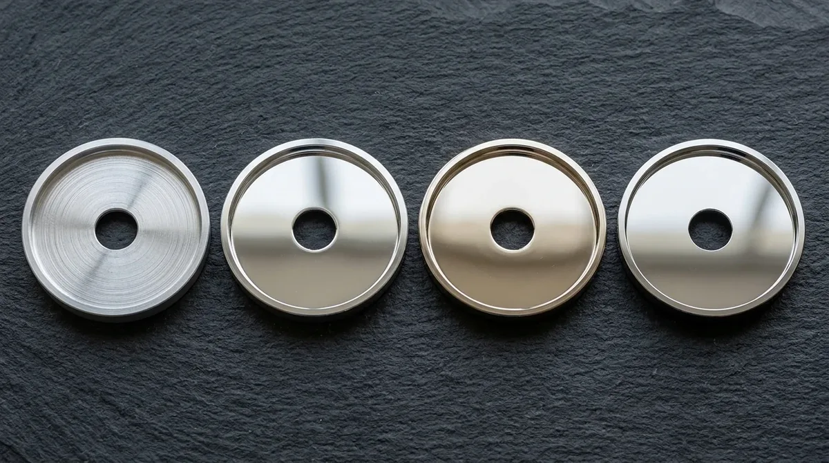
The 3-Step Optical Finishing Regime at AS Prototypes
- Chemical Brightening (Bright-Dip): Submerging the formed aluminum reflectors in an engineered hot acidic electrolyte (typically 80–85% concentrated phosphoric acid H3PO4, 3–5% nitric acid HNO3, balanced with trace copper sulfate catalysts) maintained at 95 °C to 105 °C for 60 to 180 seconds. The bath establishes a dynamic diffusion layer where microscopic surface asperities dissolve at a rate dramatically faster than valleys. This micro-leveling process eradicates sub-micron toolmarks, yielding a brilliant mirror specular luster with zero orange peel.
- Ultra-Thin Optical Clear Anodizing (3 to 5 μm): Following bright-dipping, the reflectors are immediately transferred to an chilled sulfuric acid anodizing bath (15% H2SO4 at 18 °C to 20 °C) operated at a precisely controlled current density of 1.0 to 1.2 A/dm². Rather than growing a thick 15–25 μm architectural layer, the process is timed strictly to build an ultra-thin 3.0 to 5.0 μm optical barrier layer. The pore structure is then completely sealed in deionized water at >98 °C with chemical anti-smut agents. This preserves ≥92% specular reflectance while providing surface hardness (HV > 350) and corrosion resistance exceeding 240 hours of ASTM B117 neutral salt spray testing.
- Vacuum PVD Enhanced Dielectric Metallization: For demanding laser, astronomical, and medical projection applications requiring maximum possible throughput, diamond-turned aluminum reflectors undergo Physical Vapor Deposition (PVD). Under high vacuum (10-5 mbar), an ultra-pure aluminum film (99.999% Al) is thermally evaporated or magnetron sputtered onto the surface, followed by dual dielectric interference layers of silicon dioxide (SiO2) and titanium dioxide (TiO2). The dielectric layers create constructive optical interference that elevates total specular reflectance to an incredible 95% to 97% across the visible spectrum.
| Finishing Treatment Regime | Layer Thickness | Total Specular Reflectance | Diffuse Scatter (TIS) | Salt Spray Durability (ASTM B117) | Max Operating Temp (°C) | Target Optical Application |
|---|---|---|---|---|---|---|
| Bare SPDT Diamond Turned Al | None (Native oxide ∼3 nm) | 88% – 91% | < 1.5% | Poor (< 24h) | 150 °C | Hermetically sealed optical modules, laboratory laser sensors |
| Bright Dip + Thin Clear Anodize | 3.0 – 5.0 μm Al2O3 | 91% – 94% | 1.5% – 3.0% | > 240 hours (Excellent) | 200 °C | Commercial downlights, stadium luminaires, automotive lamps |
| Vacuum PVD Enhanced (Al + SiO2) | ∼150 nm Al + ∼120 nm SiO2 | 95% – 97% | < 0.8% | Moderate (> 96h) | 120 °C | Astronomical searchlights, laser collimators, medical projectors |
| Architectural Anodizing (Standard) | 15 – 25 μm Al2O3 | 65% – 75% (Cloudy) | 25% – 35% (Severe haze) | > 1,000 hours | 250 °C | Non-optical external bezels, heat sink housings (Unsuitable for optics) |
6. Thermal Dissipation & LED Module Co-Design
Modern Chip-on-Board (COB) LEDs and high-intensity automotive laser diode packages generate immense localized heat flux, dissipating between 50W and 300W of thermal energy across footprints smaller than a postage stamp. High junction temperatures (>105 °C) degrade LED lumen output, accelerate phosphor degradation, and cause irreversible chromaticity color shift. Aluminum reflectors provide an engineered dual advantage: they function simultaneously as the primary optical collimator and as a primary or secondary thermal heat spreader.
Thermal Expansion & Focal Stability
Because aluminum has a relatively high coefficient of thermal expansion (α = 23 × 10-6 K-1), thermal cycling from ambient (20 °C) up to steady-state operational temperature (85 °C to 110 °C) causes physical dimensional growth:
ΔL = L0 · α · ΔT
For a 120 mm (4.72″) diameter parabolic reflector (radius R0 = 60 mm) with an operating temperature rise of ΔT = 70 °C, the diametral expansion is ΔD = 0.193 mm (radial expansion ΔR = 0.097 mm), and the focal position shifts along the Z-axis by ∼0.05 mm.
While negligible in broad floodlights, this thermal shift will defocus narrow-beam automotive spotlights (beam angle < 8°), degrading peak candela. AS Prototypes collaborates with client optical teams during DFM review to incorporate kinematic flexure mounting tabs and thermally isolated alignment pins that accommodate thermal expansion symmetrically around the optical center without introducing beam distortion. When a polymer reflector with a vapor-deposited aluminum film fits the packaging better than a machined metal bowl, compare substrates in our guide to automotive headlamp prototype materials.
7. Metrology, Precision Surface Profilometry & Photometric Verification
Optical reflector prototypes manufactured at AS Prototypes are verified in our 20 °C ± 1 °C climate-controlled metrology lab through contact, non-contact optical, and photometric inspection protocols:
1. Precision Surface Profilometry & Optical Gloss Metrology
Pre-finish machined reference flats and sacrificial witness coupons are verified using a calibrated Contact Stylus Profilometer (per ISO 4287 / ASME B46.1) to confirm baseline roughness (Ra, Rz) without scratching the active optical aperture. For the finished reflector bowl, non-contact 2.5D Optical Vision Measuring Systems (VMS) and multi-angle specular glossmeters (ASTM D523 at 20°, 60°, and 85° incident geometries) verify surface specularity and micro-facet alignment.
2. Optical Form Coordinate Metrology (CMM Datum A)
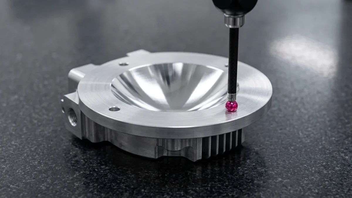
Geometric contour profile accuracy and mounting interfaces are verified on our Zeiss Bridge CMM (available upon request for critical dimensional inspection) paired with calibrated Go/No-Go pin and thread gauges. By establishing master Datum A on the precision-machined rear mounting flange and Datum B/C on dowel pin bores, we verify the 3D profile and mounting features against the master CAD model, holding critical datum tolerances within ±0.010 mm (±0.0004 in).
3. Spectrophotometer & Goniophotometer Photometric Verification
- Spectrophotometer Reflectance Curve: Utilizing a dual-beam UV-Vis-NIR spectrophotometer fitted with an integrating sphere, we measure total hemispherical reflectance and specular vs. diffuse scatter across wavelengths from 380 nm to 780 nm according to ASTM E903 standards.
- Goniophotometer IES Testing: In our optical darkroom, the reflector prototype is mated with the client’s specified LED module inside a Type-C distributed goniophotometer. We capture complete 3D luminous intensity distribution data (polar candela curves), beam cutoff angles, total optical efficiency (%), and generate industry-standard IES / LDT photometric data files for direct import into DIALux and Relux lighting simulation software.
8. Failure Analysis & Workshop Troubleshooting Matrix
The manufacturing of precision aluminum reflectors involves complex metallurgical and electrochemical interactions. The following matrix illustrates AS Prototypes’ failure analysis protocol and shop floor countermeasures:
| Optical Defect | Visual / Photometric Symptom | Root Cause Mechanism | Shop-Floor Tooling Countermeasure |
|---|---|---|---|
| Orange Peel Texture | Waviness and mottled diffuse reflection visible under inspection lamp | Excessive grain size in raw aluminum sheet; severe over-stretching during metal spinning | Switch to fine-grain recrystallized Al 1085 sheet; increase number of spinning roller passes to reduce localized strain rate |
| Diamond Turning Chatter | Periodic radial bands or wave ripples along cutting spiral; increased TIS scatter | Micro-vibration harmonics; vacuum chuck clamping distortion; inadequate air spindle pressure | Optimize vacuum fixture nest to support thin outer flange; tune spindle rotational speed away from resonant frequency; reduce depth of cut to ≤ 1.5 μm |
| Diffraction Rainbow Glare | Prismatic color separation bands visible on illuminated target field | Periodic diamond toolpath pitch acts as a microscopic optical diffraction grating | Apply random micro-dithering to feed rate in CNC toolpath; perform light sub-micron chemical brightening to soften periodic tool cusps |
| Micro-Pitting After Bright-Dip | Microscopic dark pinholes visible under optical microscope | Insoluble iron/silicon inclusions in lower-grade aluminum causing micro-galvanic corrosion in acid | Mandate ≥99.85% high-purity aluminum with Fe < 0.08%; adjust phosphoric-nitric acid ratio and bath temperature (98 °C) |
| Cloudy / Milky Anodize | Reflectance drops from 93% to <80%; white veil covers mirror surface | Anodizing layer exceeded 5 μm; bath temperature too high (>22 °C); contaminated sealing water | Limit anodizing duration to 3–4 minutes (thickness strictly 3.0–4.0 μm); chill bath to 18 °C; use deionized water (conductivity < 5 μS/cm) |
9. Technical Engineering FAQ
High-purity aluminum (Al 1085 / 1070) contains less than 0.08% iron and 0.06% silicon, virtually eliminating insoluble intermetallic secondary phases. When subjected to chemical bright-dip polishing, it develops a deep, crystal-clear specular shine exceeding 92% reflectance with zero micro-pitting. Standard 6061 contains magnesium and silicon precipitates that cause light scattering, making it ideal for structural parts but less optimal for pure specular spun bowls.
According to the Davies-Bennett electromagnetic scattering relation, surface micro-roughness must remain substantially below the incident light wavelength to prevent diffuse scatter. In the visible spectrum (550 nm), maintaining over 98% specular reflection efficiency requires an arithmetic average surface roughness of Ra ≤ 3 nm (0.003 μm), which AS Prototypes achieves through Single-Point Diamond Turning (SPDT) and specialized optical bright-dipping.
Standard architectural anodizing deposits a thick (15 to 25 μm) porous oxide layer that causes violent Rayleigh light scattering, dropping specular reflectivity down to 65–75%. Optical finishing employs chemical bright-dip micro-leveling followed by an ultra-thin (3.0 to 5.0 μm), highly transparent clear anodized barrier that preserves ≥92% specular reflectance while providing over 240 hours of ASTM B117 salt spray protection.
Factory production turnaround for functional CNC spun aluminum reflector prototypes strictly ranges from 7 to 12 business days, including mandrel tooling fabrication, metal spinning, and bright-dip anodizing. Complex single-point diamond turned (SPDT) freeform reflectors or multifaceted milled masters (5-axis only where facet angles require it) with CMM inspection turn around within 7 to 12 business days as well, quoted per CAD after DFM review. All lead times are Ex-Factory Production & Inspection Turnaround, separate from 3 to 5 days DHL/FedEx air transit.
Yes. Utilizing high-speed 3-axis and 4-axis CNC milling (5-axis for steep faceted contours), micro-step milling toolpaths, diamond flycutting, and multi-axis SPDT lathes, AS Prototypes manufactures complex faceted and freeform aluminum reflectors tailored to custom photometric beam patterns for automotive headlamps, architectural floodlights, and laser projection systems.
Partner with Our Optical CNC Machining, SPDT & Finishing Team
Achieve mirror-grade Ra ≤ 3 nm specular finishes, tight parabolic contour tolerances, and optical bright-dip anodizing compliance from billet diamond turning through CNC metal spinning. Upload your 3D CAD models (STEP/IGES) and optical drawings for a complete DFM review.
Upload 3D CAD for Optical & Finishing DFM Review