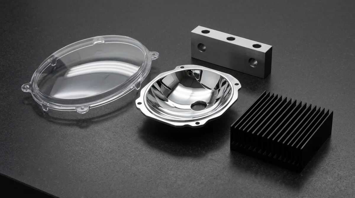
Automotive headlamp prototype materials determine whether a lighting model survives thermal soak, stone-chip testing, and photometric measurement before steel tooling is cut. Optical-grade polycarbonate (PC) lenses, polymethyl methacrylate (PMMA) light guides, polyetherimide (PEI) reflector substrates, and 6061-T6 aluminum heatsinks each solve a different failure mode in one assembly. In our in-house machine shop, we match every subassembly to its optical, thermal, and mechanical duty.
⏱️ Estimated Reading Time: ~9 mins | Target Audience: Mechanical Design Engineers, R&D PMs, Sourcing Specialists
Written by: AS Prototypes Precision Engineering Team | Technically Reviewed by: Tooling & Optical Machining Specialist (12+ Years Shop-Floor Experience)
- Lens materials: optical PC for impact toughness; PMMA for 91 ~ 93% light transmission.
- Reflector stack: PEI or PBT-GF20 substrate, UV basecoat, PVD aluminum 80 ~ 150 nm, SiOx topcoat.
- Precision: SPDT optics to Ra ≤ 10 nm (0.4 µin); housing fits at ±0.010 ~ ±0.020 mm (±0.0004 ~ ±0.0008″).
- Lead time: 7 ~ 12 Business Days Ex-Factory Production & Inspection Turnaround for finished optical sets, separate from 3 ~ 5 Days DHL/FedEx air transit; quote and DFM feedback Within 24 Hours.
Why Choose Polycarbonate Over PMMA for Automotive Headlamp Lenses?
Optical polycarbonate (PC) is selected for outer headlamp lenses because a notched Izod impact of 640 ~ 850 J/m (12 ~ 16 ft·lbf/in) survives stone chipping, while PMMA transmits more light (91 ~ 93%) but fractures at 16 ~ 27 J/m (0.3 ~ 0.5 ft·lbf/in). Thermal margin then decides the stack: PC holds shape near 130 °C (266 °F), whereas PMMA softens near 95 ~ 105 °C (203 ~ 221 °F).
Solar yellowing is the failure that bare PC cannot avoid. Prototype PC lenses therefore receive a UV-curable polysiloxane hard coat of 5 ~ 10 µm (0.0002 ~ 0.0004″), which suppresses yellowing and abrasion haze during accelerated weathering. PMMA keeps its clarity without a coat, but its low impact resistance demands rib support behind the lens.
| Property | Optical PC | Optical PMMA | Recommended Application / When to Choose |
|---|---|---|---|
| Refractive Index (nd) | 1.586 | 1.491 | Choose PC for shorter focal lengths and thinner projector lenses |
| Light Transmission (%) | 88 ~ 90 | 91 ~ 93 | Choose PMMA for DRL light guides where luminous efficiency dominates |
| Abbe Number (Vd) | ≈ 30 | ≈ 57 | Choose PMMA when chromatic fringing at the cut-off line is critical |
| HDT at 1.8 MPa (°C / °F) | 128 ~ 138 (262 ~ 280 °F) | 92 ~ 105 (198 ~ 221 °F) | Choose PC beside high-output LED arrays and projector modules |
| Notched Izod Impact (J/m) | 640 ~ 850 (12 ~ 16 ft·lbf/in) | 16 ~ 27 (0.3 ~ 0.5 ft·lbf/in) | Choose PC for exposed outer lenses facing stone chips |
| CTE (10⁻⁶ / K) | 65 ~ 70 | 70 ~ 77 | Slot every mounting hole for either polymer (see thermal section) |
When to avoid: skip PMMA for exposed outer lenses in any program that requires stone-chip validation, and keep unprotected PC away from adhesives or cleaners containing esters or ketones, which trigger environmental stress cracking around screw bosses. Neither polymer replaces glass where continuous exposure above 130 °C (266 °F) is expected.
Precision Optical Machining: Single-Point Diamond Turning and Micro-Milling
Single-point diamond turning (SPDT) is an ultra-precision machining process in which a monocrystalline diamond tool on an air-bearing spindle cuts PMMA, PC, or aluminum optics to form accuracy of ≤ 0.5 µm Peak-to-Valley (PV) and Ra ≤ 10 nm (0.4 µin). Aspheric projector lenses above 80 mm (3.15″) aperture or with steep local slopes exceed practical SPDT travel and move to micro-milling plus vapor polishing.
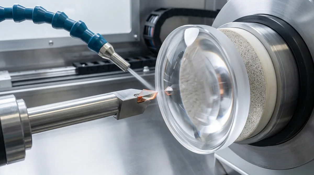
In the SPDT setup shown below, an aerostatic porous ceramic vacuum chuck holds the PMMA blank by its flat rear face, so no jaw clamping stress distorts the optical curve. A vortex cold air jet clears chips at the monocrystalline diamond tool tip, avoiding coolant that would craze acrylic.
- Step 1: Stress-Relieve the Blank – Anneal PMMA blanks at 80 °C (176 °F), then cool at ≤ 10 °C/h to remove residual stress that would otherwise appear as birefringence after cutting.
- Step 2: Rough with High-Speed Micro-Milling – Use Ø1.0 ~ 2.0 mm diamond-coated ball mills at 40,000 RPM (Vc ≈ 126 ~ 251 m/min) with fz ≈ 0.005 ~ 0.02 mm/tooth, leaving 0.05 mm (0.002″) finishing stock.
- Step 3: Finish with SPDT – Run 1,000 ~ 3,000 RPM with a 2 ~ 5 µm/rev feed and 2 ~ 5 µm depth of cut under vortex cold air to reach Ra ≤ 10 nm.
- Step 4: Vapor Polish PC Only – Expose milled PC to controlled solvent vapor, then anneal at 60 ~ 80 °C (140 ~ 176 °F) for 2 ~ 4 hours to relieve solvent stress and prevent delayed micro-crazing.
- Step 5: Inspect Without Contact – Verify form with optical profilometry or interferometry, because a touch-probe Coordinate Measuring Machine (CMM) scratches soft polymer surfaces.
In our Shenzhen machine shop practice, we reserve a fresh diamond tool edge for each PMMA finishing pass on aspheres, because edge micro-chipping first shows up as haze near the beam cut-off zone. For large freeform bezels and textured trim, High-Speed 3-Axis & 4-Axis CNC Milling with datum shift control and chatter suppression holds true position within ±0.010 mm (±0.0004″).
Headlamp Subassembly Materials and Manufacturing Methods
A prototype headlamp assembly combines five material systems: an optical PC outer lens, a PEI or PBT-GF20 reflector, a PMMA light guide, a PP-TD20 or PBT-ASA housing, and a 6061-T6 aluminum heatsink. Each subassembly pairs with a prototype process matched to its optical or thermal duty.
| Subassembly | Base Material | Prototype Process | Surface Finish / Coating | Recommended Application / When to Choose |
|---|---|---|---|---|
| Outer Lens | Optical PC | High-Speed 3-Axis & 4-Axis CNC Milling (5-Axis for Freeform Contours) + vapor polishing | Hard coat 5 ~ 10 µm; Ra ≤ 0.05 µm (2 µin) | Functional lens validation; move to rapid tooling for repeat lens runs |
| Freeform Reflector | PEI (Ultem) / PBT-GF20 | CNC micro-milling or rapid tooling | UV basecoat 10 ~ 20 µm + PVD aluminum 80 ~ 150 nm + SiOx topcoat | LED reflectors that need ≥ 88% specular reflectance |
| DRL Light Guide | Optical PMMA | SPDT + micro-milling | Ra ≤ 0.01 µm (0.4 µin) | Light pipes and collimators where total internal reflection controls efficiency |
| Rear Housing | PP-TD20 / PBT-ASA | Rapid tooling (polyurethane vacuum casting for appearance units) | VDI 3400 No. 27 texture + overmolded EPDM gasket | Sealed housings that must survive thermal cycling and vibration |
| LED Heatsink Core | 6061-T6 aluminum / ADC12 | High-Speed 3-Axis CNC Milling | Black anodizing (MIL-A-8625 Type II) | Thermal path from LED board to housing; raises emissivity |
Housings, bezels, and heatsink cores follow different rules than optics. For these lighting structural prototypes, our in-house lighting housing and optics machining holds critical locating fits at ±0.010 ~ ±0.020 mm (±0.0004 ~ ±0.0008″), while black anodizing per MIL-A-8625 Type II raises thermal emissivity on heatsink cores.
Rear housings in PP-TD20 or PBT-ASA made through rapid tooling need rib thickness of ≤ 0.6 × nominal wall to prevent sink marks. Gates sit away from the lens sealing flange so knit lines never cross the adhesive bead, and a VDI 3400 No. 27 texture requires at least 1° of added draft per side.
How Does PVD Aluminum Metallization Produce Mirror-Grade Headlamp Reflectors?
Physical vapor deposition (PVD) aluminum metallization evaporates 99.99% aluminum in a 10⁻⁴ ~ 10⁻⁵ mbar vacuum and deposits an 80 ~ 150 nm mirror film that reaches ≥ 88% specular reflectance across 400 ~ 700 nm. Substrate roughness above Ra 0.1 µm (4 µin) telegraphs through the film as haze unless a UV basecoat levels the surface first.
A plasma-polymerized siloxane (SiOx) topcoat then seals the raw aluminum against oxidation and moisture, giving thermal endurance to roughly 160 °C (320 °F) near LED emitters. We machine reflectors from PEI or PBT-GF20 because both tolerate the 120 ~ 140 °C (248 ~ 284 °F) bake of the basecoat cycle.
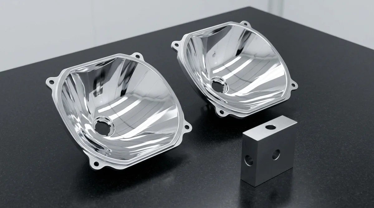
The reflector pair below shows the finished result on a flat metrology plate: both bowls rest on their rear mounting flanges, and the multi-facet parabolic cavities reflect only broad overhead strip light as clean white bands, which confirms uniform film thickness and the absence of orange-peel texture.
Troubleshooting: Iridescent Haze on Metallized Reflectors
- Symptom: Rainbow or milky haze appears on the reflector after a 85 °C (185 °F) thermal soak.
- Root Cause: Moisture or volatiles outgassing from unbaked polymer or an undercured UV basecoat condense inside the aluminum film.
- Corrective Action: Pre-bake substrates for 4 hours at 80 ~ 100 °C (176 ~ 212 °F), confirm basecoat cure dose, and re-run a thermal soak before releasing the set.
Thermal Expansion, Venting, and Fogging Control in Headlamp Prototypes
Thermal expansion mismatch between a PC lens (α ≈ 68 × 10⁻⁶ / K) and a 6061-T6 aluminum heatsink (α ≈ 23 × 10⁻⁶ / K) produces 0.35 mm of differential growth across a 120 mm (4.72″) span at an 85 °C (185 °F) soak. Rigid screw bosses without float bow the lens and shift the beam pattern.
The calculation follows ΔL = α · L · ΔT with ΔT = 65 K: PC grows 68 × 10⁻⁶ × 120 × 65 = 0.530 mm, aluminum grows 23 × 10⁻⁶ × 120 × 65 = 0.179 mm, and the 0.351 mm mismatch calls for slotted mounting holes with at least 0.5 mm (0.020″) of float.
- Venting: A breather membrane equalizes pressure during heating and cooling cycles and prevents moisture from being drawn into the housing as the lamp cools.
- Outgassing control: Bake molded housings and specify low-outgassing adhesives and gaskets, because volatiles from warm plastics condense on the cooler lens as a visible film.
- Condensation testing: Subject assembled lamps to thermal shock and humidity cycling, then check fogging clearance time and beam pattern change before committing production tooling.
Photometric and Environmental Validation: What Can a Prototype Prove?
A functional headlamp prototype with an optical PC lens, metallized reflector, and correctly positioned LED source can reproduce the simulated beam pattern and be measured against ECE R112, ECE R149, and SAE J1383 / FMVSS 108 cut-off and intensity targets, but regulatory type-approval still requires production-intent tooling and durability data.
- Goniophotometer light distribution: Calibrated goniophotometer rigs measure cut-off line sharpness, high-beam candela, and glare thresholds for opposing traffic.
- Thermal cycling: Climatic chamber cycles from -40 °C to +85 °C (-40 °F to +185 °F) at 95% relative humidity verify that internal condensation clears through the gore-membrane breather.
- Ingress protection (IP67 / IP6K9K): Vacuum leak tests and high-pressure hot water spray confirm the perimeter adhesive bead seals the lens to the housing.
For the full build sequence from CAD freeze to tooling release, see our guide to how headlamp industrial prototyping is conducted; this article concentrates on material and subassembly decisions. Appearance models in clear SLA resin ship in 4 ~ 8 Business Days but cannot pass photometric or thermal tests.
Engineering Recommendation: Which Material Stack Fits Your Program?
- Impact-critical exposed lens: specify optical PC with a 5 ~ 10 µm polysiloxane hard coat.
- Maximum luminous efficiency in inner optics: specify PMMA light guides finished by SPDT to Ra ≤ 10 nm.
- Reflectors next to high-power LEDs: specify PEI with UV basecoat, PVD aluminum, and SiOx topcoat.
- Fastest visual review only: specify clear SLA resin and plan a second build for any photometric test.
Frequently Asked Questions
Optical-grade polycarbonate (PC) is the standard prototype outer lens material because notched Izod impact of 640 ~ 850 J/m survives stone chipping. PMMA suits inner lenses and DRL light guides at 91 ~ 93% transmission. Machined PC receives vapor polishing, 60 ~ 80 °C annealing, and a UV-curable polysiloxane hard coat to match production optics.
Prototype reflectors are machined from PEI or PBT-GF20 by CNC micro-milling, or produced through rapid tooling, then leveled with a 10 ~ 20 µm UV basecoat. PVD aluminum deposits an 80 ~ 150 nm mirror film under vacuum, and a SiOx topcoat protects it, achieving ≥ 88% specular reflectance.
Yes, a functional prototype with optical PC lenses, a metallized reflector, and correct LED positioning can meet ECE R112 or R149 beam pattern targets in laboratory measurement. Styling-only SLA models cannot. Formal type-approval still requires production-intent tooling plus thermal and UV durability data.
Precision Automotive Lighting Prototypes Engineered for Performance
Transitioning from rapid prototypes to low-volume pilot production? Upload your 3D CAD files (STEP/IGES) to evaluate lens, reflector, and housing setups and optimize unit manufacturing costs.