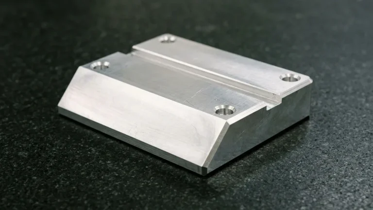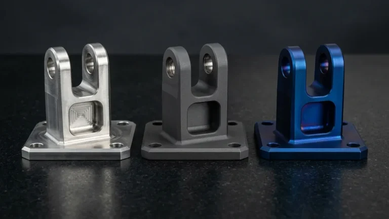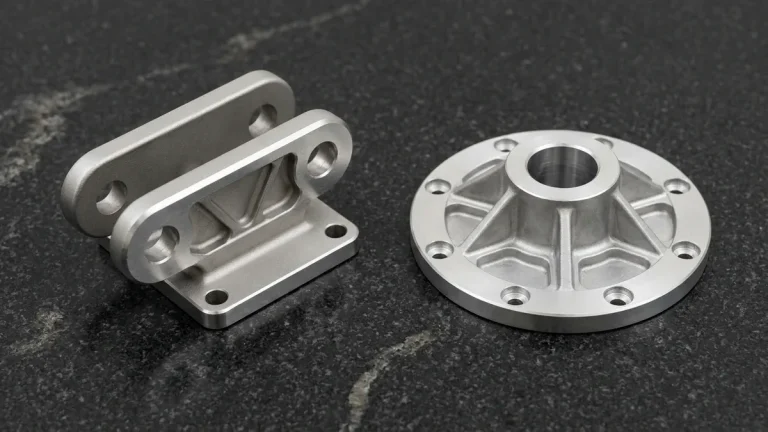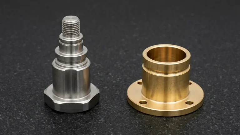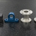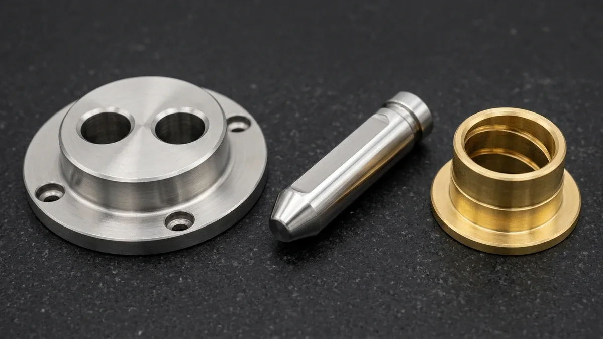
Press Fit vs Slip Fit defines the core mechanical boundary in cylindrical assembly design: whether a mating shaft and bore lock together via elastic interference or slide freely across a positive clearance gap. Under ISO 286 and ANSI B4.1 standards, misapplying these fits causes seized fixture plates or fretting fatigue.
From a contact mechanics perspective, a slip fit guarantees that the minimum bore diameter exceeds the maximum shaft diameter (Dmin > dmax), preserving kinematic freedom for sliding or rotation. Conversely, a press fit enforces a shaft larger than the bore (dmin > Dmax), transmitting torque through static interfacial friction.
In our in-house Computer Numerical Control (CNC) machining facility, we execute hole-basis H7 bores and precision shaft fits across 3-axis and 4-axis Vertical Machining Centers (VMCs), multi-axis CNC turning centers, and cylindrical grinders. Holding bearing journals and dowel pins to ±0.005 mm (±0.0002″) at Ra 0.2–0.4 µm guarantees first-article assembly.
Executive Summary & Engineering Takeaways (BLUF)
- ISO 286 Ø20 mm (H7 = +0.021 / 0 mm) Limits: Sliding slip fits (H7/g6, −0.007 / −0.020 mm) yield +7 to +41 µm clearance, locational slip fits (H7/h6, 0 / −0.013 mm) give 0 to +34 µm, transition fits (H7/k6, +0.015 / +0.002 mm) span +19 to −15 µm, and press fits (H7/p6, +0.035 / +0.022 mm) enforce −1 to −35 µm interference.
- Dual-Dowel Hybrid Fit Rule: Never specify H7/p6 press fits on both mating plates across two parallel pins; anchor pins in the baseplate with H7/p6 (1.5×D–2.5×D depth plus a Ø2.0 mm air vent) and ream the removable cover to H7/g6 paired with one cylindrical and one diamond-relieved pin.
- Pitch-Mismatch Relief & Bore Masking: Two solid cylindrical pins separated by a 0.015 mm (0.0006″) center-distance pitch error generate 872.66 N (196.2 lbf) of lateral binding; pair one cylindrical pin with one diamond-relieved pin (0.0111° yaw accuracy), hold Ra 0.2–0.8 µm, and plug-mask H7 bores before Type II/III anodizing.
- Anti-Galling & Lead Times: Pair 17-4PH H900 (40–44 HRC) or 440C (58–60 HRC) pins against 304/316L or C3604 brass to prevent cold-welding. We deliver CNC-machined prototypes in 4 to 8 business days and ground or anodized parts in 7 to 12 business days (Ex-Factory Production & Inspection Turnaround, separate from 3 to 5 days air transit).
Article Engineering Navigation
- 1. Slip Fit vs. Press Fit Fundamentals: How Do ISO 286 Hole-Basis (H7) Clearance, Transition, and Interference Zones Differ?
- 2. Quantitative Fit Selection Matrix: From Free-Running H8/f7 & Sliding H7/g6 to Heavy Interference H7/p6 & H7/s6
- 3. Why Do Dual-Dowel Fixture Plates Require a Hybrid Press-Fit (H7/p6) and Slip-Fit (H7/g6) Architecture?
- 4. CNC Boring, Reaming, Cylindrical Grinding & Surface Roughness (Ra) Controls for Precision Fits
- 5. Shop-Floor Failure Troubleshooting (Galling, Slip-Fit Cocking & Relief Undercuts)
- 6. The Engineering Verdict: When to Specify Slip Fit, Transition Fit, or Press Fit (Plus 20°C Metrology)
- 7. Technical Engineering FAQ
| Fit Category & ISO Class | Ø20 mm Bore & Shaft Limits | Clearance (+) / Interference (−) | Assembly Force & Cost Ratio | Tolerance & Roughness (Ra) | Recommended Application / When to Choose |
|---|---|---|---|---|---|
| Running Slip Fit (H8/f7 or H7/f7) | H7: +0.021 / 0 mm; f7: −0.020 / −0.041 mm | +20 to +62 µm (+20 to +74 µm in H8/f7) | Hand drop-in (0 N); 1.0x Baseline | ±0.012 mm; Ra 0.8–1.6 µm (32–63 µin) | Continuous rotation with oil film: C3604 brass bushings, idler shafts |
| Sliding Slip Fit (H7/g6) | H7: +0.021 / 0 mm; g6: −0.007 / −0.020 mm | +7 to +41 µm (+0.007 to +0.041 mm) | Thumb slide (10–30 N); 1.15x Baseline | ±0.008 mm; Ra 0.4–0.8 µm (16–32 µin) | Precision linear guiding and removable fixture covers over dowel pins |
| Locational Slip Fit (H7/h6) | H7: +0.021 / 0 mm; h6: 0 / −0.013 mm | 0 to +34 µm (0.000 to +0.034 mm) | Hand push (20–80 N); 1.15x Baseline | ±0.008 mm; Ra 0.4–0.8 µm (16–32 µin) | Non-rotating bearing outer rings in 6061/7075 housings, alignment spigots |
| Transition Fit (H7/js6 & H7/k6) | H7: +0.021 / 0 mm; k6: +0.015 / +0.002 mm | H7/js6: +27.5 to −6.5 µm; H7/k6: +19 to −15 µm | Soft mallet (0.3–2.5 kN); 1.25x Baseline | ±0.006 mm; Ra 0.4 µm (16 µin) | Concentric timing pulleys, keyed gear hubs, harmonic adapter spigots |
| Drive Press Fit (H7/p6) | H7: +0.021 / 0 mm; p6: +0.035 / +0.022 mm | −1 to −35 µm (−0.001 to −0.035 mm) | Arbor press (4–18 kN); 1.35x Baseline | ±0.005 mm; Ground Ra 0.2–0.4 µm | Permanent dowel anchoring in fixture bases, bronze bushing retention |
| Heavy Shrink Fit (H7/s6) | H7: +0.021 / 0 mm; s6: +0.048 / +0.035 mm | −14 to −48 µm (−0.014 to −0.048 mm) | Thermal/cryo shrink; 1.50x Baseline | ±0.005 mm; Ground Ra 0.2 µm (8 µin) | Keyless high-torque drive rotors, permanent steel wear collars |
1. Slip Fit vs. Press Fit Fundamentals: How Do ISO 286 Hole-Basis (H7) Clearance, Transition, and Interference Zones Differ?
An engineering fit under ISO 286-1 and ISO 286-2 defines the dimensional clearance or interference between a mating cylindrical hole and shaft sharing a basic diameter, classifying assemblies into slip, transition, or press zones by tolerance band overlap.
While general non-mating machined features follow ISO 2768-mK (±0.20 mm for 6–30 mm, ±0.30 mm for 30–120 mm), functional bearing seats, locating pins, and sliding bushings demand micron-level boundary control. Even a 12 µm deviation across a Ø20 mm interface converts a hand-sliding slip joint into an immovable press lock.
To standardize reamers and plug gauges on the shop floor, over 90% of assemblies specify the Hole-Basis System (anchoring the bore at H with lower deviation EI = 0.000 mm while varying the shaft from f–h slip to p–s press). Conversely, pre-ground ISO 8734 m6 dowel pins use the Shaft-Basis System (G7 slip or P7 press bores).
- Clearance Fits (Slip Fits — ISO Shafts a–h / ANSI B4.1 RC1–RC9 & LC1–LC11): Maximum shaft is smaller than or equal to minimum hole (
Δmin = Dmin − dmax ≥ 0at Maximum Material Condition (MMC)), providing positive clearance for oil films or tool-free disassembly. - Transition Fits (Locational Push Fits — ISO Shafts js–n / ANSI B4.1 LT1–LT6): Bore and shaft tolerance zones overlap, yielding either a micro-clearance or light elastic interference for concentric alignment of pulleys and gears.
- Interference Fits (Press & Shrink Fits — ISO Shafts p–zc / ANSI B4.1 LN1–LN3 & FN1–FN5): Minimum shaft exceeds maximum hole (
δmax = dmax − Dminat MMC), requiring pressing or thermal shrinking to generate contact pressure (p).
2. Quantitative Fit Selection Matrix: From Free-Running H8/f7 & Sliding H7/g6 to Heavy Interference H7/p6 & H7/s6
Quantitative fit selection under ISO 286-2 pairs a unilateral positive hole tolerance band—most commonly H7 (+0.021 / 0 mm at Ø20 mm), never miswritten bilaterally as ±0.010 mm—with an IT6 shaft deviation (13 µm width at Ø20 mm) to establish deterministic clearance or interference limits.
As shown in the ISO 286 Ø20.000 mm schematic below, pairing an H7 (+0.021 / 0 mm) bore with a g6 (−0.007 / −0.020 mm) shaft guarantees +7 to +41 µm sliding clearance. Conversely, switching the shaft to p6 (+0.035 / +0.022 mm) enforces −1 to −35 µm of press interference.
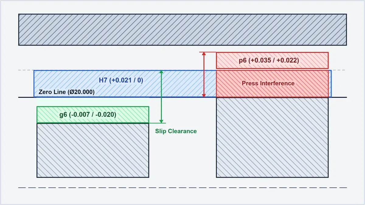
Because tolerance zone widths scale with the cube root of diameter under the ISO standard tolerance unit (i = 0.45 × ∛D + 0.001 × D in microns), engineers cannot apply identical micron allowances to a Ø8 mm pin and a Ø40 mm journal. Table 2 details exact ISO 286-2 deviations across three diameter ranges.
| ISO 286 Class & ANSI Equivalent | Ø6–10 mm Step (e.g., Ø8 mm) | Ø18–30 mm Step (e.g., Ø20 mm) | Ø30–50 mm Step (e.g., Ø40 mm) | Recommended Application / When to Choose |
|---|---|---|---|---|
| H8 / f7 (ANSI RC4 Running) | H8: +22/0; f7: −13/−28 µm → +13 to +50 µm | H8: +33/0; f7: −20/−41 µm → +20 to +74 µm | H8: +39/0; f7: −25/−50 µm → +25 to +89 µm | Lubricated bronze sleeve bearings, continuous rotary shafts (> 300 RPM) |
| H7 / g6 (ANSI RC1 Sliding) | H7: +15/0; g6: −5/−14 µm → +5 to +29 µm | H7: +21/0; g6: −7/−20 µm → +7 to +41 µm | H7: +25/0; g6: −9/−25 µm → +9 to +50 µm | Sliding spool valves, removable fixture covers over dowel pins |
| H7 / h6 (ANSI LC2 Snug Slip) | H7: +15/0; h6: 0/−9 µm → 0 to +24 µm | H7: +21/0; h6: 0/−13 µm → 0 to +34 µm | H7: +25/0; h6: 0/−16 µm → 0 to +41 µm | Stationary spigots, floating ball bearing outer rings in housings |
| H7 / k6 (ANSI LT2 Transition) | H7: +15/0; k6: +10/+1 µm → +14 to −10 µm | H7: +21/0; k6: +15/+2 µm → +19 to −15 µm | H7: +25/0; k6: +18/+2 µm → +23 to −18 µm | Concentric shaft couplings, timing pulleys, and keyed gear hubs |
| H7 / m6 (ANSI LT4 Tight Dowel) | H7: +15/0; m6: +15/+6 µm → +9 to −15 µm | H7: +21/0; m6: +21/+8 µm → +13 to −21 µm | H7: +25/0; m6: +25/+9 µm → +16 to −25 µm | Standard ISO 8734 hardened dowel pins, rotating inner bearing rings |
| H7 / p6 (ANSI FN2 Drive Press) | H7: +15/0; p6: +24/+15 µm → 0 to −24 µm | H7: +21/0; p6: +35/+22 µm → −1 to −35 µm | H7: +25/0; p6: +42/+26 µm → −1 to −42 µm | Permanent press-fit dowel anchors in fixture bases, bronze bushings |
| H7 / s6 (ANSI FN4 Heavy Shrink) | H7: +15/0; s6: +32/+23 µm → −8 to −32 µm | H7: +21/0; s6: +48/+35 µm → −14 to −48 µm | H7: +25/0; s6: +59/+43 µm → −18 to −59 µm | High-torque drive rotors and steel hubs via induction or cryo assembly |
Bearing Load Reversal & ISO 8734 m6 Pins: Under radial load on a rotating shaft, the inner bearing ring requires a k5, k6, or m6 fit to stop creep, while the outer ring uses H7/h6. Pre-ground ISO 8734 m6 pins (+8 to +21 µm at Ø20 mm) pair with P7 press and G7 slip bores.
3. Why Do Dual-Dowel Fixture Plates Require a Hybrid Press-Fit (H7/p6) and Slip-Fit (H7/g6) Architecture?
Dual-dowel fixture plates require a hybrid fit architecture—anchoring locating pins with an H7/p6 press fit in the baseplate while reaming H7/g6 slip bores in the removable cover—because pressing both plates onto two parallel pins over-constrains hole tolerances and doubles pull-out force.
Even on high-accuracy 3-axis VMCs holding hole-to-hole center distances within ±0.010 mm to ±0.015 mm (±0.0004″ to ±0.0006″), microscopic pitch and perpendicularity variations exist between two separately machined plates. When multi-hole center-to-center positional tolerances accumulate beyond ±0.015 mm (±0.0006″) across mating plates, reference our CNC machining tolerances and statistical RSS stack-up guide.
If an engineer specifies a tight interference fit on both the baseplate and the removable top plate, the two parallel dowel pins act as rigid cantilevers fighting against the hole-spacing delta. Furthermore, pressing a pin into an unvented blind bore compresses trapped air and oil, pushing the pin back out.
As shown in the cross-sectional Design for Manufacturability (DFM) schematic below, the optimal architecture pairs a permanent H7/p6 press-fit anchor bore in the baseplate (with a Ø2.0 mm bottom air vent and 1.5×D to 2.5×D depth) with a removable H7/g6 slip-fit cover bore (1.0×D to 1.5×D depth and a 15° pin lead-in).
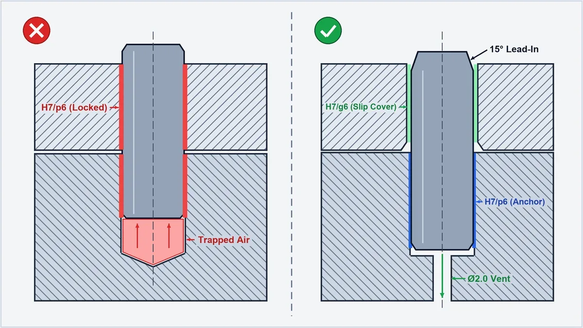
To eliminate lateral binding between the two slip-fit holes in the upper cover plate without sacrificing repeatability, pair one full cylindrical dowel pin (constraining X/Y translation) with one diamond-relieved dowel pin (constraining only rotational yaw θz while absorbing ±0.050 mm of center-distance variation; see our guide to precision locating and fastening pins).
📐 4-Step Quantitative Derivation: Ø10 mm Dual-Dowel Pitch Cantilever Binding Force, Diamond-Pin Yaw Accuracy & Cover Pull-Out Force
- Step 1 — Input Geometry & ISO 286-2 Limits (Illustrative Case): Two parallel
Ø10.000 mm (0.3937″)hardened 440C stainless dowel pins (E = 200,000 MPa, area moment of inertiaI = π × D⁴ / 64 = 490.87 mm⁴, engagement overhangL = 15.0 mm, center-to-center pin spanS = 150.0 mm / 5.9055″, static frictionμ = 0.15) locate two 6061-T6 fixture plates machined with a hole-pitch deltaδpitch = 0.015 mm (15.0 µm). ISO 286-2 limits (Ø6–10 mmstep): BoreØ10 H7 = +0.015 / 0 mm(Dmin = 10.000 mm,Dmax = 10.015 mm); slip-fit journalØ10 g6 = −0.005 / −0.014 mm(dmin = 9.986 mm,dmax = 9.995 mm); press-fit anchorØ10 p6 = +0.024 / +0.015 mm. - Step 2 — Governing Equations (Slip Window, Cantilever Pitch Binding, Yaw Repeatability & Extraction Force):
• Slip-Fit Clearance Window (H7/g6):ΔCmin = Dmin − dmaxandΔCmax = Dmax − dmin
• Cantilever Lateral Binding Force (Two Full Cylindrical Pins at MMC,δdeflect = δpitch − ΔCmin):Fbind = (3 × E × I × δdeflect) / L³
• Angular Yaw Repeatability Across SpanS(Cylindrical + Diamond Pin):Δθmax = ΔCmax / S(radians)
• Axial Cover Disassembly Pull Force:Fpull = Npins × π × D × L × peff × μ - Step-by-Step Hand Calculation:
• H7/g6 Slip Clearance Window:ΔCmin = 10.000 − 9.995 = +0.005 mm (+5.0 µm);ΔCmax = 10.015 − 9.986 = +0.029 mm (+29.0 µm).
• Why Two Full Cylindrical Pins Jam Under a 15 µm Pitch Delta: At MMC, the15.0 µmhole-spacing error exceeds the5.0 µmminimum slip clearance byδdeflect = 15.0 − 5.0 = 10.0 µm (0.010 mm). Forcing the cover over two solid cylindrical pins bends the pin as a cantilever with lateral forceFbind = (3 × 200,000 × 490.87 × 0.010) / 15.0³ = 2,945,220 / 3,375 = 872.66 N (196.2 lbf), galling the reamed aluminum bore!
• Diamond-Relieved Secondary Pin Yaw Repeatability: Replacing the second pin with a diamond-relieved dowel absorbs up to±0.050 mmalong the center-line axis (Fbind = 0 N) while restricting rotational yaw across the150.0 mmspan toΔθmax = 0.029 / 150.0 = 0.0001933 rad = 0.0111° (39.9 arcseconds).
• Dual H7/p6 Press vs. Hybrid Cover Pull-Out Force: At an effective press interface pressurepeff = 55.0 MPa, oneØ10 × 15 mmpin requiresFaxial,1 = 3.1416 × 10.0 × 15.0 × 55.0 × 0.15 = 3,887.7 N (3.89 kN). Pressing both plates withH7/p6demands2 × 3.89 kN = 7.78 kN (1,748 lbf)to pry off the cover, whereas the hybridH7/p6base +H7/g6cover design drops manual cover lift-off force below15 N.
Shop-Floor Engineering Verdict: Anchoring both pins in the baseplate with Ø10 H7/p6 (7.78 kN retention) while reaming Ø10 H7/g6 slip bores in the removable cover paired with one cylindrical and one diamond-relieved pin eliminates 872.66 N of pitch-binding seizure and holds 0.0111° (39.9″) angular repeatability with effortless hand removal.
For Lamé thick-walled cylinder contact pressure (p), DIN 7190 asperity flattening loss (Δδ = 1.2 × [Rah + Ras]), and thermal shrink heating limits (≤ 100–110°C for 7075-T651), consult our press-fit tolerance and Lamé stress calculation guide.
4. CNC Boring, Reaming, Cylindrical Grinding & Surface Roughness (Ra) Controls for Precision Fits
Achieving true ISO 286 IT6 and IT7 fit zones requires matching each tolerance band to the correct subtractive finishing process—specifically single-point precision boring or carbide reaming for H7 holes and CNC turning or precision cylindrical grinding for g6, h6, k6, and p6 shafts—while controlling surface roughness under ISO 4287 (ASME B46.1).
Standard two-flute twist drills wander radially and produce out-of-round holes with tolerances of ±0.050 to ±0.100 mm and rough walls (Ra 3.2–6.3 µm). Instead, our machinists execute a four-stage hole-making sequence on 3-axis and 4-axis VMCs (see our CNC precision hole-making and boring process guide):
- Spot Drilling & Helical Roughing: Spot-drill a 90° or 142° pilot seat to prevent chisel-edge walk, then drill or helically interpolate the bore leaving a uniform radial stock allowance of 0.15 mm to 0.25 mm (0.006″ to 0.010″) per side.
- Single-Point Fine Boring (True Position & Cylindricity Correction): Because a flexible reamer follows a pre-drilled hole axis, critical bearing seats are finished with a micro-adjustable single-point carbide boring head (
Vc = 200–350 m/minin aluminum,80–130 m/minin stainless; feedf = 0.03–0.06 mm/rev) to hold cylindricity (⌭) within 0.004 to 0.008 mm. - 6-Flute Carbide Machine Reaming (High-Repeatability H7 Dowel Bores): For standardized dowel pin holes (Ø3.0 mm to Ø20.0 mm), plunge a floating-holder 6-flute solid carbide reamer at reduced speed (
Vc = 15–30 m/minin steels,40–70 m/minin aluminum; feedf = 0.10–0.25 mm/rev) with flood emulsion coolant to achieve H7 (+0.012 to +0.021 mm) and Ra 0.4–0.8 µm (16–32 µin). - External CNC Turning & Cylindrical Grinding (IT5/IT6 Shafts): While precision CNC turning with a 0.4 mm nose-radius cermet insert holds f7/g6/h6 tolerances (±0.006 to ±0.010 mm, Ra 0.8 µm), hardened press-fit pins requiring k6, m6, p6, or s6 within ±0.005 mm (±0.0002″) undergo plunge cylindrical grinding on Okamoto grinders to achieve Ra 0.2–0.4 µm (8–16 µin).
How Surface Coatings Alter H7/g6 and H7/p6 Fit Clearances: MIL-A-8625 Type II anodizing (10–25 µm thickness) shrinks an H7 bore diameter by 0.010 to 0.025 mm and binds an H7/g6 slip shaft, whereas ASTM A967 passivation on stainless steel forms a ~0.002 µm oxide film with zero dimensional change.
Because MIL-A-8625 Type III hardcoat anodizing (50 µm total film, 450–550 HV0.05 hardness) penetrates 50% inward and grows 50% outward—shrinking H7 bores by 0.050 mm—review our dedicated aluminum anodizing masking and dimensional allowance engineering guide.
| Machining or Surface Process | Target Feature & ISO Fit | Tolerance / Dimensional Shift | Roughness (Ra µm / µin) | Shop-Floor DFM & Masking Protocol |
|---|---|---|---|---|
| 6-Flute Solid Carbide Reaming | Ø3–20 mm H7 dowel & bushing bores | +0.012 to +0.021 mm (IT7) | Ra 0.4–0.8 µm (16–32 µin) | Leave 0.15–0.25 mm radial stock and 2.5 mm bottom blind chip clearance |
| Single-Point Fine Boring | Ø15–150 mm H6/H7/K7 bearing seats | +0.011 to +0.025 mm (IT6–IT7; ±0.005 mm repeatability) | Ra 0.4–0.8 µm (16–32 µin) | Corrects center-distance true position and bore cylindricity (≤ 0.005 mm) |
| Plunge Cylindrical Grinding | Hardened g6, h6, k6, m6, p6, s6 shafts | ±0.003 to ±0.005 mm (IT5–IT6) | Ra 0.2–0.4 µm (8–16 µin) | Machine a DIN 509 relief undercut at shaft shoulders for full wheel clearance |
| MIL-A-8625 Type II / III Anodizing | 6061-T651 & 7075-T651 aluminum hubs | Shrinks bore by 0.010–0.050 mm | Ra 1.2–2.0 µm if unmasked | Plug-mask all H7 bearing and dowel bores with high-temp silicone bungs |
| Electroless Nickel vs. Passivation | 4140 steel & 304/17-4PH stainless | ENP: −0.020 mm; Passivation: 0.000 mm | Preserves Ra 0.2–0.8 µm | Mask bores for ENP; apply ASTM A967 passivation with zero masking |
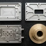
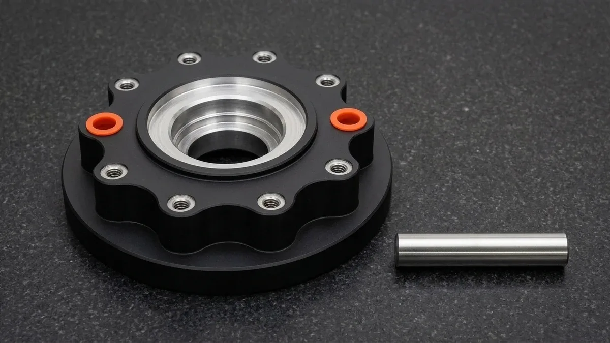
In our in-house 3-axis and 4-axis CNC milling practice, when producing black Type II anodized 7075-T651 harmonic drive adapter flanges, we insert custom silicone masking plugs into the central H7 bearing seat and symmetrical reamed dowel holes before racking, then verify the bare metallic bores with a calibrated steel pin gauge after sealing (as shown below).
5. Shop-Floor Failure Troubleshooting (Galling, Slip-Fit Cocking & Relief Undercuts)
Preventing catastrophic assembly failures during press-fit and slip-fit integration requires controlling three shop-floor failure mechanisms: adhesive cold-welding (galling) in stainless steel interfaces (requiring a ≥ 50 HB hardness differential), self-locking cocking in short sliding bushings (requiring L/D ≥ 1.2), and shoulder interference from missing DIN 509 relief undercuts.
Case 1: Austenitic Stainless Steel Press-Fit Galling & Cold-Welding
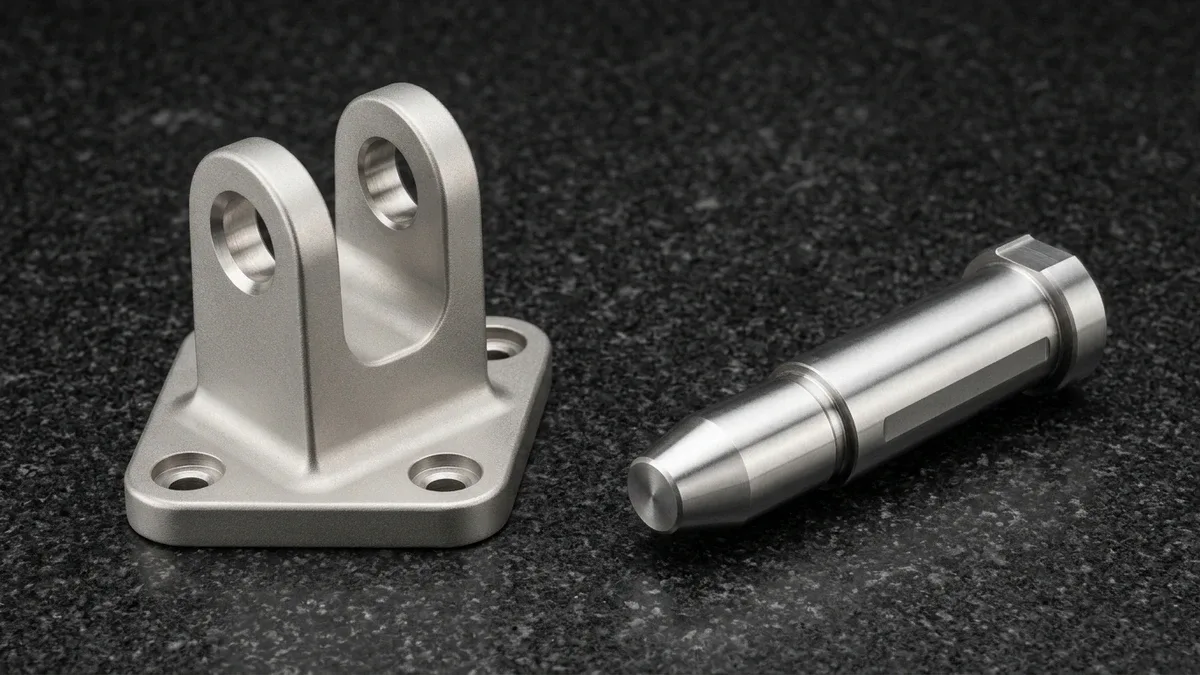
Symptom & Root Cause: Pressing a Ø12.000 mm p6 304 stainless pin into a 304 stainless clevis yoke spiked arbor press force from 6 kN to 28 kN and seized mid-stroke, because identical annealed austenitic stainless steels (~160 HB) wipe away their passive oxide layer under shear and cold-weld instantaneously.
Corrective Action: Enforce a hardness differential of ≥ 50 HB (5–10 HRC) by pairing a passivated 17-4PH H900 clevis yoke (40–44 HRC) with a cylindrical-ground 4140 alloy steel (28–32 HRC) or 440C (58–60 HRC) shoulder pin featuring a 15° × 2.0 mm lead-in cone (see our metal galling prevention guide).
Case 2: Slip-Fit Linear Bushing Cocking (L/D < 1.2) & Shoulder Fillet Interference
Slip-Fit Cocking Symptom & Fix: Short H7/g6 sliding bushings with engagement ratios below L/D = 1.0 jam under off-axis loads when tilting enters the self-locking friction cone (L < 2μD). Maintain sliding engagement length at L/D ≥ 1.2 to 2.0 and machine a DIN 509 Type E or F relief undercut at shaft shoulders so mating faces seat flush.
When pressing anchor dowels into blind baseplate bores, always drill a Ø1.5 to Ø2.0 mm bottom air-escape vent hole or mill a 0.3 mm axial bleed flat as detailed in our press-fit DFM guide above.
6. The Engineering Verdict: When to Specify Slip Fit, Transition Fit, or Press Fit (Plus 20°C Metrology)
Selecting between a slip fit (+7 to +74 µm clearance at Ø20 mm), transition fit (+19 to −15 µm), and press fit (−1 to −48 µm interference) requires balancing kinematic motion, disassembly frequency, torsional load, and operating temperature across four distinct engineering scenarios:
- Scenario A — Continuous Rotation or Linear Sliding Guidance (Choose H8/f7 or H7/g6 Slip Fit): When shafts rotate inside C3604 brass, tin-bronze, or PEEK bushings, or when guide rods translate inside linear blocks, specify H8/f7 (+20 to +74 µm at Ø20 mm) for oil-lubricated bearings and H7/g6 (+7 to +41 µm) for low-play linear guidance.
- Scenario B — High-Concentricity Location with Field Disassembly (Choose H7/h6 Slip or H7/k6 Transition Fit): For removable fixture covers, modular sensor heads, and timing pulleys requiring radial runout (↗) within 0.010 mm yet periodic maintenance removal, specify H7/h6 (0 to +34 µm) for hand push-assembly or H7/k6 (+19 to −15 µm) supplemented with a mechanical retaining ring or pinch clamp.
- Scenario C — Permanent Rigidity, Dowel Anchoring & Torque Transfer (Choose H7/p6 or H7/s6 Press Fit): When anchoring hardened locating dowel pins into fixture baseplates, seating thin-walled bronze bushings, or locking rotor hubs without keyways, specify H7/p6 (−1 to −35 µm at Ø20 mm) for hydraulic press assembly or H7/s6 (−14 to −48 µm) for thermal shrink-fit assembly.
- Scenario D — When to Avoid Standard Press Fits: Never press-fit into unmasked Type II/III anodized bores (oxide micro-cracks); never rely on a light H7/p6 steel-in-aluminum press fit above 80°C (a ΔT = 60°C rise with
αAl ≈ 23.1 × 10⁻⁶/Kvs.αsteel ≈ 11.5 × 10⁻⁶/Kcreates +0.021 mm differential bore expansion at Ø30 mm); and avoid un-knurled press fits in unfilled POM/PA66 plastics due to creep relaxation.
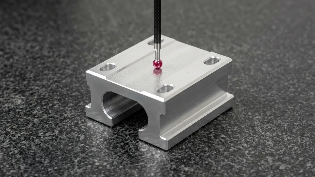
In our 20°C ± 1°C metrology laboratory, we never use Vernier calipers to inspect ISO 286 IT6/IT7 fits because Abbe error exceeds ±0.020 mm. To verify bore diameter within ±0.005 mm (±0.0002″) and cylindricity (⌭) within 0.005 mm via Coordinate Measuring Machine (CMM) and Geometric Dimensioning and Tolerancing (GD&T) protocols, see our CMM metrology and GD&T verification guide.
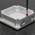
After ultrasonic cleaning and 4-hour thermal stabilization at 20°C, our inspectors verify H7 holes with Class ZZ/X cylindrical Go/No-Go steel pin gauges and three-point internal bore micrometers (detecting three-lobed out-of-roundness), measure ground shafts with 0.001 mm ratchet micrometers, and probe datum flatness and bore coordinates on a Zeiss bridge CMM using a vertical D4mm ruby stylus (as shown below).
🔗 Related CNC Machining & Precision Fit Engineering Guides
- Calculate thick-wall cylinder hoop stress and thermal shrink-fit temperatures in our Press-Fit Tolerance, Lamé Contact Pressure & Thermal Assembly Guide.
- Compare cylindrical, diamond-relieved, and tapered locator geometries in our Engineering Guide to Precision Dowel, Taper & Clevis Pins.
- Master multi-stage drilling, single-point boring, and carbide reaming in our Precision CNC Hole-Making, Boring & Reaming DFM Guide.
- Prevent cold-welding during stainless steel assembly with our Metal Galling Root Causes, Hardness Pairing & Anti-Seize Guide.
- Explore our Precision CNC Turning Services and Cylindrical & Surface Grinding Capabilities for ±0.005 mm shaft and bore fabrication.
7. Technical Engineering FAQ
At Ø20.000 mm nominal diameter, an H7/g6 slip fit guarantees +0.007 to +0.041 mm (+7 to +41 µm) of positive clearance for smooth hand movement. Conversely, an H7/p6 press fit enforces −0.001 to −0.035 mm (−1 to −35 µm) of diametral interference requiring mechanical pressing.
Press-fitting both plates across two parallel dowel pins locks minor hole-center positional tolerances (±0.010 to ±0.015 mm) into lateral binding and doubles extraction force. Anchoring pins in the baseplate with H7/p6 while reaming H7/g6 slip bores in the cover guarantees repeatable alignment and tool-free disassembly.
Whenever two parallel locating holes are machined separately with standard ±0.010 to ±0.015 mm (±0.0004″ to ±0.0006″) center-distance tolerances, two full cylindrical pins over-constrain the plate and bind during sliding. Pairing one cylindrical pin with one diamond-relieved pin absorbs longitudinal pitch error while locking angular yaw within 0.0111°.
Yes, MIL-A-8625 Type II anodizing shrinks internal bore diameters by 0.010 to 0.025 mm, while Type III hardcoat shrinks bores by 0.050 mm from oxide build-up. Always specify high-temperature silicone plug masking on H7 bearing seats and dowel holes to preserve ISO 286 fit tolerances.
Validate Your ISO 286 Shaft & Bore Fit Tolerances Before Cutting Metal
Upload your 3D CAD models (STEP/IGES) and 2D engineering drawings for a complimentary ISO 286 shaft-and-bore fit review, anodizing masking evaluation, and custom production quotation across CNC turning, precision boring, carbide reaming, and cylindrical grinding.
Upload 3D CAD for DFM Review & Custom Quote →