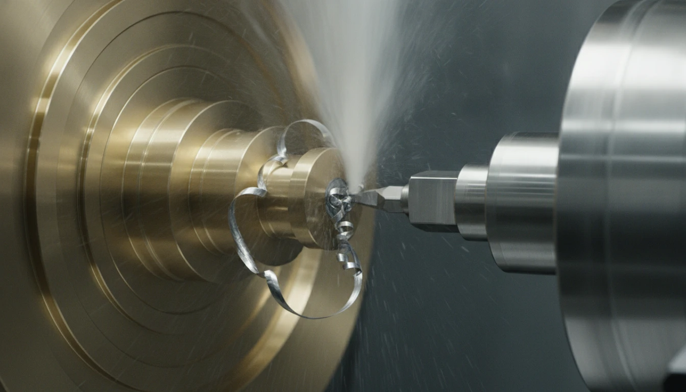
In high-precision manufacturing, standard CNC milling and turning are celebrated for holding tolerances within ±0.01 mm (±10 μm) and achieving surface finishes around Ra 0.8 μm. Yet in photonics, head-up display (HUD) automotive optics, laser collimation systems, infrared thermal imaging, and semiconductor lithography, 10 microns of deviation represents an intolerable chasm. These applications demand optical figure accuracy measured in fractions of a light wavelength (λ/10) and surface roughness values below 2 to 5 nanometers (Ra ≤ 0.005 μm)—mirror-like finishes so pristine that light passes through or reflects with zero optical scatter.
Historically, achieving such optical finishes required weeks of manual pitch lapping, robotic polishing, and abrasive diamond paste compounding. While effective for simple spherical glass geometries, classical polishing cannot cost-effectively produce freeform aspheric contours, micro-lens arrays, or thin-walled metal reflectors. Enter Ultra-Precision Diamond Machining (UPDM)—encompassing Single-Point Diamond Turning (SPDT), Diamond Fly Cutting, and 5-Axis Diamond Micro-Milling. By pairing natural monocrystalline diamond cutting tools with aerostatic machine kinematics, UPDM cuts optical surfaces directly to net shape with zero post-machining polishing required.
In this comprehensive engineering guide, AS Prototypes explores the physics, tool crystallography, kinematic machine requirements, material compatibility rules, and metrology protocols that govern ultra-precision diamond machining.
The Physics of Nanometer Surface Generation: Ductile-Regime Cutting
How does a physical cutting tool generate an optical mirror finish without leaving micro-fractures, tearing, or tooling chatter marks? The answer lies in the mechanics of ductile-regime machining.
When cutting depth is reduced to the sub-micron scale (often under 200 nanometers), the shear stress induced beneath the diamond tool’s razor-sharp cutting edge exceeds the yield stress of the material before reaching its fracture limit. Even notoriously brittle semiconductors and infrared optical crystals—such as single-crystal Silicon (Si) and Germanium (Ge)—transition from brittle catastrophic fracture into plastic ductile flow. Instead of micro-cracking and chipping, the material forms continuous, ribbon-like chips identical to soft brass, leaving a virgin, crack-free optical surface.
To sustain ductile-regime machining, machine tools must achieve extreme structural stability:
- Aerostatic Air-Bearing Spindles: Spindle radial and axial runout must not exceed < 25 nanometers, completely isolating the cut from motor vibration.
- Hydrostatic Oil Guideways & Linear Motors: Frictionless hydrostatic slideways powered by brushless linear motors and sub-nanometer holographic optical scales eliminate stick-slip friction down to 1-nanometer positioning resolution.
- Active Pneumatic Vibration Dampening: The entire machine casting (frequently polymer composite granite) floats on active pneumatic isolators tuned to filter out ambient factory floor frequencies (< 2 Hz).
Diamond Tooling Crystallography: SCD vs. PCD vs. CVD
Not all diamond cutting tools are created equal. The mechanical performance and achievable surface roughness vary drastically depending on the crystal structure of the diamond insert:
1. Single-Crystal Diamond (SCD / Monocrystalline Natural or HPHT)
The gold standard for ultra-precision optics. Monocrystalline diamond tools are cleaved and polished from defect-free natural gem-quality diamonds or synthetic High-Pressure High-Temperature (HPHT) single crystals along specific crystallographic planes (typically the (110) or (100) plane):
- Edge Radius: Cutting edge radius ($r_e$) is sharpened to less than 5 to 10 nanometers—essentially an edge only a few dozen carbon atoms wide.
- Optical Mirror Capability: Only SCD tools can produce true nanometer surface roughness (Ra ≤ 2.0 nm) and specular reflectance across visible light spectrums.
2. Polycrystalline Diamond (PCD)
PCD consists of randomly oriented micron-sized synthetic diamond crystals sintered together with a cobalt catalytic binder under ultra-high pressure. PCD offers supreme toughness and impact resistance, making it the premier choice for high-volume machining of abrasive high-silicon aluminum alloys (e.g., A380, ADC12), carbon fiber composites (CFRP), and metal matrix composites (MMC). However, because PCD tools wear unevenly along micro-grain boundaries, they cannot produce nanometer optical mirror finishes; typical finishes are limited to Ra 0.1 to 0.3 μm.
3. Chemical Vapor Deposition (CVD) Diamond Coatings
CVD diamond is grown as a thin polycrystalline diamond film (5 to 20 μm thick) onto tungsten carbide tool shanks. Highly economical for micro-end mills cutting abrasive graphite EDM electrodes, green-state ceramics, and dental zirconia.
Core Ultra-Precision Diamond Machining Processes
1. Single-Point Diamond Turning (SPDT)
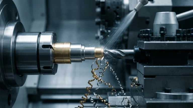
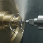
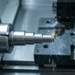
SPDT is the rotational turning of rotationally symmetric or mildly off-axis optics. A stationary SCD diamond tool faces a rapidly spinning workpiece held on a vacuum chuck. SPDT directly cuts complex optical profiles—including aspheric lenses, off-axis parabolic (OAP) mirrors, and diffractive Fresnel optics—with sub-micron form accuracy (PV ≤ 0.15 μm) and nanometer roughness.
2. Diamond Fly Cutting & Planar Milling
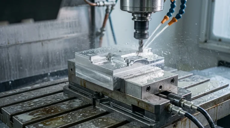
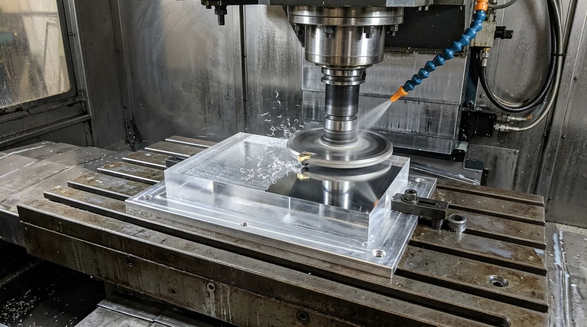
For flat mirrors, polygon scanner prisms, optical windows, and light guide blocks, fly cutting employs a large-diameter rotating cutter body (typically 100 to 250 mm diameter) housing one or two SCD diamond inserts. As the fly cutter sweeps across a slowly translating substrate of PMMA, Polycarbonate, or Aluminum, it generates a perfectly planar surface with zero optical distortion and pristine transparency.
3. Fast Tool Servo (FTS) & Slow Tool Servo (STS) Freeform Machining
Standard turning is limited to rotational symmetry. Fast Tool Servo (FTS) integrates a high-bandwidth piezoelectric actuator behind the diamond tool, vibrating the cutter in and out in real time (up to 1,000 Hz) synchronized with spindle C-axis rotation. This enables direct machining of non-rotationally symmetric optical surfaces, such as progressive eyeglass lenses, toroidal mirrors, and multi-focal micro-lens arrays.
The Ferrous Metal Chemical Limitation: Catalytic Graphitization
A critical, non-negotiable rule of diamond machining: Diamond cutting tools must NEVER be used to cut ferrous metals (carbon steel, tool steel, stainless steel) or nickel-based superalloys (Inconel).
The limitation is not mechanical hardness—diamond is vastly harder than any steel. Rather, it is chemical affinity: diamond is pure crystalline carbon ($sp^3$ hybridization). At the localized high temperatures and pressures generated at the cutting interface (> 700°C), iron acts as an aggressive chemical catalyst, triggering rapid graphitization of the diamond tool into soft graphite ($sp^2$ carbon). Simultaneously, carbon atoms rapidly diffuse from the diamond tool into the iron lattice. Within seconds of contact with steel, a $1,500 diamond tool edge is chemically destroyed.
How AS Prototypes Solves the Steel Tooling Challenge:
- Electroless Nickel Plating (NiP) Diamond Turning: For optical injection mold inserts requiring hardened steel bases, we machine a pre-hardened 420 stainless steel core, plate it with a 100 μm layer of high-phosphorus (10% to 13% P) electroless nickel, and diamond-turn the amorphous nickel layer to an optical finish (Ra ≤ 1.5 nm).
- Precision Cubic Boron Nitride (CBN) Machining: For direct hardened steel machining, we utilize ultra-precision CBN tools, which remain chemically inert against iron at elevated cutting temperatures.
Material Compatibility Guide for Diamond Machining
- Non-Ferrous Optical Metals:
- Aluminum 6061-T6 / Rapid Solidification Aluminum (RSA 6061): Outstanding machinability. RSA alloys feature ultra-fine grain size, eliminating comet-tail micro-defects around intermetallic precipitates.
- Oxygen-Free High-Conductivity Copper (OFHC Cu): The premier substrate for high-energy CO2 laser mirrors and synchrotron radiation monochromators.
- Optical Brass (CuZn39Pb3): Flawless chip formation for watch movements and precision slit apertures.
- Optical Polymers:
- Polymethyl Methacrylate (PMMA / Acrylic): 92% light transmittance, excellent diamond machinability for prototype automotive headlamp lenses and HUD combiners.
- Polycarbonate (PC): High impact resistance for rugged optical windows; requires razor-sharp SCD cutters to prevent optical stress birefringence.
- Cyclic Olefin Polymers (COP / Zeonex / Topas): Ultra-low moisture absorption and low birefringence for medical diagnostic microfluidic chips and smartphone camera lens prototypes.
- Infrared Crystals & Semiconductors:
- Single-Crystal Germanium (Ge) & Silicon (Si): Thermal imaging lenses (8 to 14 μm FLIR optics) diamond-turned under strict ductile-regime feed rates (≤ 1.5 μm/rev).
- Zinc Selenide (ZnSe) & Calcium Fluoride (CaF2): Multi-spectral laser windows and UV excimer optics.
Engineering Comparison: Diamond Machining vs. Alternative Finishing
| Machining Process | Tool Edge Sharpness | Achievable Surface Roughness (Ra) | Form Accuracy (PV Wavefront) | Geometric Freedom | Post-Polishing Requirement |
|---|---|---|---|---|---|
| Standard Carbide CNC Machining | 5.0 to 10.0 μm | 0.4 to 1.6 μm | ±5.0 μm | Full 3D / 5-Axis | Mandatory (Extensive abrasive polishing) |
| PCD Tool Precision Machining | 1.0 to 3.0 μm | 0.1 to 0.3 μm | ±2.0 μm | Full 3D / 5-Axis | Required for optical transparency |
| Ultra-Precision SPDT / Diamond Milling | < 5 to 10 nm (Atomically sharp) | 1.5 to 5.0 nm (Mirror quality) | < 0.15 μm (λ/6 to λ/10) | Aspheric, Off-Axis Parabolic, Freeform | ZERO Polishing Required (Direct Optical Net Shape) |
| Traditional Pitch Lapping & Polishing | N/A (Free abrasive slurry) | 1.0 to 3.0 nm | < 0.05 μm (λ/20) | Limited to Spherical & Planar Flats | Inherent to process (Extremely slow cycle time) |
Metrology Verification: Certifying Sub-Nanometer Quality
You cannot manufacture what you cannot measure. At AS Prototypes, our ultra-precision diamond machining center operates within an environmentally controlled cleanroom (temperature stabilized to ±0.2°C). Every optical workpiece is verified using state-of-the-art metrology instruments:
- Zygo Optical White-Light Interferometry: Quantifies non-contact 3D surface roughness (Ra, Rq, Rz) down to sub-nanometer resolution, certifying that optical scatter remains below critical thresholds.
- Laser Fizeau Form Interferometry: Measures Peak-to-Valley (PV) wavefront error across the complete optical aperture, providing false-color interferometric fringe maps comparing the physical part against nominal CAD aspheric equations.
- Taylor Hobson Contact Profilometry: High-resolution mechanical stylus mapping for steep-angle optical flutes and micro-grooves where optical interferometers lose fringe contrast.
At localized cutting temperatures exceeding 700°C, iron acts as a catalytic agent, triggering rapid chemical graphitization of the diamond sp3 crystal lattice into soft sp2 graphite. Furthermore, rapid carbon diffusion into the steel matrix destroys the microscopic cutting edge within seconds.
Toolmakers apply a 100 to 150 µm layer of amorphous high-phosphorus electroless nickel (10% to 13% P) onto the hardened stainless steel substrate. SPDT diamond flycutting or turning is then performed directly on the nickel layer, achieving Ra below 1.5 nm.
When the depth of cut is kept below the critical threshold (typically under 100 to 200 nanometers), brittle materials like silicon and germanium deform via plastic shear flow rather than brittle fracture propagation, yielding crack-free optical surfaces.
Engineer Optical-Grade Precision with AS Prototypes
Whether your application demands direct single-point diamond turned (SPDT) infrared lenses, optical-grade PMMA light guides, high-purity aluminum laser reflectors, or diamond-turned nickel mold inserts, AS Prototypes delivers the sub-micron kinematic accuracy and nanometer surface finishes your engineering designs require.
Our dedicated ultra-precision metrology and manufacturing engineers conduct comprehensive DFM evaluations on every optical CAD file—optimizing tool centerlines, vacuum chucking datums, and cutting parameters before cutting the first pass.
Submit Your Optical CAD Models for Instant Diamond Machining DFM & Quote →