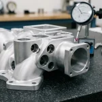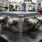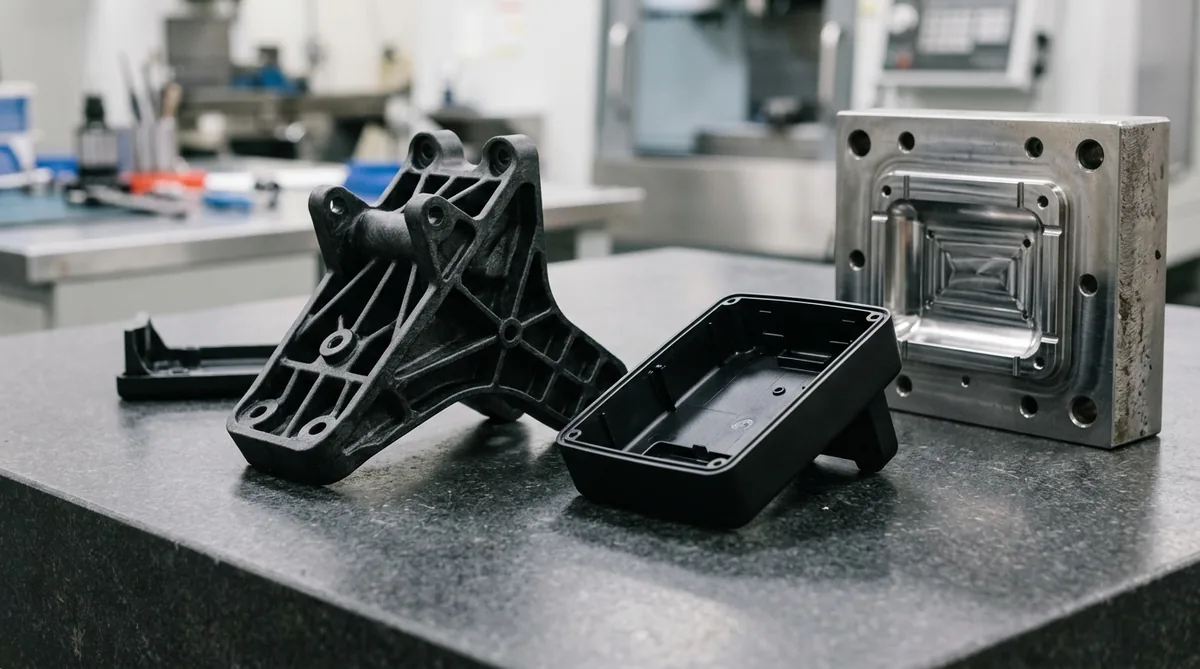
Overcoming persistent plastic injection molding problems requires a rigorous understanding of polymer melt rheology, tool design mechanics, and thermodynamic cooling equilibrium. When transitioning thermoplastic components from rapid prototyping into high-volume manufacturing, subtle tooling flaws or improper processing windows can generate costly structural and aesthetic failures. At our in-house injection molding tooling and rapid production facility, our tooling engineers diagnose mold performance down to the micron to ensure flawless execution across every press cycle.
Anatomy of Injection Molding Failures: Melt Rheology and Mold Mechanics
Modern injection molding relies on balancing high-pressure viscous melt flow with rapid heat extraction inside hardened tool steel cavities. Polymers exhibit viscoelastic behavior, where melt viscosity fluctuates dynamically with shear rate and melt temperature. When tool cavities are improperly gated, insufficiently vented, or poorly cooled, severe defects inevitably manifest.
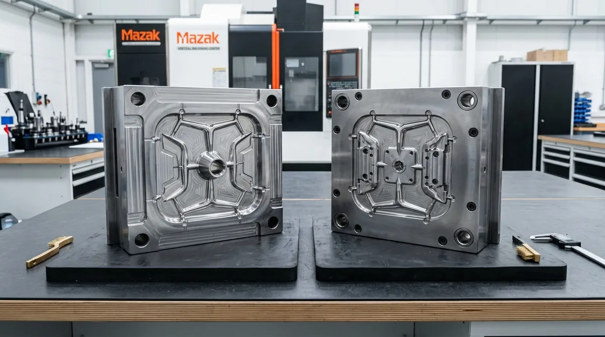
Achieving defect-free molded components demands tight coordination between mold design, precision precision CNC mold core machining, and scientific molding process parameter control.
Defect 1: Sink Marks and Internal Voids in Thick Cross-Sections
Sink marks are localized surface depressions that form directly over thick structural features, such as structural ribs, mounting bosses, or solid wall transitions. As the molten plastic cools from the mold wall inward, the outer perimeter solidifies first while the core remains molten. When the internal volume shrinks during phase change from liquid to solid, the solidified outer shell is pulled inward by thermal contraction.
- Internal Voids vs. Sink Marks: In rigid resins with high tensile skin strength (such as unreinforced PC or PMMA), the solid skin resists inward collapse. Instead, vacuum voids develop within the center of the cross-section, causing severe internal stress concentrations and optical distortion.
- DFM Wall Thickness Rule: Structural ribs must not exceed 40% to 60% of the nominal wall thickness. Nominal walls should remain uniform throughout the component (within ±10% maximum deviation).
- Packing Pressure Dynamics: Inadequate packing pressure or premature gate freeze-off prevents supplemental melt from replenishing volumetric shrinkage during the crystallization phase.
Defect 2: Mold Flash and Parting Line Mismatch
Flash consists of thin plastic films extending beyond the intended geometry along parting lines, slide shutoffs, or ejector pin clearance bores. It occurs when injection or cavity pressure exceeds the machine’s hydraulic or electric clamp tonnage, or when mold steel deflects under load.
- Parting Line Wear & Tool Deflection: Repeated cycles on soft aluminum or unhardened P20 molds cause parting line fatigue. Our facility machines mold bases and inserts from hardened S136 (48-52 HRC) or NAK80 to resist micro-deflection under 350 to 800 bar cavity pressures.
- Venting Channel Depth: Vent depths must be precisely tuned to the resin’s melt flow index (MFI). For low-viscosity resins like PA66 or POM, vent depths must not exceed 0.015 mm, whereas high-viscosity resins like PC accommodate 0.03 to 0.04 mm vents without flashing.
- Clamp Tonnage Calculation: Ensure clamp tonnage provides at least a 20% safety margin over calculated projected area force: F_clamp = A_projected * P_cavity * 1.2.
Defect 3: Warpage and Differential Volumetric Shrinkage
Warpage manifests as dimensional twisting, bow, or out-of-flatness in molded parts after demolding. It is caused by non-uniform volumetric shrinkage across different regions of the part geometry.
- Cooling Channel Imbalance: If the core side cools slower than the cavity side, differential thermal contraction creates bending moments that warp the part toward the hotter mold half.
- Fiber Orientation in Reinforced Resins: Glass-fiber-filled resins (such as PA66-GF30) shrink anisotropically: longitudinal shrinkage along melt flow lines is significantly lower (~0.3%) than transverse shrinkage perpendicular to flow (~0.9%). Gate placement must be strategically engineered to guide fiber orientation along functional stress planes.
- Uniform Cooling Architecture: Implementing CNC-milled conformal cooling baffles ensures cycle-to-cycle core temperature variance remains within ±1.5°C.
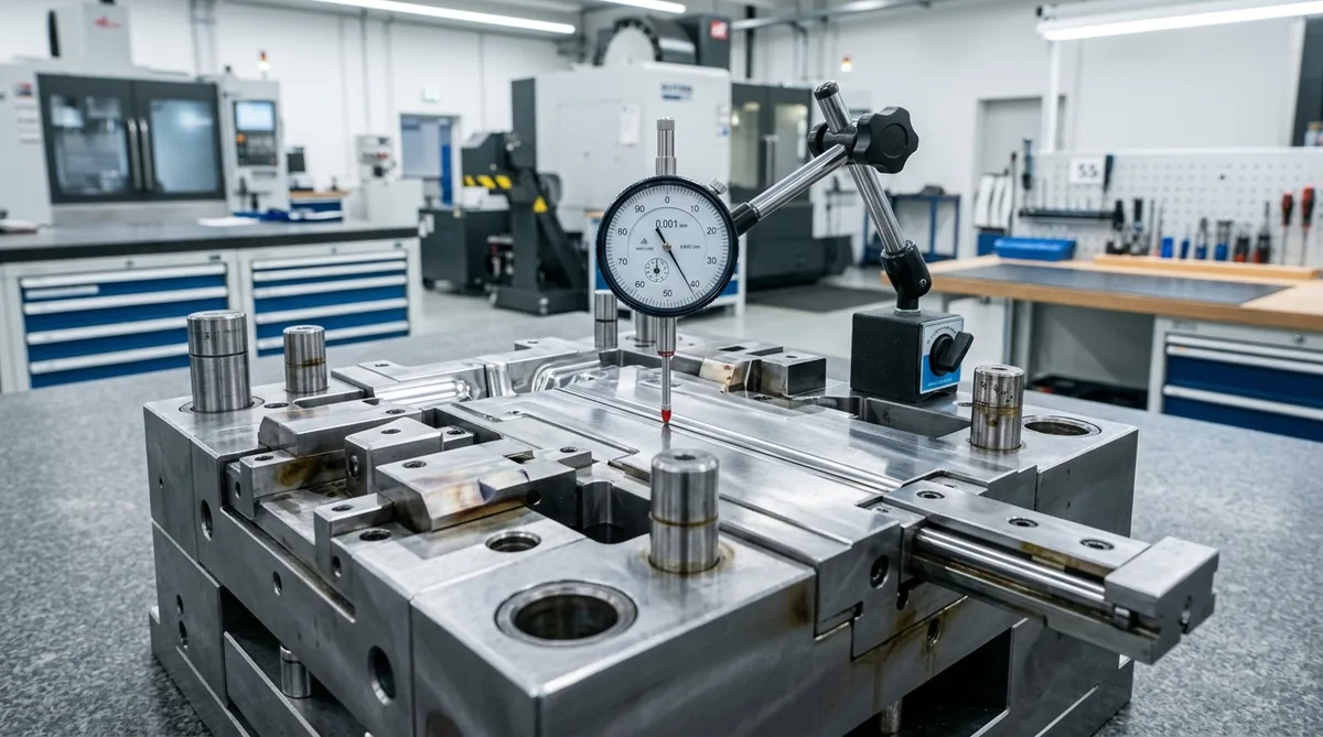
Engineering Defect Troubleshooting & Process Optimization Matrix
The following engineering matrix outlines root causes, tooling remedies, and scientific molding adjustments for resolving frequent plastic injection molding problems:
| Defect Category | Visual Symptom | Root Mechanism | Tooling Correction | Molding Process Fix |
|---|---|---|---|---|
| Sink Marks | Localized surface hollows at rib roots | Volumetric thermal contraction in thick walls | Thin ribs to 40%–50% wall; core out heavy sections | Increase packing pressure & holding time; lower melt temp |
| Flash | Thin plastic fins along parting lines | Clamping force exceeded; parting line gap > 0.02 mm | Spot/blue parting surfaces; verify shut-off preloads | Increase machine clamp tonnage; reduce injection peak pressure |
| Part Warpage | Bowing, twisting, or non-flat mating edges | Differential cooling and anisotropic resin shrinkage | Add conformal cooling circuits; optimize gate positions | Equalize cavity/core mold temps; extend cooling cycle |
| Weld Lines | Faint seam line where melt fronts converge | Sub-optimal melt fusion temperature & trapped air | Add perimeter venting inserts; relocate gate away from holes | Elevate injection speed & tool temperature |
| Short Shots | Incomplete mold filling at thin extremities | High flow resistance or air entrapment backpressure | Enlarge gate diameter and sub-runners; expand mold vents | Increase injection volume, stroke transfer point, and speed |
Resin Shrinkage, Venting & Tool Steel Selection Parameters
Achieving microscopic tool seal integrity requires matching specific tool steels and venting clearances to the selected thermoplastic:
| Polymer Resin | Volumetric Shrinkage (%) | Max Vent Depth (mm) | Recommended Tool Steel | Tool Hardness (HRC) |
|---|---|---|---|---|
| ABS (General Purpose) | 0.4 – 0.7 % | 0.025 – 0.035 mm | NAK80 / 718H | 38 – 42 HRC |
| Polycarbonate (PC) | 0.5 – 0.8 % | 0.030 – 0.045 mm | S136 Mirror Polish | 48 – 52 HRC |
| POM (Acetal / Delrin) | 1.8 – 2.5 % | 0.015 – 0.020 mm | S136 Stainless | 50 – 54 HRC |
| PA66 + 30% GF | 0.3 % (Flow) / 0.9 % (Trans) | 0.015 – 0.025 mm | H13 / SKD61 (Nitrided) | 52 – 56 HRC |
| PEEK (Unfilled) | 1.2 – 1.6 % | 0.012 – 0.018 mm | S136 High Heat Treated | 54 – 58 HRC |
DFM Rules to Prevent Injection Molding Deficiencies
- Maintain Constant Wall Thickness: Transition between walls must incorporate gradual tapers (less than or equal to 3:1 slope) rather than abrupt steps to prevent vortex air entrapment and localized sink.
- Incorporate Generous Draft Angles: Specify at least 1.0° to 1.5° draft per side on exterior walls, and 2.0° or greater on textured surfaces (such as VDI 3400 Ref 24+ or Mold-Tech finishes) to prevent drag marks and ejector pin punch-through.
- Optimize Gate Location and Type: Position edge or submarine gates into the heaviest cross-section of the part, allowing melt to flow from thick to thin areas without prematurely solidifying.
- Radiused Internal Corners: Apply internal fillet radii of at least 0.5 x nominal wall thickness (R >= 0.8 mm) to distribute hydraulic fill stress and avoid premature mold core erosion.
If external aesthetics cannot change, engineers can core out the rear of the heavy section with CNC-machined core pins, increase packing pressure during the second stage of injection, or switch to a lower-shrinkage resin or chemical foaming agent.
Parting line flash under high clamping forces typically stems from localized tool deflection, foreign debris or flash buildup on mating surfaces, non-parallel machine platens, or excessive peak injection speed causing dynamic mold separation before clamp lockup.
Glass-filled nylon experiences severe anisotropic shrinkage because the microscopic fibers align along the flow vectors. Shrinkage in the flow direction is minimal (approx. 0.3%), while transverse shrinkage is three times higher (approx. 0.9%), generating intense internal twisting stresses as the part cools.
Launch Your Custom Injection Mold Tooling Project
Partner with our experienced tooling engineers to eliminate sink marks, flash, and warpage before cutting steel. Upload your 3D CAD files (STEP / IGES) for an immediate DFM manufacturability analysis and competitive tooling quotation.