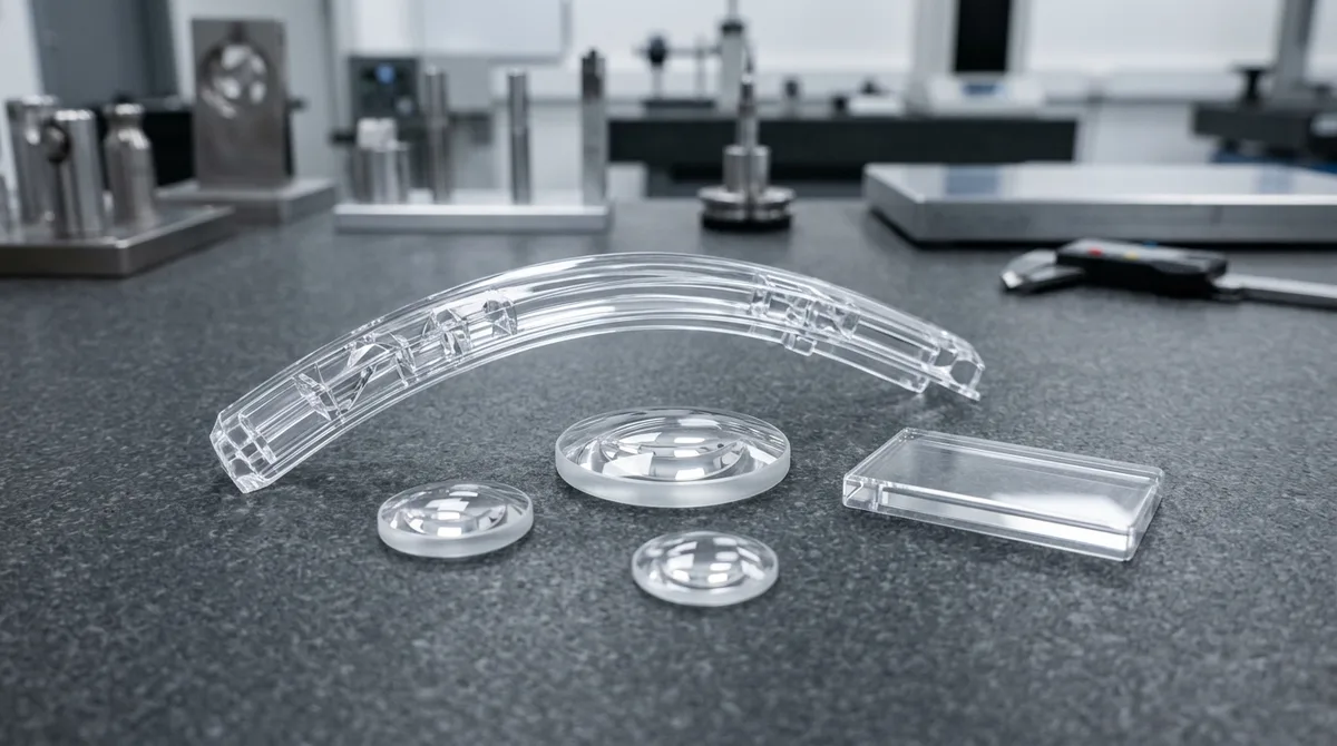
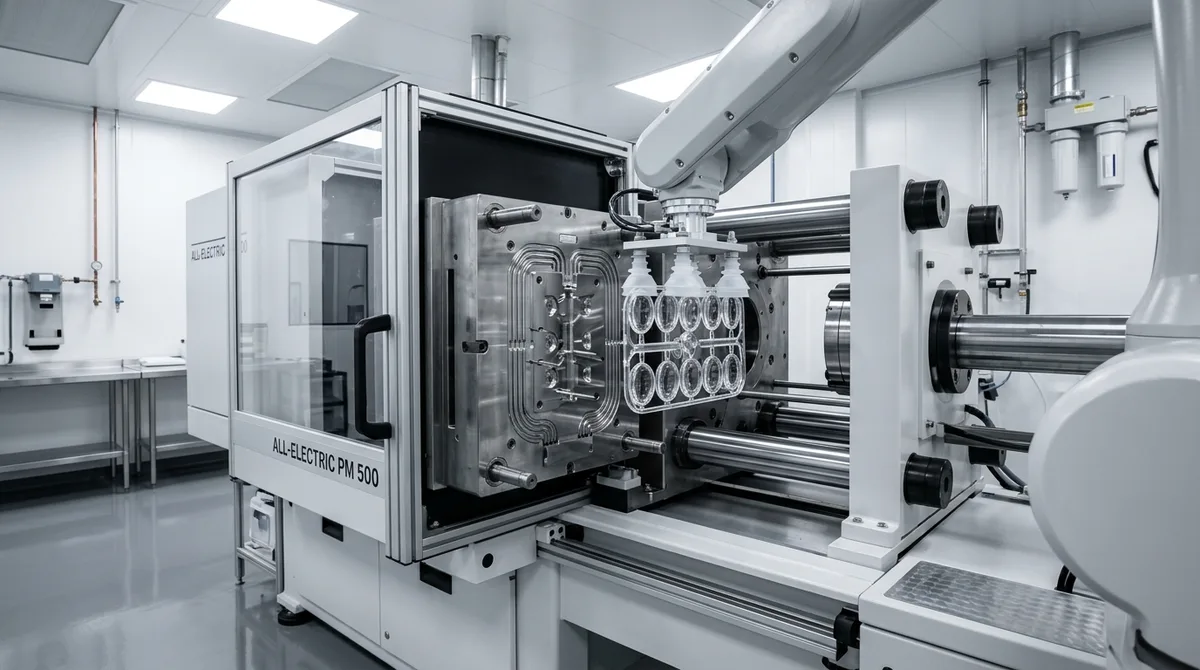
Achieving exceptional optical clarity in PMMA injection molding requires mastering polymer melt rheology, micro-precision toolmaking, and scientific mold cooling control. Polymethyl methacrylate (PMMA), widely known as acrylic, provides 92% luminous transmittance, exceptional UV resistance, and low optical dispersion, making it the premier material for precision camera optics, light pipes, and automotive lighting prototypes. At our specialized cleanroom facility, we operate all-electric molding presses and mirror-polished S136 stainless steel tooling to deliver high-yield custom injection molding service for demanding optoelectronic and medical sensor applications.
- Core Focus & DFM Scope: Actionable shop-floor engineering guidelines for PMMA injection molding, covering material selection, geometric tolerancing, and defect prevention.
- Dimensional Tolerance Baseline: General molded/cast features hold ISO 2768-mK or ±0.05 to ±0.10 mm (±0.002″ to ±0.004″); critical post-machined datum bores achieve ±0.010 mm (±0.0004″).
- Tooling & Surface Integrity: Cavity surfaces finished from SPI A-2 mirror polish (Ra 0.05 µm / 2 µin) to VDI 3400 spark-eroded textures with mandatory 1.0°–2.5° draft angle compensation.
- Metrology & Flow Validation: Pre-tooling DFM and rheological fill simulation paired with Zeiss CMM first-article inspection (FAI) and wall-thickness ultrasonic/section verification.
- Ex-Factory Turnaround: 7 to 12 business days for vacuum cast/urethane bridge batches; 18 to 35 business days for rapid aluminum/P20/H13 tooling and T1 sample delivery (excluding 3–5 days air transit).
The Optical Physics of PMMA: Why Acrylic Dominates Precision Optics
Unlike standard commodity resins, optical polymers must adhere to strict photonic benchmarks:
- Total Luminous Transmittance: Cast and molded optical PMMA transmits 92% of visible light across the 380–780 nm spectrum, matching high-purity crown glass (BK7) while weighing 50% less.
- Low Optical Dispersion (Abbe Number Vd = 58): High Abbe value ensures minimal chromatic aberration and color fringing in multi-element camera lenses, prisms, and collimators.
- Near-Zero Inherent Birefringence: PMMA exhibits extremely low photoelastic sensitivity (photoelastic constant C ≈ -4.3 × 10−¹² Pa−¹ compared to polycarbonate’s +82 × 10−¹² Pa−¹), preventing optical wave-front distortion and polarized rainbow fringe halos.
- Superior UV & Weathering Resistance: PMMA is inherently stable against ultraviolet degradation, retaining its clarity and high transmittance for over a decade in outdoor automotive environments without yellowing.
Tooling Architecture for Optical PMMA: Steel Selection and Mirror Polishing
Molding optical acrylic demands steel tooling engineered to withstand high injection pressures without microscopic surface defects:
- Premium ESR-Refined S136 Mold Steel: We construct cavity and core inserts from vacuum-degassed, Electro-Slag Remelted (ESR) S136 stainless steel heat-treated to 52–54 HRC. This homogeneous metallurgical microstructure eliminates non-metallic inclusions, micro-voids, and pitting that distort light refraction.
- SPI A-1 Diamond Mirror Polish: Cavity surfaces undergo multi-stage manual and ultrasonic lapping with graded diamond compounds progressing down to 0.5-micron paste, achieving an optical mirror finish with surface roughness Ra < 0.005 µm.
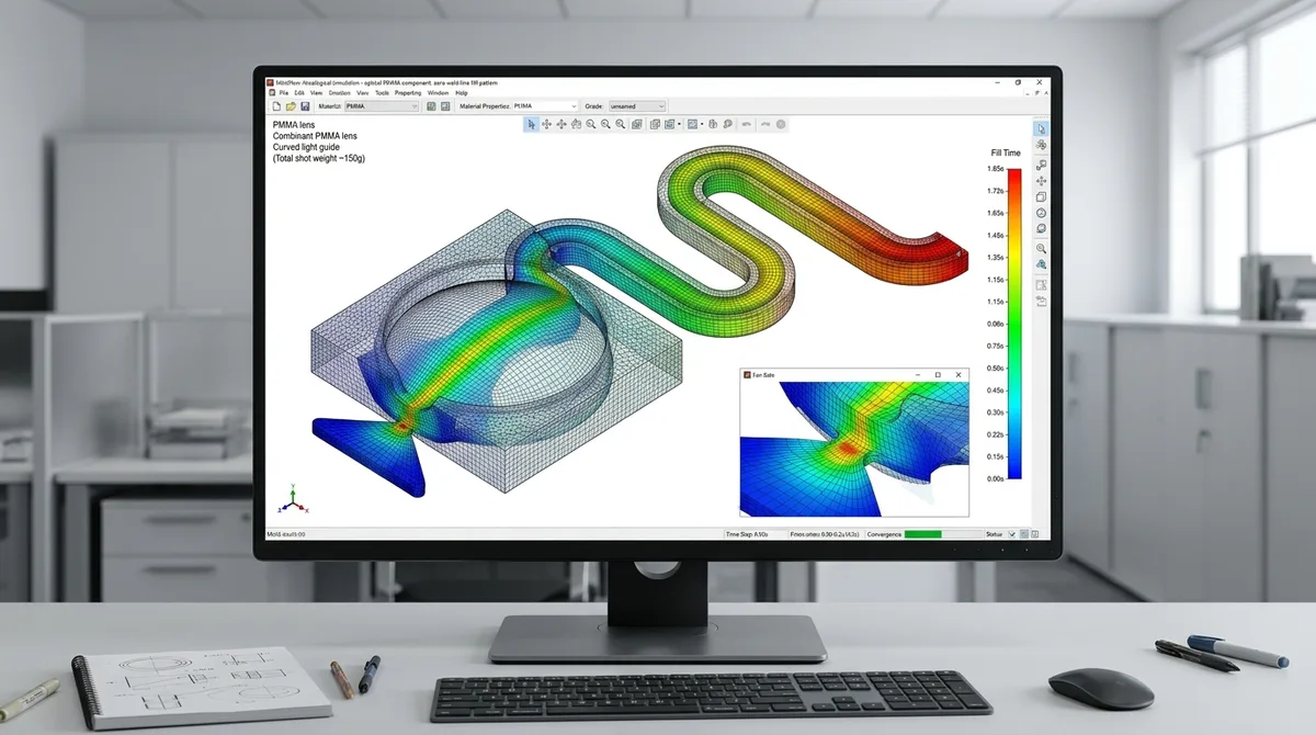
- Balanced Runner & Sub-Gate Architecture: Heavy edge gates or fan gates positioned at the thickest section ensure gradual cavity filling without jetting, melt fractures, or localized shear stress.
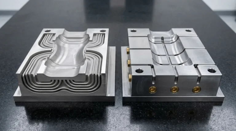
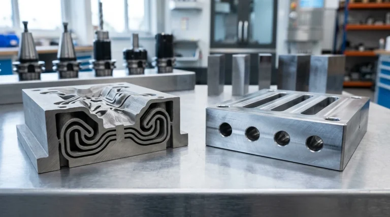
- Conformal Cooling Circuits: CNC-drilled and vacuum-brazed cooling channels maintain cavity surface temperature uniformity within ±1.0°C, eliminating non-uniform thermal shrinkage and frozen-in residual optical birefringence.
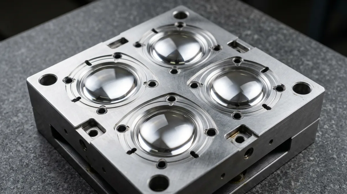
To ensure laminar polymer flow during injection, specialized gate geometry is verified prior to tool steel cutting. The gate must prevent velocity spikes that cause jetting (worm-like flow tracks) and localized shear degradation near the optical aperture.
Scientific Processing Parameters: Eliminating Silver Streaks and Internal Voids
Optical acrylic is hygroscopic and sensitive to thermal degradation. Producing zero-defect optical components requires rigorous scientific process adherence:
- Dehumidifying Desiccant Pre-Drying: PMMA pellets readily absorb ambient atmospheric moisture (0.3%–0.4%). Raw material must be dried in dehumidifying desiccant hopper dryers at 75°C–85°C with a dew point below −40°C for 4 to 6 hours to reduce moisture content strictly below 0.02%. Residual moisture vaporizes instantly inside the heated barrel, causing silver streak splay marks and internal micro-voids.
- Gentle Melt Plasticization: Low backpressure (50–80 bar) and moderate screw speeds (40–60 RPM) with low-shear optical screws prevent shear overheating and polymer chain degradation.
- Two-Stage Profiled Injection: Slow initial fill speeds prevent gate blush, accelerating across the main body before decelerating prior to cavity pack out to prevent parting line flashing.
- Extended Packing & Holding Dwell: Because PMMA has a relatively low thermal conductivity, high second-stage packing pressure (800–1200 bar) must be held until the gate completely freezes to compensate for volumetric shrinkage and prevent vacuum voids in thick optical cross-sections.
Optical Material Benchmark: PMMA vs. Polycarbonate (PC) vs. COP/COC
The following engineering matrix compares PMMA against common alternative optical polymers and optical crown glass:
| Optical Property | Optical PMMA (Acrylic) | Optical Polycarbonate (PC) | Cyclic Olefin (COP / COC) | Crown Glass (BK7) |
|---|---|---|---|---|
| Light Transmittance (%) | 92.0 % | 88.0 – 90.0 % | 92.0 % | 92.5 % |
| Refractive Index (nd) | 1.491 | 1.585 | 1.530 | 1.517 |
| Abbe Number (Dispersion) | 58 (Very Low Dispersion) | 30 (High Dispersion) | 56 (Low Dispersion) | 64 (Ultra-Low Dispersion) |
| Birefringence Level | Near-Zero | High (Stress Fringe Prone) | Extremely Low | Zero |
| Impact Resistance | Moderate (Brittle) | Exceptional (Shatterproof) | Moderate | Very Low (Fragile) |
| Material Cost Factor | Economical ($) | Moderate () | Premium () | High Tooling / Grind ($) |
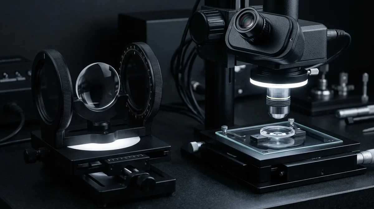
Because optical performance in sensor and vision systems is severely impaired by internal residual stresses, molded PMMA components are systematically validated using polariscope birefringence testing and non-contact optical metrology.
Scientific PMMA Molding Parameters & Control Windows
Strict process monitoring maintains optical and geometric compliance across production batches:
| Molding Parameter | Recommended Range | Critical Limit | Risk if Out of Spec |
|---|---|---|---|
| Melt Temperature | 215°C – 245°C | Max 260°C | Thermal degradation & yellowing |
| Mold Surface Temp | 65°C – 85°C | ±1.5°C across core/cavity | Part warpage & surface haze |
| Injection Pressure | 800 – 1,400 bar | 1,600 bar max | Parting line flash & residual stress |
| Drying Moisture Content | < 0.02 % | 0.04 % max | Silver streaking & internal voids |
| Linear Shrinkage Rate | 0.4 – 0.7 % | Grade specific | Dimensional non-compliance |
Post-Molding Thermal Annealing and Optical Coatings
To ensure long-term dimensional stability and prevent stress cracking in service:
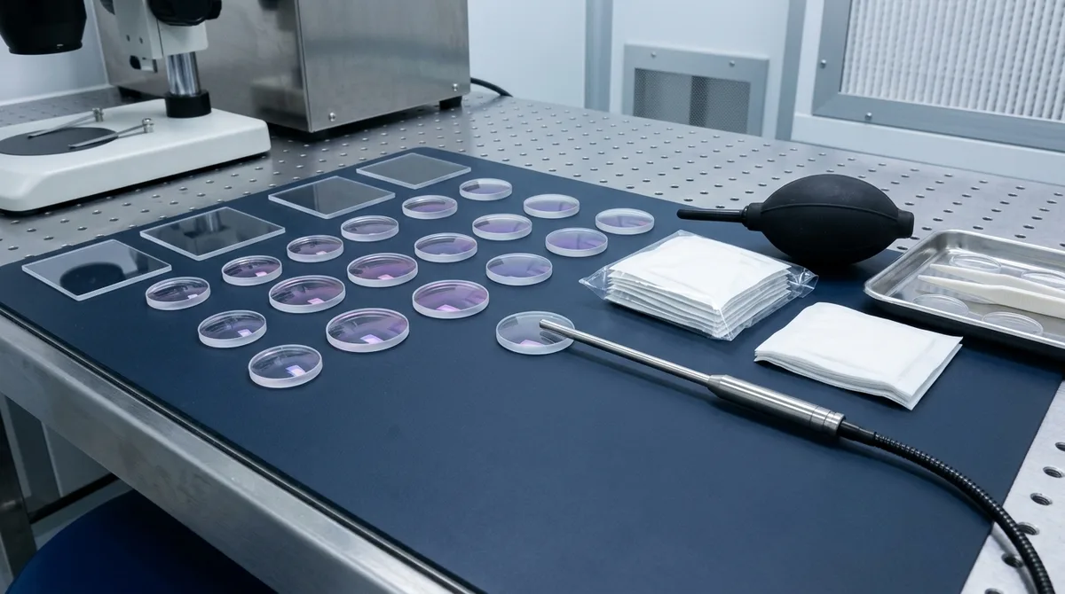
- Thermal Annealing: Precision PMMA optics are baked in recirculating hot-air ovens at 70°C–80°C (strictly below PMMA glass transition temperature Tg ≈ 105°C) for 2 to 4 hours, followed by slow cooling. This relieves locked-in frozen molecular shear stresses and eliminates delayed micro-crazing without part distortion.
- Anti-Scratch Hard Coating: Optical PMMA has an inherent surface pencil hardness of 2H–3H. Dip-coating or flow-coating with polysiloxane UV-curable hard coats increases surface hardness up to 5H–6H, dramatically improving abrasion and scratch resistance in automotive and consumer electronics.
- Anti-Reflective (AR) Coatings: Multi-layer dielectric AR thin-film coatings applied via vacuum sputtering boost visible light transmission from 92% to over 98% for premium LiDAR lenses and optical sensor windows.
Why Do Pmma Injection Molding Projects Experience Dimensional Warpage or Flash, and How Do You Prevent It?
Managing PMMA injection molding successfully requires balancing volumetric shrinkage, cavity clamping pressure, and thermal dissipation across uneven wall cross-sections. While uniform walls of 1.5 to 3.0 mm (0.060″ to 0.118″) stabilize flow fronts within ±0.05 mm (±0.002″), abrupt rib-to-wall transitions exceeding a 0.6:1 ratio induce localized sink marks, internal voids, and residual warpage.
Shop-Floor Quantitative Derivation: Clamping Force, Shrinkage & Thermal Cooling Balance
In our Shenzhen tooling and molding engineering practice, preventing parting-line flash and dimensional drift in PMMA injection molding starts with exact clamping tonnage and linear shrinkage compensation before steel or aluminum blocks are cut. Consider a structural housing with a projected cavity area Aproj = 140 cm² (21.7 in²) molded at an internal cavity pressure Pcav = 45 MPa (6,525 psi):
Fclamp = Aproj × Pcav × Sf = 140 cm² × 0.45 kN/cm² × 1.20 = 75.6 tonnes (83.3 US tons)
Simultaneously, tooling cavity dimensions (Dcavity) must compensate for isotropic or anisotropic material shrinkage (S). For a nominal 120.00 mm (4.7244″) datum spacing with a semi-crystalline or alloy shrinkage factor of S = 1.6% (0.016 mm/mm), the machined cavity steel dimension is calculated as Dcavity = Dnom × (1 + S) = 120.00 × 1.016 = 121.92 mm (4.8000″). To lock critical bearing bores or sealing faces within ±0.010 mm (±0.0004″), we leave a 0.40 mm (0.016″) stock allowance for post-molding 3-axis and 4-axis CNC finish milling.
Step-by-Step Shop-Floor Execution & Quality Protocol
To bridge CAD intent with repeatable shop-floor delivery, our engineering team enforces a four-stage execution workflow across every prototype and low-volume production batch:
- Step 1: Rheological Flow & Wall-Thickness DFM Audit: Analyze 3D CAD geometry (STEP/IGES) to verify uniform wall sections, apply 1.0° to 2.5° draft angles per VDI 3400 / SPI texture depth, and position gates away from cosmetic or high-stress zones.
- Step 2: Precision Cavity Machining & Venting Calibration: Machine P20, H13, S136, or 7075-T651 tooling inserts via high-speed CNC milling and Wire/Sinker EDM, grinding perimeter gas vents to 0.015–0.030 mm (0.0006″–0.0012″) depth to evacuate trapped air without flash.
- Step 3: Thermal Stabilization & Scientific Process Windowing: Stabilize mold tool temperature via turbulent conformal/baffle cooling channels (Reynolds number Re > 4,000) and decouple fill, pack, and hold stages to eliminate weld lines and internal porosity.
- Step 4: T1 First-Article Zeiss CMM & Section Verification: Inspect T1 shots after 24-hour thermal conditioning at 20°C (68°F) using Zeiss CMM probing and optical comparator overlays against ISO 2768-mK and drawing GD&T callouts.
Shop-Floor Defect Troubleshooting & Corrective Action Matrix
When evaluating part geometry during pre-production DFM review, our manufacturing engineers screen for the following failure modes and apply proven corrective controls:
| Defect / Symptom | Physical Root Cause | Shop-Floor Corrective Action | Recommended DFM Spec Limit |
|---|---|---|---|
| Parting-Line Flash / Burrs | Insufficient clamp tonnage, excessive injection velocity, or vent depth exceeding 0.04 mm (0.0016″) | Increase clamp safety factor to 1.25×, switch from velocity-to-pressure transfer at 98% fill, and lap parting faces to ≤0.010 mm (≤0.0004″) shutoff. | Flash ≤ 0.05 mm (0.002″) |
| Localized Sink Marks & Voids | Rib-to-wall thickness ratio exceeding 60% causing core thermal contraction after skin freeze | Coring out thick bosses, reducing rib root thickness to 50%–60% of nominal wall, and extending packing pressure until gate freeze-off. | Rib root = 0.5–0.6 × twall |
| Flow Weld / Knit Line Weakness | Converging melt/flow fronts cooling below fusion threshold around cored holes or inserts | Raise melt and mold surface temperatures by 15°C–25°C (27°F–45°F), add overflow wells at knit zones, and relocate gate entry vectors. | Tensile retention ≥ 85% |
| Post-Ejection Warpage & Twist | Differential cooling across asymmetric cavity halves or fiber orientation anisotropy | Balance core/cavity coolant delta within ΔT ≤ 5°C (9°F), anneal stressed parts in precision cooling jigs, and post-machine critical datums. | Flatness ≤ 0.10 mm / 100 mm |
Engineering Trade-Offs: When NOT to Over-Specify
When to Avoid This Process (Engineering Limitations): Do not specify dedicated hard tooling or molding workflows when unit quantities are under 10 pieces and the design geometry is still undergoing weekly functional revisions. In early-stage validation where upfront tooling amortization and 18 to 35 business days of tool fabrication delay testing, direct high-speed 3-axis and 4-axis CNC machining from solid engineering billet or polyurethane vacuum casting (4 to 12 business days ex-factory) delivers superior agility with zero steel modification risk.
🔗 Related Tooling & Molding Engineering Benchmarks:
Optimizing PMMA injection molding requires coordinating cavity thermal management, surface texture draft angles, and bridge production pathways. Explore our in-depth guides on Conformal Cooling vs. Conventional Cooling Channels to cut cycle times by 20%–35%, Preventing Flow Marks & Cosmetic Molding Defects, and Polyurethane Vacuum Casting for 10–50 Unit Bridge Runs.
Frequently Asked Questions
Silver streaks (splay marks) are primarily caused by moisture trapped within the resin pellets. Because PMMA is hygroscopic and absorbs up to 0.4% moisture from atmospheric humidity, it must be dried in a dehumidifying desiccant dryer at 75°C to 85°C (dew point ≤ −40°C) for 4 to 6 hours to achieve moisture levels strictly below 0.02% prior to plasticization.
PMMA offers higher optical clarity (92% vs 89%), a superior Abbe number (58 vs 30) with virtually zero color fringing, and natural UV stability without yellowing. In contrast, Polycarbonate provides far greater impact resistance, making PC preferable for forward-facing rock-strike headlamp lenses, while PMMA is standard for rear taillights, interior ambient light guides, and precision optical sensors.
Vacuum-degassed, ESR-refined S136 stainless steel heat-treated to 52–54 HRC is the global engineering standard. Its dense, inclusion-free microstructure allows multi-stage diamond paste polishing down to 0.5-micron grit, achieving an SPI A-1 mirror finish (Ra < 0.005 µm) that transfers crystal-clear optical surfaces directly onto molded parts.
No. Unlike polycarbonate, PMMA must never be exposed to solvent vapor polishing (such as dichloromethane or acetone). Solvents trigger rapid chemical crazing, localized swelling, and severe stress cracking in acrylic. In PMMA injection molding, optical surface quality is directly replicated from the mirror-polished SPI A-1 mold steel cavity, followed by controlled thermal annealing at 70°C–80°C to relieve internal stresses.
Manufacture Precision PMMA Optical Components
Leverage our cleanroom molding infrastructure, SPI A-1 mirror tooling, and optical metrology for your acrylic components. Submit your 3D CAD files (STEP / IGES) today for an instant DFM manufacturability analysis and tooling quote.