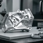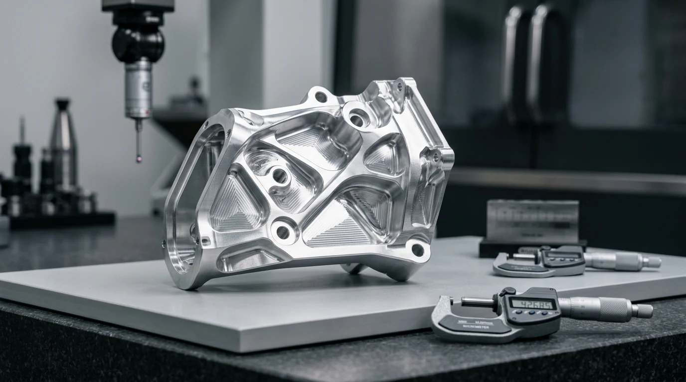
Across aerospace, medical robotics, performance automotive, and advanced energy systems, mechanical design paradigms have shifted radically. Driven by generative design, topology optimization, and weight-reduction imperatives, modern components are no longer simple assemblies of orthogonal plates and turned pins. Instead, engineers increasingly design monolithic, highly integrated structural nodes that consolidate dozens of discrete parts into single, complex workpieces.
While these organic structures deliver superior strength-to-weight ratios, eliminate mechanical fasteners, and prevent assembly vibration failure, they introduce formidable manufacturing challenges. Complex workpieces typically feature multi-sided undercut pockets, compound angled bearing bores, deep internal fluid galleries with high aspect ratios, and sub-10-micron geometric tolerancing (GD&T). When manufactured using conventional 3-axis CNC milling, these components require five to eight discrete machine setups, expensive custom soft-jaw fixturing, and suffer from cumulative datum stacking errors. This engineering guide examines how 5-axis CNC machining, feature-based CAM programming, Tool Center Point Control (TCPC), and in-process probing transform seemingly intractable complex workpieces into repeatable, cost-effective production runs.
1. The Anatomy of Modern Complex Workpieces: Engineering Challenges
A workpiece is classified as “complex” when its geometric envelope cannot be efficiently reached or cut within standard 3-axis Cartesian tool orientations. Common structural features include:
- Compound-Angled Bores and Flanges: Precision locating pin bores or fluid ports inclined at non-orthogonal spatial vectors relative to primary datums.
- Deep Pockets with High Length-to-Diameter (L/D) Ratios: Thin-walled pocket cavities where standard vertical end mills must extend beyond 5×D, causing severe tool deflection, chatter marks, and tool breakage.
- Undercuts and Re-entrant Geometries: Internal dovetails, O-ring seal grooves, and relief pockets shielded by overhang flanges that require specialized lollipop cutters or tilted spindle access.
- 3D Freeform Sculpted Surfaces: Aerodynamic turbine blisks, marine propeller impellers, and surgical implant geometries with continuous variable-radius curvatures.
The Conventional 3-Axis Dilemma: Setup Stacking Errors
Attempting to machine complex workpieces on standard 3-axis vertical machining centers (VMCs) initiates an escalating cascade of cost and quality risks:
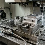
- Setup Stacking Error (ΣΔε): Every time a setup machinist unclamps a part to re-orient it in a new vice, positioning repeatability is compromised (±0.015 to ±0.030 mm per flip). When a critical true position or perpendicularity tolerance spans features cut in separate operations (Op10, Op20, Op30), tolerance budgets are completely consumed by fixturing variability.
- Custom Fixturing Overhead: Each unique part orientation demands custom CNC milled soft jaws, angle plates, or sine vices, adding thousands of dollars in non-recurring engineering (NRE) tooling and weeks of lead time.
- Extended Total Cycle Latency: Queuing workpieces across multiple machines and vice setups drastically inflates WIP (Work-in-Progress) inventory and scrap risk.
2. The 5-Axis CNC Solution: “Done-in-One” Architecture
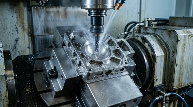
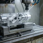
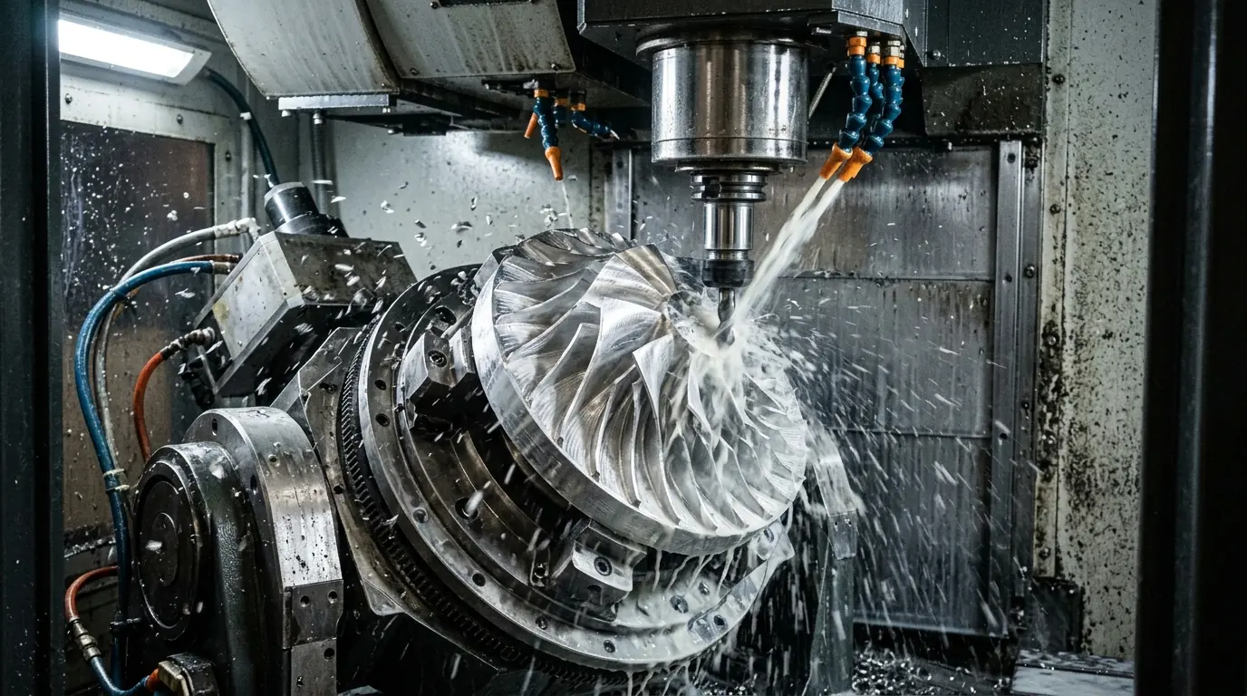
Five-axis CNC machine tools resolve the complex workpiece challenge by introducing two rotational axes (typically A and C, or B and C) alongside traditional X, Y, and Z linear axes. Machine kinematic architectures fall into three primary categories: trunnion table-table (tilting/rotary table), swivel head-table, and dual swivel head.
3+2 Positional Machining vs. Continuous 5-Axis Simultaneous Milling
Understanding when to deploy positional vs. continuous 5-axis toolpaths is a cornerstone of efficient process planning:
- 3+2 Positional Machining (Five-Sided Machining): The rotary axes (A/C or B/C) tilt and lock the workpiece at a specific compound spatial angle. The spindle then cuts using standard 3-axis linear motions. Because the rotary axes are mechanically clamped with high hydraulic holding torque, maximum machine rigidity is maintained. This allows aggressive roughing cuts with heavy chip loads while granting cutting tools orthogonal access to five sides of the part in a single setup.
- Simultaneous 5-Axis Continuous Milling: All five axes articulate concurrently in coordinated dynamic motion. This mode is mandatory for machining continuous 3D freeform contours (such as aero-engine impellers, spiral inducer screws, and turbine blisks) where the cutter orientation must continuously adjust normal to the evolving surface tangent vector.
The Mechanical Advantage: Short, Rigid Cutters
In conventional 3-axis milling of deep cavities, programmers are forced to utilize long-reach end mills (e.g., L/D = 6:1 or 8:1). According to cantilever beam deflection theory:
Deflection (δ) ∝ (F × L3) / (3 × E × I)
Tool deflection increases with the cube of cutter overhang length (L3). Doubling tool length results in an eight-fold increase in deflection and chatter vibration! By tilting the workpiece or spindle head in 5-axis machining, the cutting tool can access deep cavity sidewalls using ultra-short, stubby end mills (L/D ≤ 2.5:1). This eliminates vibration, extends carbide tool life by up to 300%, and delivers mirror-smooth surface finishes down to Ra 0.4 μm without hand polishing.
3. Tool Center Point Control (TCPC / RTCP) Mechanics
In traditional 3-axis CNC machining, the programmed path matches the physical machine coordinates directly. However, when a workpiece rotates on a trunnion table, the physical position of a part feature shifts radically in X, Y, and Z space as the rotary angle changes.
Modern high-performance CNC controllers (Heidenhain TNC, Siemens 840D, Fanuc 31i-B5) incorporate advanced dynamic kinematics known as Tool Center Point Control (TCPC) or Rotation Around Tool Center Point (RTCP) (e.g., G43.4 in Fanuc, M128 in Heidenhain, TRAORI in Siemens):
- Dynamic Offset Calculation: The controller continuously tracks the precise spatial center point of the cutter tip relative to the part coordinate system in real time, automatically compensating for rotary pivot arm lengths and table angular displacements.
- Feedrate Normalization: Because linear tool feed rates across rotating surfaces vary dramatically depending on the distance from the rotary center, TCPC automatically recalibrates axis servo velocities to maintain constant chip load and uniform surface texture.
- Setup Position Independence: Workpieces do not need to be positioned at the exact physical center of the rotary table; the controller reads the active Work Coordinate System (WCS) and dynamically compensates for part eccentricity.
4. Feature-Based CAM Automation & Standardized Machining Databases
As workpieces grow in complexity, CAM programming can become a labor bottleneck. Modern digital machine shops eliminate manual toolpath programming through Feature-Based Machining (FBM) and centralized technical databases:
1. Automated Feature Recognition (AFR)
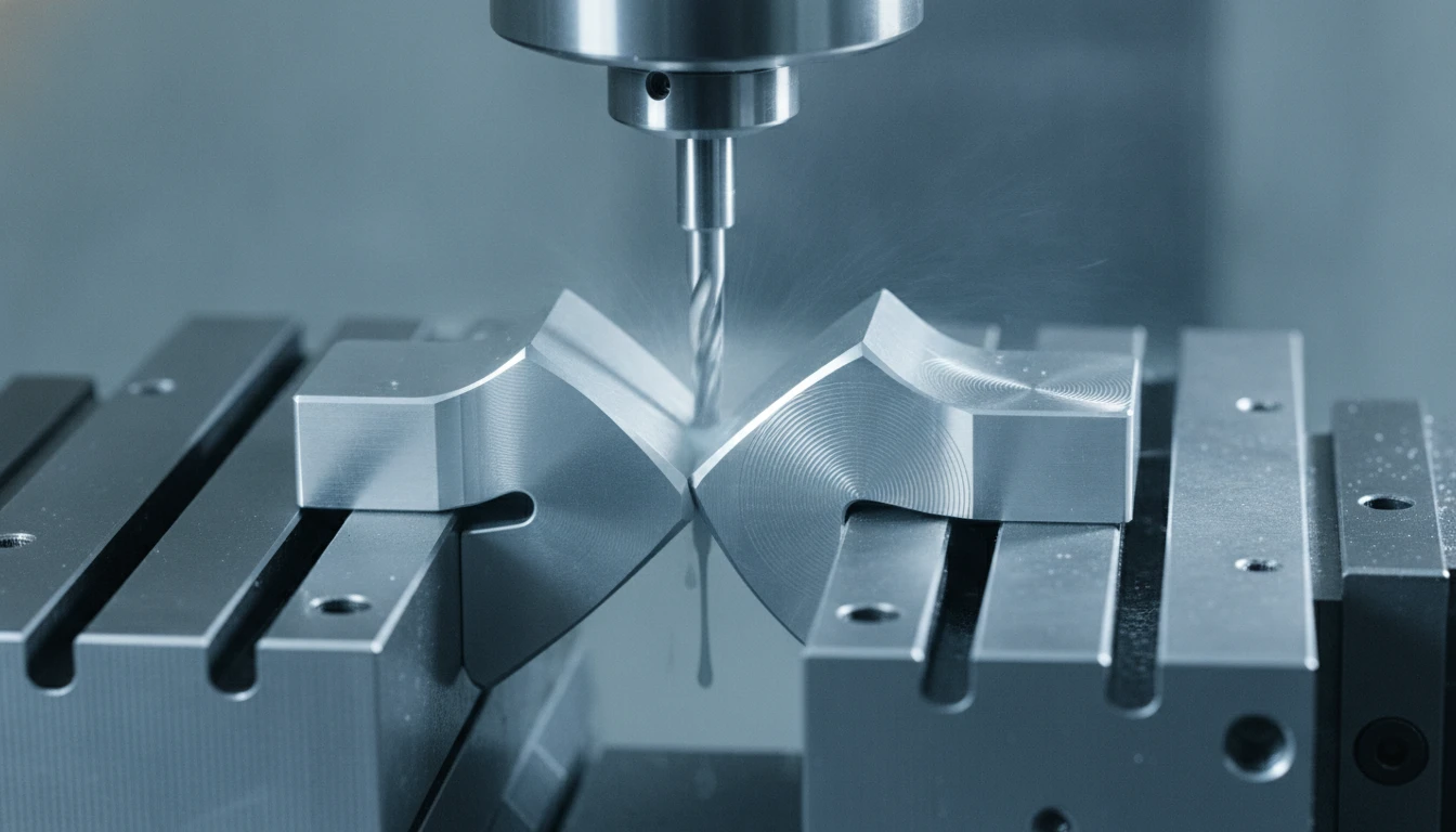
Rather than manually selecting individual surfaces, CAM algorithms scan imported solid models to identify recognized engineering topologies—including stepped bores, compound-angled tapped holes, open pockets, blind slots, and chamfers. Standardized cutting operations are automatically associated with each detected feature.
2. Standardized Process Rule Libraries
At AS Prototypes, our engineering team curates validated process templates for recurring structural features across various alloys (6061-T6, 7075-T6, Ti-6Al-4V, 17-4PH, Inconel 718):
- Hole Strategy Automation: Spot drill → High-penetration coolant-through carbide drill → Helical circular interpolation finish → Thread mill.
- Trochoidal Dynamic Pocketing: Maintaining constant cutter engagement angle (θ ≈ 35°) with high axial depth of cut (Ap up to 2×D) and low radial stepover (Ae 8–15%), tripling material removal rates (MRR).
- Master Tooling Standardization: Machines are configured with permanent 40- to 60-tool master carousels, eliminating setup teardowns between diverse customer projects.
3. Digital Twin Kinematic Simulation & Collision Avoidance
Machining complex 5-axis parts carries substantial machine collision risks between the high-speed spindle housing, toolholders, trunnion table, and vice fixtures. Before G-code reaches the shop floor, comprehensive Digital Twin simulations (such as VERICUT or integrated Siemens NX machine simulation) verify axis limits, identify singular point anomalies, and ensure complete collision immunity.
5. Comprehensive Engineering Comparison: Machining Strategies for Complex Parts
The following technical matrix compares the operational trade-offs of various machining strategies when tackling complex multi-sided workpieces:
| Machining Methodology | Required Setups | Fixturing Complexity | Cumulative Datum Error | Cutter Stick-Out (L/D) | Achievable Surface Finish | Best-Fit Workpiece Geometries |
|---|---|---|---|---|---|---|
| Traditional 3-Axis Multi-Setup | 4 to 8 Operations | High (Custom soft jaws, sine plates) | ±0.030 to ±0.060 mm (Stacked) | Long (6:1 to 10:1) | Ra 1.6 – 3.2 μm (Chatter risk) | Simple prismatic plates, 2.5D brackets with coplanar features |
| 3+2 Positional 5-Axis Milling | 1 to 2 Setups (“Done-in-One”) | Low (Standard zero-point / dovetail) | ±0.005 to ±0.012 mm | Short & Rigid (≤ 2.5:1) | Ra 0.8 – 1.6 μm | Multi-sided transmission housings, angled hydraulic manifolds, medical chassis |
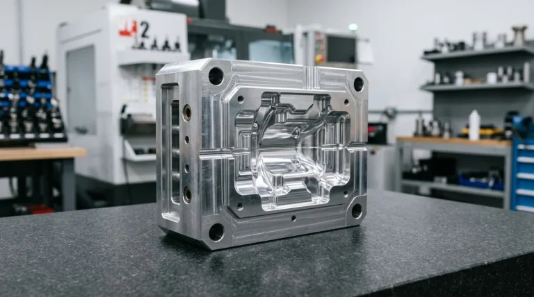
| Continuous Simultaneous 5-Axis | 1 Setup (Single Clamping) | Low (Pneumatic chuck / expanding arbor) | ±0.005 to ±0.010 mm | Optimized Vector Reach | Ra 0.4 – 0.8 μm | Turbine blisks, aerospace impellers, organic prosthetic joints, complex mold cores |
| Multi-Tasking Mill-Turn Center | 1 Setup (Main & Sub-Spindle Handover) | Minimal (Collet chucks & pie jaws) | ±0.003 to ±0.008 mm | Short & Rigid | Ra 0.4 – 0.8 μm | Rotational shafts with off-center cross-holes, eccentric cams, aerospace spool valves |
| Wire EDM Assisted Profiling | Complementary Setup | Simple clamping rails | ±0.002 to ±0.005 mm | N/A (Non-contact wire) | Ra 0.2 – 0.4 μm (Mirror finish) | Sharp internal square corners, micro-slits (<0.2 mm), high-aspect internal splines |
6. In-Process Metrology & Closed-Loop Quality Assurance
Machining complex parts is incomplete without rigorous in-process verification. At AS Prototypes, we integrate automated probing into machining cycles:
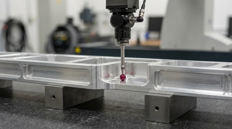
- Spindle-Mounted Optical Probes: High-precision wireless probing systems (such as Renishaw OMP60) automatically locate raw billet stock datums, verify part seating against fixture locating pins, and dynamically update G54 work coordinate offsets prior to cutting.
- In-Process Dimensional Inspection: After semi-finishing passes, the spindle probe automatically measures critical internal bore diameters and web thicknesses while the part remains clamped. If thermal drift or cutter wear has occurred, the CNC controller automatically recalculates tool wear offsets and applies a spring finishing pass.
- On-Machine Verification (OMV): Complex freeform surface profiles are checked on-machine against the CAD model before un-clamping, guaranteeing that out-of-spec workpieces never reach downstream assembly.
Frequently Asked Questions
Continuous 5-axis allows dynamic simultaneous tool reorientation during cutting, essential for aerodynamic impellers, blisks, and deep undercuts. 3+2 positional locks tilt axes, delivering higher dynamic rigidity for prismatic compound-angle faces.
TCPC automatically adjusts machine linear axes (X, Y, Z) in real-time as rotational axes (A, B, C) pivot, ensuring the actual cutting contact point precisely follows programmed coordinates regardless of pivot offsets.
We employ dynamic trochoidal clearing with constant radial engagement (8%–15% Ae), tapered shank carbide tooling with hydraulic or shrink-fit holders, and optimized tool tilting to utilize shorter, stiffer end mills.
Simplify Your Complex Workpieces with AS Prototypes
Don’t let intricate geometries, multi-sided undercuts, and tight GD&T tolerances stall your product realization pipeline. AS Prototypes operates a cutting-edge fleet of simultaneous 5-axis CNC machining centers, high-speed mill-turn machines, and climate-controlled CMM metrology laboratories to deliver complex aerospace, robotic, and medical parts with zero compromise.
Our senior CAM programming engineers review every CAD model for DFM optimization, tool clearance, and cycle-time reduction prior to spindle start.