In precision mechanical design, specifying GD&T straightness (—) is essential for controlling the longitudinal linearity of hydraulic piston rods, linear guideways, ball-screw shafts, and precision dowel pins. Standard plus-or-minus (±) size tolerances only govern local two-point cross-sectional diameters and cannot prevent a slender shaft from bowing and binding inside mating bearings.
To eliminate geometric ambiguity, engineering drawings apply GD&T straightness (—) per ASME Y14.5-2018 and ISO 1101. Depending on Feature Control Frame (FCF) placement, straightness operates as Surface Line-Element Straightness (2D generator lines obeying Rule #1) or Derived Median Line (Axis) Straightness (⌀), overriding Rule #1 and permitting Maximum Material Condition (Ⓜ) bonus tolerance.
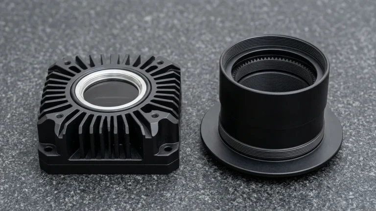
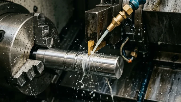
At our in-house CNC manufacturing facility, we produce slender shafts and guideways via precision CNC turning, Star Swiss-type lathes, and between-centers cylindrical grinding. Pairing thermal stress-relief annealing with high-speed 3-axis and 4-axis CNC milling and Zeiss CMM metrology, we hold straightness down to 0.005 to 0.010 mm per 100 mm (0.0002″–0.0004″).
Executive Summary & Engineering Takeaways (BLUF)
- Surface vs. Axis Callout Modes: Directing the leader arrow to a surface (
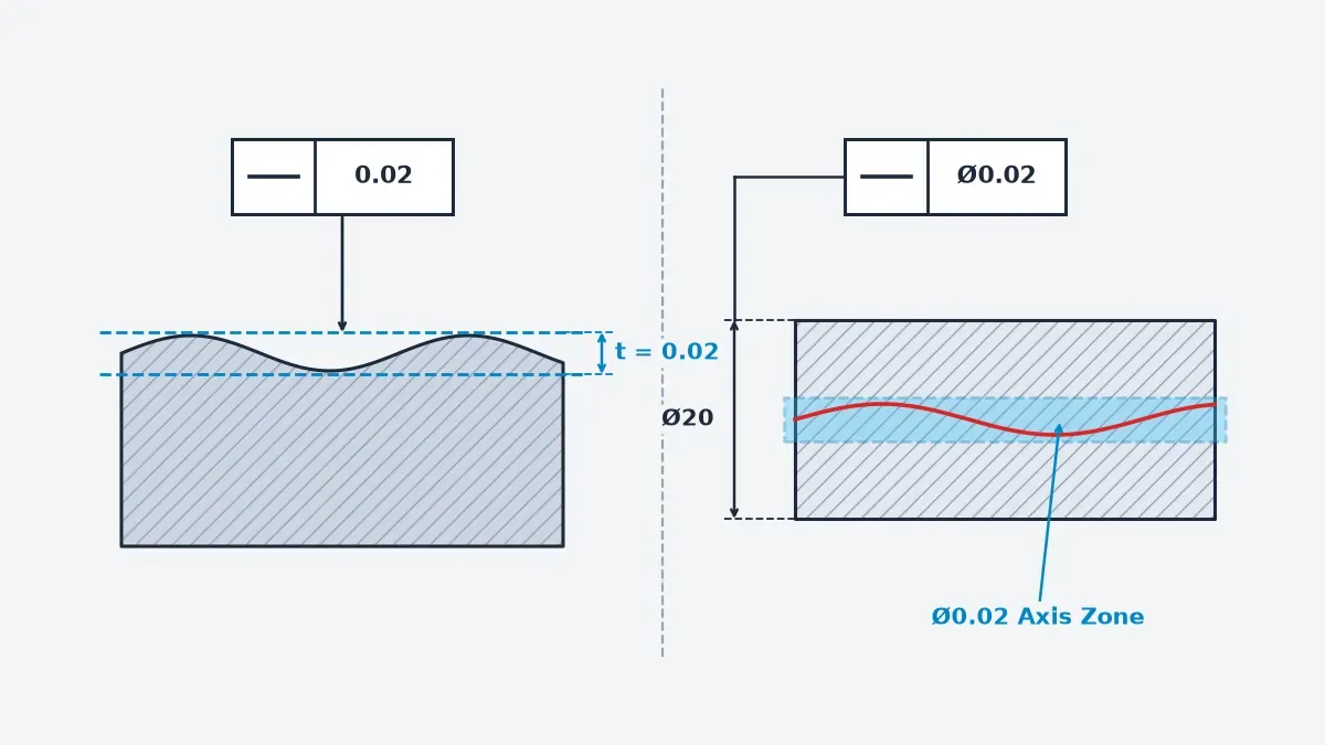
— 0.02) controls 2D generator lines under ASME Y14.5 Rule #1; attaching the frame to a diameter dimension (— ⌀0.02) creates a 3D cylindrical zone around the Derived Median Line (axis) and overrides Rule #1. - MMC Bonus & Functional Ring Gauging: Specifying
— ⌀0.02 Ⓜon a⌀20.00 ± 0.05 mmshaft fixes the outer Virtual Condition (VCshaft = dMMC + tgeo = ⌀20.07 mm), granting⌀0.12 mmstraightness at LMC (19.95 mm) and enabling rapid acceptance with a⌀20.07 mmFunctional GO Ring Gauge. - Deflection & Stress-Relief Physics: Supporting a slender shaft between centers reduces mid-span radial tool deflection 16-fold compared to cantilever chucking (
δ = Fr·L3 / 48·E·I), while alloy-specific thermal stress-relief annealing prevents post-machining bow. - Process Capability Tiers: Unnoted straightness follows ISO 2768-mK (ISO 2768-2 Table 1 Class K:
0.05–0.20 mmup to100 mm), tailstock CNC turning holds 0.010 to 0.025 mm per 100 mm (0.0004″–0.0010″), and Swiss turning or cylindrical/surface grinding holds 0.005 to 0.010 mm per 100 mm (0.0002″–0.0004″). - Ex-Factory Turnaround: DFM quotes within 24 hours, CNC turned/milled prototypes in 4 to 8 business days, and stress-relieved ground shafts in 7 to 12 business days (Ex-Factory Production & Inspection Turnaround, plus 3 to 5 business days air transit).
Article Engineering Navigation
- 1. What Is the Difference Between Surface Line-Element and Axis Straightness?
- 2. How Do ASME Y14.5 Rule #1, MMC (Ⓜ) Bonus & Virtual Condition Work?
- 3. Why Do Slender Shafts Bow? Cutting Deflection & Residual Stress
- 4. How Do Swiss Turning and Cylindrical Grinding Hold Tight Straightness?
- 5. How Is GD&T Straightness Verified with Zeiss CMMs, V-Blocks & Gauges?
- 6. What DFM Guidelines & Coating Rules Prevent Straightness Defects?
- 7. Technical Engineering FAQ
1. What Is the Difference Between Surface Line-Element and Axis Straightness?
In both ASME Y14.5-2018 and ISO 1101, the straightness symbol (—) is an unconditional form control that never references a datum feature. However, its geometric meaning changes fundamentally depending on whether the Feature Control Frame points to a surface profile or attaches to a size dimension.
When the leader arrow points to a surface or its extension line (— 0.02), it governs Surface Line-Element Straightness. The tolerance zone consists of two parallel lines spaced 0.02 mm (0.0008″) apart within a single 2D cutting plane parallel to the drawing view, with no ⌀, ±, or Ⓜ allowed.
On cylindrical shafts, surface straightness constrains longitudinal generator lines against waisting, barrel taper, or local concavities while strictly obeying ASME Y14.5 Rule #1 (Envelope Principle). On prismatic guideways, designers can apply different surface straightness tolerances along the longitudinal travel axis (— 0.01) versus the narrower transverse width (— 0.03).
Conversely, attaching the Feature Control Frame directly to the diameter dimension (— ⌀0.02 or — ⌀0.02 Ⓜ) specifies Derived Median Line (Axis) Straightness. As shown in the ASME Y14.5 comparison schematic below, this creates a 3D cylindrical zone (⌀0.02 mm / ⌀0.0008″) governing 3D shaft camber while overriding Rule #1.
| Engineering Parameter | Surface Line-Element (— 0.02) | Derived Median Line / Axis (— ⌀0.02 Ⓜ) | Recommended Application / When to Choose |
|---|---|---|---|
| Drawing Callout Syntax | Leader directed to surface or extension line (never use ± or ⌀). | Attached directly beneath or beside diameter dimension with ⌀ prefix. | Use surface mode for sealing lands; use axis mode for long shafts in bores. |
| Tolerance Zone Geometry | 2D Parallel Lines spaced 0.02 mm (0.0008″) apart in one cutting plane. | 3D Cylindrical Zone of ⌀0.02 mm (⌀0.0008″) enclosing cross-section centroids. | Use 2D zone for planar guideways; use 3D ⌀ zone for multi-directional rod bow. |
| ASME Y14.5 Rule #1 Interaction | Obeys Rule #1: Perfect form at MMC boundary (dMMC) remains enforced. | Overrides Rule #1: Outer boundary expands to Virtual Condition (VC = dMMC + tgeo). | Choose axis mode on slender rods (L/D > 8) where Rule #1 is too restrictive. |
| Material Condition Modifiers | Strictly RFS (Regardless of Feature Size); Ⓜ and Ⓛ are illegal. | RFS by default; explicitly permits MMC (Ⓜ) or LMC (Ⓛ) bonus tolerance. | Specify Ⓜ on static clearance pins and guide shafts to lower grinding cost. |
| Shop-Floor Metrology Method | Zeiss CMM linear stylus scan along each generator line on a granite plate. | Zeiss CMM multi-slice centroid fitting (RFS) or Functional GO Ring Gauge (Ⓜ). | Use Functional GO Ring Gauge at Ⓜ for 100% high-speed batch verification. |
2. How Do ASME Y14.5 Rule #1, MMC (Ⓜ) Bonus & Virtual Condition Work?
Under ASME Y14.5 Rule #1 (Envelope Principle), a cylindrical shaft dimensioned at ⌀20.00 ± 0.05 mm (⌀0.7874″ ± 0.0020″) without a feature-of-size straightness callout must exhibit perfect straightness (0.000 mm axial bow) whenever its local diameter sits at Maximum Material Condition (dMMC = 20.05 mm).
On slender shafts with length-to-diameter ratios above L/D = 8:1, enforcing zero bow at MMC causes unnecessary scrap. Attaching a Derived Median Line callout (— ⌀0.02 or — ⌀0.02 Ⓜ) explicitly overrides Rule #1, allowing controlled axial bow beyond the 20.05 mm size envelope while local two-point diameters stay within 19.95–20.05 mm.
Adding the Maximum Material Condition (Ⓜ) modifier establishes a constant worst-case mating boundary called the Virtual Condition (VC). For an external shaft, VCshaft = dMMC + tgeo; for an internal mating bore, VCbore = DMMC − tgeo. As actual shaft diameter departs from MMC toward LMC, every micrometer of diametral clearance converts 1:1 into bonus straightness tolerance.
📐 Worked Calculation: External Shaft & Mating Bore MMC (Ⓜ) Virtual Condition
Governing Equations: Bonusshaft = dMMC − dactual | ttotal = tgeo + Bonus | VCshaft = dMMC + tgeo | VCbore = DMMC − tgeo
Assembly Pair: Hardened 17-4PH piston shaft at ⌀20.00 ± 0.05 mm (dMMC = 20.05 mm, dLMC = 19.95 mm) with — ⌀0.02 Ⓜ mating inside a bronze gland bore at ⌀20.10 ± 0.02 mm (DMMC = 20.08 mm, DLMC = 20.12 mm) with — ⌀0.01 Ⓜ:
- External Shaft Virtual Condition:
VCshaft = 20.05 + 0.02 = ⌀20.07 mm (⌀0.7902″)(verifiable via a full-length⌀20.07 mmFunctional GO Ring Gauge). - Internal Bore Virtual Condition:
VCbore = 20.08 − 0.01 = ⌀20.07 mm (⌀0.7902″)(verifiable via a full-length⌀20.07 mmFunctional GO Plug Gauge;VCshaft ≤ VCboreguarantees 100% non-binding assembly). - Shaft at Nominal (
dactual = 20.00 mm):Bonus = 20.05 − 20.00 = 0.05 mm, givingttotal = 0.02 + 0.05 = ⌀0.07 mm (⌀0.0028″)permissible axis bow. - Shaft at LMC (
dactual = 19.95 mm):Bonus = 20.05 − 19.95 = 0.10 mm, givingttotal = 0.02 + 0.10 = ⌀0.12 mm (⌀0.0047″)permissible axis bow. - Tight-Size / Looser-Form Equivalent (
⌀20.00 ± 0.02 mm,dMMC = 20.02 mmwith— ⌀0.05 Ⓜ):VCshaft = 20.02 + 0.05 = ⌀20.07 mm; atdactual = 19.98 mm,ttotal = 0.05 + (20.02 − 19.98) = ⌀0.09 mm. - ISO h7 Bearing Shaft Benchmark (
⌀16.000 +0.000/−0.018 mmwith— ⌀0.020 Ⓜ):dVC = dMMC + tMMC = 16.000 + 0.020 = ⌀16.020 mm; atdactual = 15.984 mm, bonus tolerance yieldstallow = 0.020 + (16.000 − 15.984) = ⌀0.036 mm.
Actual Two-Point Shaft OD (dactual) | Feature Size State | RFS Straightness Zone (— ⌀0.02) | MMC Bonus (dMMC − dactual) | MMC Total Axis Zone (ttotal) | Functional GO Ring Gauge (VCshaft) |
|---|---|---|---|---|---|
20.05 mm (0.7894″) | MMC (Largest Shaft) | ⌀0.02 mm (⌀0.0008″) | 0.00 mm (0.0000″) | ⌀0.02 mm (⌀0.0008″) | ⌀20.07 mm (⌀0.7902″) |
20.03 mm (0.7886″) | Upper Intermediate | ⌀0.02 mm (⌀0.0008″) | 0.02 mm (0.0008″) | ⌀0.04 mm (⌀0.0016″) | ⌀20.07 mm (⌀0.7902″) |
20.00 mm (0.7874″) | Nominal Mean Size | ⌀0.02 mm (⌀0.0008″) | 0.05 mm (0.0020″) | ⌀0.07 mm (⌀0.0028″) | ⌀20.07 mm (⌀0.7902″) |
19.97 mm (0.7862″) | Lower Intermediate | ⌀0.02 mm (⌀0.0008″) | 0.08 mm (0.0031″) | ⌀0.10 mm (⌀0.0039″) | ⌀20.07 mm (⌀0.7902″) |
19.95 mm (0.7854″) | LMC (Smallest Shaft) | ⌀0.02 mm (⌀0.0008″) | 0.10 mm (0.0039″) | ⌀0.12 mm (⌀0.0047″) | ⌀20.07 mm (⌀0.7902″) |
3. Why Do Slender Shafts Bow? Cutting Deflection & Residual Stress
Achieving tight straightness on slender shafts requires controlling two physical failure mechanisms: elastic beam deflection under radial cutting thrust (Fr) and internal residual stress relaxation. Once shaft slenderness exceeds L/D > 8:1, radial compliance rises with the cube of overhang length (L3) and inversely with the fourth power of diameter (I = π·D4 / 64).
In an un-supported cantilever lathe setup, radial tool pressure pushes the free end away from the insert by δcantilever = (Fr·L3) / (3·E·I), producing severe bell-mouth taper. Engaging a hydraulic tailstock live center converts the workpiece into a supported span, cutting mid-span deflection 16-fold to δsupported = (Fr·L3) / (48·E·I).
📐 Worked Calculation: Cantilever vs. Between-Centers & Swiss Lathe Deflection
Equations: I = π·D4 / 64 | δcantilever = (Fr·L3) / (3·E·I) | δsupported = (Fr·L3) / (48·E·I) = δcantilever / 16
Example: Turning a ⌀16.0 mm × 160 mm (L/D = 10:1) 4140 / 17-4PH steel shaft (E = 200 GPa = 200,000 N/mm2, I = 1,024π ≈ 3,217 mm4) under radial thrust Fr = 150 N (33.7 lbf):
- Cantilever Chucking (Un-supported Free End):
δcantilever = (150 × 1603) / (3 × 200,000 × 3,217) = 0.318 mm (0.0125″)severe taper/bow. - Between Centers / Chuck + Live Center (16× Stiffer):
δsupported = 0.318 / 16 = 0.020 mm (0.0008″)mid-span deflection. - Swiss-Type Guide Bushing (
L = 3.0 mmOverhang):δSwiss = (150 × 3.03) / (3 × 6.434×108) ≈ 0.000002 mm (0.002 µm)(eliminates cantilever deflection). - Slender Shaft Benchmark (
d = 12.0 mm,L = 240 mm,E = 200 GPa,I = π·d4/64 = 1,017.88 mm4): Between-centers mid-span barrel camber isδmax = 0.0255 mm (25.5 µm)atFr = 18 Nfinish radial thrust (and0.255 mmatFr = 180 Nroughing thrust), versus0.000002 mmin a Swiss guide bushing.
Even with zero tool deflection, cold-drawn 4140, 304/316L, and 17-4PH bar stock carries high tensile skin stresses from mill drawing. Machining an asymmetric keyway or stepping down the outer diameter unbalances these locked-in stresses, causing the shaft or linear rail to bow immediately upon unclamping.
To prevent thermal warpage, our in-house heat-treatment protocol matches the exact alloy metallurgy: rough-turned 4140-QT and 304/316L shafts undergo sub-critical stress relief at 550–600°C; 17-4PH shafts are rough-turned with 0.25–0.35 mm radial grinding stock, vacuum precipitation-aged (480°C for Condition H900 or 550°C for H1025), and finish-ground between centers.
For hardened 440C bearing shafts (58–60 HRC), we integrate a -75°C sub-zero cryogenic soak between vacuum quenching and double tempering (160–190°C) to transform retained austenite before grinding. For milled aluminum guideways, 6061-T6 is stress-relieved at 150–165°C (302–329°F), whereas 7075-T651 relaxation is strictly capped at ≤ 100–110°C (212–230°F) to prevent over-aging softening.
4. How Do Swiss Turning and Cylindrical Grinding Hold Tight Straightness?
In our in-house machine shop, unnoted straightness defaults to ISO 2768-mK (ISO 2768-2 Table 1 Class K). Standard 3-jaw chuck turning holds 0.015–0.030 mm per 100 mm (0.0006″–0.0012″) on stub shafts (L/D ≤ 4:1), while tailstock support holds 0.010–0.025 mm per 100 mm (0.0004″–0.0010″) using high-entering-angle inserts (κr = 93°–95°, rε = 0.2 mm).
For slender shafts and pins (⌀1.0 to ⌀32.0 mm, L/D = 4:1 to 15:1), our Star Swiss-type sliding-headstock lathes support the bar inside a tungsten carbide guide bushing 2 to 4 mm behind the cutting edge, holding 0.005 to 0.010 mm per 100 mm (0.0002″–0.0004″) straightness in a single pass.
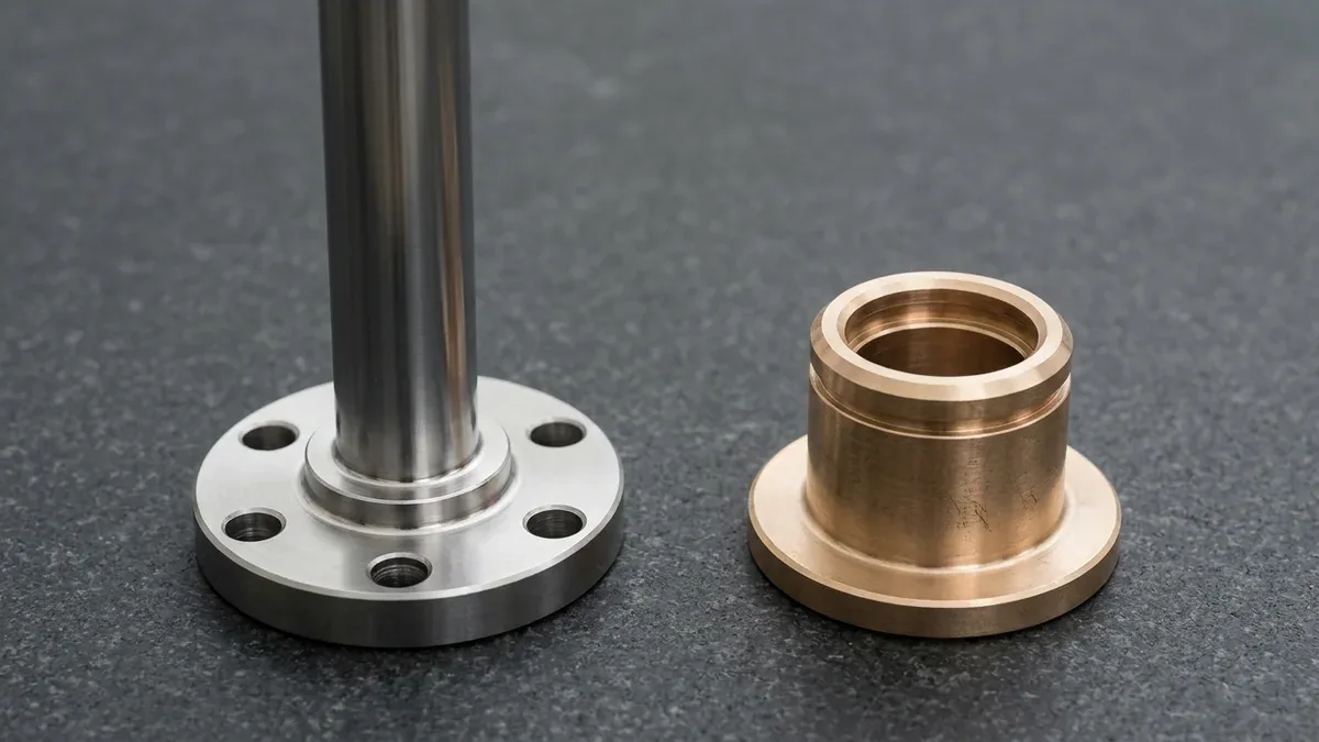
When hardened 42CrMo4, 4140, 440C, SUJ2, or 17-4PH linear shafts require 0.005 mm per 100 mm (0.0002″) straightness alongside Ra 0.2 µm finishes, our machinists lap the 60° center holes (DIN 332) after heat treatment. As shown in the cylindrical-ground 17-4PH flanged hydraulic piston rod and mating bronze gland bushing below, between-centers and centerless grinding eliminate axial bow.
| Manufacturing Process | Straightness / 100 mm | Typical L/D Ratio | Surface Roughness (Ra) | Ex-Factory Turnaround | Recommended Application / When to Choose |
|---|---|---|---|---|---|
| Unnoted General Machining (ISO 2768-mK) | 0.050–0.200 mm (Class K ≤100 mm) | ≤ 4:1 | 0.8–1.6 µm | 4 to 8 Business Days | Short standoffs, spacers, and non-mating structural brackets. |
| Standard 3-Jaw Chuck CNC Lathe | 0.015–0.030 mm (0.0006″–0.0012″) | ≤ 4:1 | 0.8–1.6 µm | 4 to 8 Business Days | Stub shafts, flanged hubs, and stepped collars without tailstock. |
| CNC Turning (Tailstock / Steady Rest) & 3/4-Axis VMC | 0.010–0.025 mm (0.0004″–0.0010″) | 4:1 to 10:1 | 0.4–0.8 µm | 4 to 8 Business Days | Drive shafts, flanged pins (— ⌀0.02 Ⓜ), and milled support rails. |
| Star Swiss-Type Lathe (Carbide Guide Bushing) | 0.005–0.010 mm (0.0002″–0.0004″) | 4:1 to 15:1 | 0.4–0.8 µm | 4 to 8 Business Days | Slender sensor probes, surgical shafts, and guide pins (⌀1.0–⌀32 mm). |
| Between-Centers / Centerless Cylindrical & Surface Grinding | 0.005–0.010 mm (0.005 mm typical) | Up to 20:1 | 0.2–0.4 µm | 7 to 12 Business Days | Hardened 42CrMo4 / 4140 / 440C / SUJ2 / 17-4PH linear shafts and rails. |
To help design engineers evaluate whether default title-block tolerances suffice before adding a custom GD&T callout, Table 4 lists the exact ISO 2768-2 Table 1 general straightness limits across Fine (H), Medium (K, our shop default under ISO 2768-mK), and Coarse (L) classes.
| Nominal Feature Length Range (mm) | Class H (Fine) | Class K (Medium — ISO 2768-mK Default) | Class L (Coarse) | Recommended Engineering Action |
|---|---|---|---|---|
Up to 10 mm | 0.02 mm | 0.05 mm (0.0020″) | 0.10 mm | Class K suffices for short bushings and collars. |
Over 10 up to 30 mm | 0.05 mm | 0.10 mm (0.0039″) | 0.20 mm | Add — 0.005 only for precision dowel pins (ISO m6/h6). |
Over 30 up to 100 mm | 0.10 mm | 0.20 mm (0.0079″) | 0.40 mm | Add explicit — ⌀0.015 Ⓜ for bearing journals and shafts. |
Over 100 up to 300 mm | 0.20 mm | 0.40 mm (0.0157″) | 0.80 mm | Class K is too loose for linear motion; specify — 0.01 / 100. |
Over 300 up to 1,000 mm | 0.30 mm | 0.60 mm (0.0236″) | 1.20 mm | Use composite callout (— ⌀0.05 / 0.015×100) and grind. |
Over 1,000 up to 3,000 mm | 0.40 mm | 0.80 mm (0.0315″) | 1.60 mm | Specify precision surface or steady-rest cylindrical grinding. |
5. How Is GD&T Straightness Verified with Zeiss CMMs, V-Blocks & Gauges?
In our climate-controlled metrology room (20°C ± 1°C), quality engineers match the inspection setup directly to the drawing’s GD&T syntax. To verify Derived Median Line Straightness at RFS (— ⌀t) per ISO 12780, our Zeiss bridge CMM scans 15 to 40 circular cross-sections and computes the minimum-zone Chebyshev (L∞) cylinder enclosing the 3D centroids.
For rapid shop-floor screening of ground shafts with negligible lobing, inspectors support both ends on matched steel V-blocks on a Grade 00 granite plate and rotate 360° under a 0.001 mm ruby lever DTI (dial indicator). Because rotation swings bow from +ebow to −ebow, actual axis bow equals half the Total Indicator Reading (ebow = TIR / 2).
📐 Worked Calculation: V-Block Dial Indicator TIR vs. Axis Straightness Bow (ebow = TIR / 2)
Governing Relationship: TIR = (+ebow) − (−ebow) = 2 · ebow | ebow = TIR / 2 (for cylindrical shafts with negligible multi-lobe roundness error)
Example: Rotating a ⌀20.0 × 200 mm ground 4140 shaft on matched steel V-blocks under a 0.001 mm dial indicator swings from +0.008 mm to −0.008 mm, giving TIR = 0.016 mm (0.00063″). Dividing by two yields true axis bow ebow = 0.016 / 2 = 0.008 mm (0.00031″), passing a — ⌀0.010 callout.
When axis straightness includes Maximum Material Condition (— ⌀t Ⓜ), inspectors measure two-point diameters with a micrometer and pass the shaft through a lapped full-form functional GO receiver gauge at Virtual Condition (DVC = DMMC + tgeo = ⌀20.07 mm). For micro Swiss-turned pins (⌀1.0–3.0 mm), a non-contact 2.5D Optical VMS prevents stylus deflection.
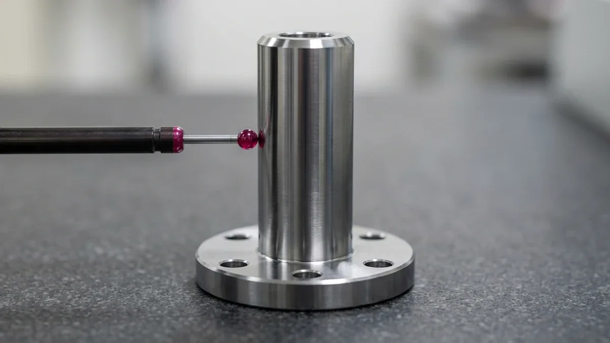
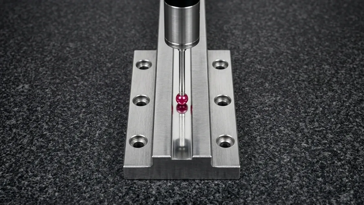
To verify Surface Line-Element Straightness (— t), flanged shafts sit on their ground base while prismatic rails rest directly on a Grade 00 black granite surface plate. As shown in the hardened 440C stainless steel linear guideway bar inspection below, a vertical Zeiss CMM ruby stylus scans longitudinal generator lines to verify 0.005 mm per 100 mm straightness.
6. What DFM Guidelines & Coating Rules Prevent Straightness Defects?
When specifying GD&T straightness (—) on long shafts or guideways, applying per-unit-length callouts without a total-length cap is a frequent DFM pitfall. Because circular arc sagitta scales with the square of length (stotal = sunit × (Ltotal / Lunit)2), an un-capped per-unit callout permits excessive end-to-end camber.
📐 Worked Calculation: Per-Unit-Length Straightness Accumulation (Square-Law Bow)
Sagitta Equation: sunconstrained = sunit × (Ltotal / Lunit)2 | Composite Callout: — ⌀0.05 / 0.015×100
Example: A 400 mm shaft (N = 4 segments) with only — ⌀0.015/100 could bow by sunconstrained = 0.015 × 42 = 0.240 mm (0.0094″). Specifying the composite callout — ⌀0.05 / 0.015×100 caps total 400 mm bow at ⌀0.05 mm and any 100 mm segment at ⌀0.015 mm.
Following five shop-floor Design for Manufacturing (DFM) and coating rules reduces grinding setups and inspection costs:
- Retain 60° Center Holes (DIN 332) & Grinding Relief Undercuts (DIN 509): Keep
60°center holes on both shaft ends and specifyDIN 509Type E/F shoulder relief undercuts whenever requiring0.005–0.010 mm per 100 mmstraightness so the rod can be cylindrical-ground between centers without wheel-corner interference. - Apply Ⓜ on Non-Rotating Clearance Pins: For static alignment shafts, guide rods, and surface-finished housings, specify
— ⌀t Ⓜto unlock MMC bonus tolerance and Functional GO Ring Gauge inspection. - Use Total Runout (⇊) Instead of Straightness on Rotating Bearing Shafts: Avoid tight axis straightness on multi-stepped rotor shafts; specify Circular Runout (↗) or Total Runout (⇊) relative to the bearing journals (
A-B) to control functional dynamic balance directly. - Account for Surface Coating Growth on Virtual Condition:
ASTM A967stainless passivation adds0.000 mm(~2 nm);ASTM B733electroless nickel builds 100% outward (+2.0ton shaft OD);MIL-A-8625 Type IIIhard anodizing on6061-T6aluminum penetrates 50% inward and builds 50% outward (+1.0ton OD); hard chrome (25–50 µm/side) is cylindrical-ground after plating. - Select Pre-Hardened or Precipitation-Hardening Grades: Specifying stress-relieved
4140-QT (28–32 HRC)or vacuum-aged17-4PH H1025/H1150avoids oil-quench distortion on long shafts.
Our in-house production schedules deliver DFM quotes within 24 hours, CNC turned/milled prototypes in 4 to 8 business days, heat-treated and cylindrical-ground shafts in 7 to 12 business days, and low-to-mid volume batches (10–1,000+ units) in 7 to 30 business days (Ex-Factory Production & Inspection Turnaround, plus 3 to 5 business days air transit).
🔗 Related GD&T & Precision Machining Engineering Guides
- Precision Cylindrical & Surface Grinding Services — Between-centers shaft grinding and guideway surface grinding to 0.005 mm per 100 mm.
- GD&T Perpendicularity (⊥): Surface vs. Axis Tolerance Guide — Controlling 90° datum orientation on flanged shafts and precision bores.
- CMM Precision Metrology & GD&T Verification Guide — Multi-point probing strategies for ASME Y14.5 and ISO 1101 form callouts.
7. Technical Engineering FAQ
Surface straightness (— 0.02 directed to the surface) creates a 2D parallel-line zone in one plane obeying ASME Y14.5 Rule #1. Axis straightness (— ⌀0.02 on the diameter dimension) creates a 3D cylindrical zone around the centerline, overriding Rule #1 and permitting Ⓜ.
For a ⌀20.00 ± 0.05 mm shaft (20.05 mm MMC, 19.95 mm LMC) with — ⌀0.02 Ⓜ, Virtual Condition equals MMC size plus straightness tolerance (⌀20.07 mm). As actual diameter shrinks toward LMC, diametral clearance adds bonus tolerance, expanding permissible axis straightness to ⌀0.12 mm.
Unless a specific GD&T frame is called out, our machine shop defaults to ISO 2768-mK. Under ISO 2768-2 Table 1 Class K, general straightness allows 0.05 mm up to 10 mm, 0.10 mm for 10–30 mm, 0.20 mm for 30–100 mm, and 0.40 mm for 100–300 mm.
Conventional CNC turning with tailstock support holds 0.010 to 0.025 mm per 100 mm straightness. Whenever a shaft requires hardness above 40 HRC, finish below Ra 0.4 µm, or straightness of 0.005 to 0.010 mm per 100 mm (0.0002″–0.0004″), between-centers cylindrical grinding is required.
Need Precision Ground Shafts or Guideways with Verified GD&T Straightness?
Upload your 3D CAD models (STEP / IGES) and 2D tolerance drawings with ASME Y14.5 or ISO 1101 straightness callouts for a complimentary manufacturability review, datum-locking strategy, and custom production quotation.
Upload Your CAD Drawings for a DFM Review & Quote →