Plastic injection molding is the cornerstone of modern mass manufacturing, capable of churning out millions of identical, structurally complex polymer parts with sub-millimeter repeatability. However, the transition from an idealized 3D CAD solid model to an operational steel or aluminum mold tool is fraught with thermal, rheological, and mechanical challenges. Molten resin behaves according to non-Newtonian fluid dynamics, cools unevenly across disparate thicknesses, and contracts during crystallization—frequently resulting in sink marks, warpage, short shots, or excessive flash.
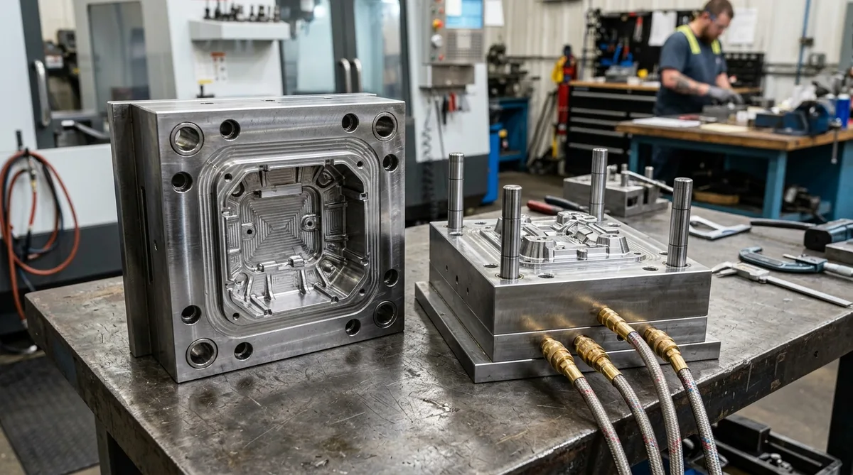
Preventing these costly tooling re-cuts requires embedding disciplined Design for Manufacturability (DFM) directly into early CAD architecture. At AS Prototypes, our tooling engineering team operates advanced CNC machining centers and wire EDM to produce rapid prototype aluminum tools and hardened steel production molds. Through hundreds of tooling programs for automotive, consumer electronics, and medical device enclosures, we have codified the seven most critical DFM rules that hardware teams must follow. Below is an engineering deep-dive into injection mold design guidelines, tooling steel selections, and defect prevention.
1. Seven Critical DFM Rules for Injection Mold Design
Rule 1: Enforce Uniform Nominal Wall Thickness
The single most influential design parameter in plastic part geometry is wall thickness uniformity. When adjacent wall sections differ in thickness, the thinner cross-sections solidify rapidly, freezing off polymer flow while the thicker core remains molten. As the thick core eventually cools and contracts, it pulls surface material inward, creating unsightly sink marks or internal vacuum voids. Maintain nominal walls within 1.5 mm to 3.5 mm across the entire component, and use gradual 3:1 chamfers or ramps when wall transitions are unavoidable.
Rule 2: Apply Sufficient Draft Angles on All Vertical Faces
As molten plastic solidifies in the mold cavity, it contracts onto the core steel while shrinking away from the cavity walls. Without draft (taper), the frictional shear during mold opening causes drag marks, scuffing, and severe mechanical stress on ejector pins. Standard engineering rules dictate:
- Smooth / Polished Finishes (SPI-A / SPI-B): Minimum 1.0° to 1.5° draft per side.
- Light Spark / Satin Textures (SPI-C / MT-11010): Minimum 2.0° to 3.0° draft per side.
- Heavy Leather / Mold-Tech Textures: Add 1.0° of draft for every 0.025 mm (0.001 in) of texture depth to prevent cavity locking during ejection.
Rule 3: Maintain Rib-to-Wall Ratios Between 40% and 60%
Structural ribs add stiffness and rigidity without inflating part weight. However, where a rib meets the nominal outer wall, the combined material intersection creates a localized thick mass. To prevent surface sink marks on class-A cosmetic faces, design rib base thickness to be 40% to 60% of the adjacent nominal wall thickness. Limit maximum rib height to three times nominal wall thickness, and incorporate at least 0.5° to 1.0° draft on rib sides.
Rule 4: Radiate All Internal Corners (Eliminate Stress Concentrations)
Sharp 90° internal corners trigger severe stress concentrations, elevating the stress concentration factor (Kt) from 1.5 up to 3.0+ and rendering parts prone to brittle impact fracture under dynamic loading. Furthermore, square corners cannot be machined directly with rotating CNC milling cutters without requiring expensive secondary sinker EDM burning. Specify an inside radius of at least 0.5 times the nominal wall thickness (R ≥ 0.5t) and an outside radius of 1.5 times wall thickness (R = 1.5t) to maintain constant wall section through bends.
Rule 5: Strategic Parting Line and Shut-Off Angle Design
The parting line defines where the ‘A’ plate (cavity) and ‘B’ plate (core) separate. Placing parting lines along natural aesthetic feature lines or bottom perimeter edges conceals residual witness lines. For through-holes or side cutouts formed by kissing shut-offs, design a minimum 3° to 5° shut-off angle. Zero-degree vertical shut-offs cause steel-on-steel friction that galls the mold face, leading to chronic flash within hundreds of cycles.
Rule 6: Optimize Gate Placement Relative to Material Flow
Gates serve as the entry orifice for pressurized resin entering the mold cavity. Correct gate placement follows these engineering imperatives:
- Gate into the thickest section of the part to ensure continuous packing pressure before the thin sections solidify;
- Direct polymer melt against a cavity wall or pin rather than open space to prevent turbulent jetting;
- Position gates so that weld lines (knit lines)—where two flow fronts meet—form in non-structural, non-cosmetic zones.
Rule 7: Engineer Balanced Conformal Mold Cooling
Cooling represents between 70% and 80% of the total injection molding cycle time. If the core side cools slower than the cavity side, differential thermal shrinkage induces residual bending stresses, causing severe part warpage after ejection. Positioning drilled water cooling circuits within 1.5 to 2.5 channel diameters from the cavity surface ensures uniform heat extraction across all mold zones, cutting cycle times by 25% while maintaining flat, distortion-free moldings.
| DFM Parameter | Recommended Standard | Engineering Risk if Violated |
|---|---|---|
| Nominal Wall Thickness | 1.5 – 3.5 mm (Resin dependent) | Differential shrinkage, internal voids, sink marks |
| Draft Angle (Smooth) | 1.0° – 1.5° per side | Ejection dragging, scuffing, pin punch-through |
| Draft Angle (Textured) | 2.0° – 5.0° (1° per 0.025 mm depth) | Cavity locking, surface micro-tearing |
| Rib-to-Wall Ratio | 40% – 60% of nominal wall | Severe cosmetic sink marks on opposite face |
| Corner Radii | Inside R ≥ 0.5t; Outside R = 1.5t | High notch stress (Kt > 3.0), premature impact cracking |
| Shut-Off Angle | 3.0° – 5.0° minimum | Steel galling, premature tooling wear, plastic flash |
2. Tooling Material Selection: Aluminum vs Pre-Hardened vs Hardened Steel
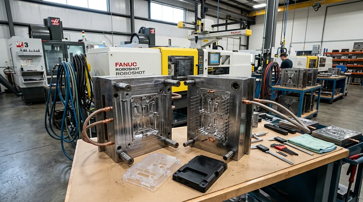
The choice of mold tooling alloy dictates upfront tooling investment, thermal cycle efficiency, and total production volume capability. At AS Prototypes, our injection molding facility manufactures tooling across three performance tiers:
| Tooling Material | Hardness (HRC) | Thermal Conductivity (W/m·K) | Estimated Tool Life (Shots) | Primary Application Window |
|---|---|---|---|---|
| Aluminum 7075-T6 | 15 – 18 HRC | 130 – 150 | 1,000 – 10,000 | Rapid prototypes, bridge tooling, fast-turn pre-series |
| P20 Pre-Hardened Steel | 28 – 34 HRC | 28 – 32 | 50,000 – 250,000 | Mid-volume production, consumer enclosures, structural housings |
| NAK80 Pre-Hardened Steel | 37 – 43 HRC | 38 – 42 | 100,000 – 300,000 | High-gloss SPI-A2 optical lenses, transparent acrylic/polycarbonate |
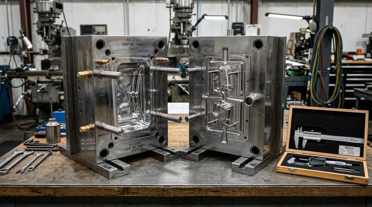
| H13 Through-Hardened Steel | 48 – 54 HRC | 24 – 28 | 500,000 – 1,000,000+ | Abrasive glass-filled engineering resins, high-volume production |
| S136 Corrosion-Resistant Steel | 48 – 52 HRC | 20 – 22 | 500,000 – 1,000,000+ | Corrosive resins (PVC, fluoropolymers), medical cleanrooms, optical mirror finishes |
Frequently Asked Questions
When a rib is attached to an exterior wall, the intersection forms a thick localized mass of plastic. During cooling, the exterior skin freezes first while the internal junction remains molten. The volumetric contraction of this molten mass pulls the outer skin inward, creating a cosmetic depression known as a sink mark. Restricting rib base thickness to 40%-60% prevents localized mass buildup.
Aluminum 7075-T6 tooling is ideal for low-volume bridge production (1,000 to 10,000 shots), functional prototype validation, and projects requiring aggressive delivery timelines. Aluminum machines up to five times faster than steel and dissipates heat significantly quicker, reducing cooling cycle times by 20% to 30%.
Warpage is caused by non-uniform volumetric shrinkage across different regions of the part. This occurs due to disparate wall thicknesses, non-uniform cooling rates between the core and cavity halves, or directional molecular orientation in fiber-filled resins. Designing uniform walls and engineering balanced cooling channels with conformal water circuits eliminates differential thermal contraction.
Bring Your Injection Mold Project to Life
From rapid prototype aluminum tooling to hardened multi-cavity production molds, AS Prototypes delivers expert DFM engineering and high-precision injection molding. Upload your 3D CAD models today for a free tooling feasibility analysis and quote.