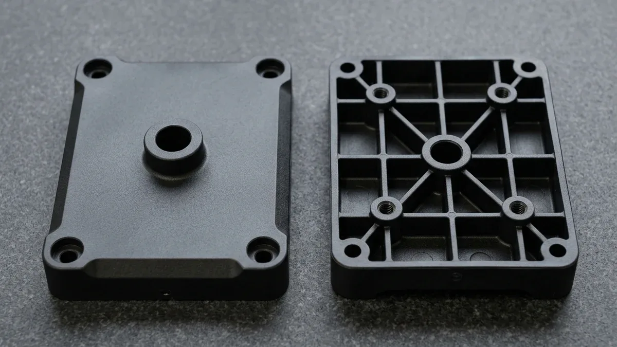
Designing plastic injection molded enclosures requires careful control of nominal wall cross-sections. Therefore, following a rigorous injection molding wall thickness guide prevents cosmetic blemishes, structural warping, and prolonged cycle times. In injection molding, molten resin cools against chilled tool steel cavity walls. Consequently, geometry dictates thermal conduction rates, differential shrinkage behavior, and internal molecular packing pressures.
Furthermore, non-uniform walls trigger uneven cooling rates that distort functional assembly dimensions. In this comprehensive technical guide, we analyze recommended resin thickness ranges, sink mark mechanics, and coring techniques. In shop-floor practice, we provide essential DFM design rules for structural ribs and gussets.
Executive Summary & Engineering Takeaways (BLUF)
- Resin-Specific Nominal Range: Thermoplastic injection molding demands uniform nominal walls (T) tailored to polymer melt flow—typically 1.8–3.2 mm (0.071″–0.126″) for ABS and PC, 1.5–2.8 mm (0.059″–0.110″, down to 0.8 mm on short flows) for PP and PA6/PA66, and 1.5–2.8 mm (0.059″–0.110″) for high-shrinkage POM acetal.
- Quadratic Cooling Time Physics: Part solidification time scales with the square of wall thickness (tcool ∝ T2 / α); doubling a local boss or flange thickness from 2.0 mm to 4.0 mm quadruples cooling duration from ~6 seconds to ~24 seconds, driving up machine-hour piece price.
- The 50%–60% Rib & Boss Base Rule: To prevent visible cosmetic sink marks opposite structural ribs and screw bosses, rib base thickness (trib) must be restricted to 0.50× to 0.60× nominal wall T, with rib height ≤3.0× T and fillet radii R = 0.25× to 0.40× T.
- Gradual 3:1 Ramp Transitions: Where functional load paths require transitioning between two different wall thicknesses, limit thickness steps to ≤15%–25% and ramp the transition over a 3:1 length-to-step slope to prevent melt-front hesitation, jetting, and differential warpage.
Article Engineering Navigation
- 1. Resin-Specific Nominal Wall Thickness Recommendations
- 2. Defects Caused by Non-Uniform Wall Thickness
- 3. Coring Techniques and Wall Transition Rules
- 4. Precision DFM Rules for Ribs, Bosses, and Fillets
- 5. Quantitative Cooling Time, Volumetric Shrinkage & Rib-to-Wall Ratio Mechanics
- 6. How Do You Eliminate Sink Marks, Vacuum Voids, and Part Warpage in Molded Enclosures?
- 7. When NOT to Use Thin-Wall Injection Molding & Wall Thickness DFM Checklist
- 8. Technical Engineering FAQ
1. Resin-Specific Nominal Wall Thickness Recommendations
Core Physical Principles and Shop-Floor Execution
Each thermoplastic resin exhibits distinct melt viscosity, thermal conductivity, and volumetric shrinkage characteristics. For example, amorphous polymers like polycarbonate (PC) and ABS flow smoothly across moderate wall sections. Conversely, semi-crystalline resins like polypropylene (PP) and polyoxymethylene (POM) undergo substantial volumetric shrinkage upon crystallization.
Therefore, semi-crystalline polymers require tighter wall thickness discipline to prevent internal vacuum voids. The engineering reference matrix below details baseline, minimum, and maximum recommended wall thicknesses across common industrial resins.
| Polymer Family & Grade | Resin Structure | Linear Mold Shrinkage (%) | Minimum Wall (mm) | Recommended Nominal Wall (mm) | Maximum Safe Wall (mm) |
|---|---|---|---|---|---|
| ABS (General Purpose) | Amorphous | 0.4% to 0.7% | 1.1 mm | 2.0 mm to 3.0 mm | 3.8 mm |
| Polycarbonate (PC) | Amorphous | 0.5% to 0.8% | 1.0 mm | 1.8 mm to 3.2 mm | 4.0 mm |
| Polypropylene (PP) | Semi-Crystalline | 1.2% to 2.2% | 0.8 mm | 1.5 mm to 2.8 mm | 3.5 mm |
| Polyamide Nylon (PA66) | Semi-Crystalline | 1.0% to 1.8% | 0.8 mm | 1.5 mm to 2.5 mm | 3.2 mm |
| Polyoxymethylene (POM Acetal) | Semi-Crystalline | 1.8% to 2.5% | 0.8 mm | 1.5 mm to 2.8 mm | 3.2 mm |
| PEEK (High Performance) | Semi-Crystalline | 1.2% to 1.5% | 1.2 mm | 1.8 mm to 3.0 mm | 3.5 mm |
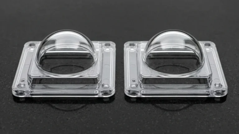
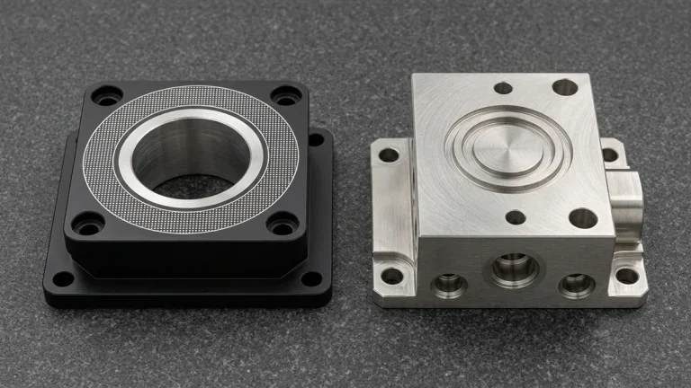
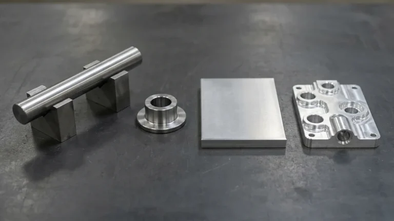
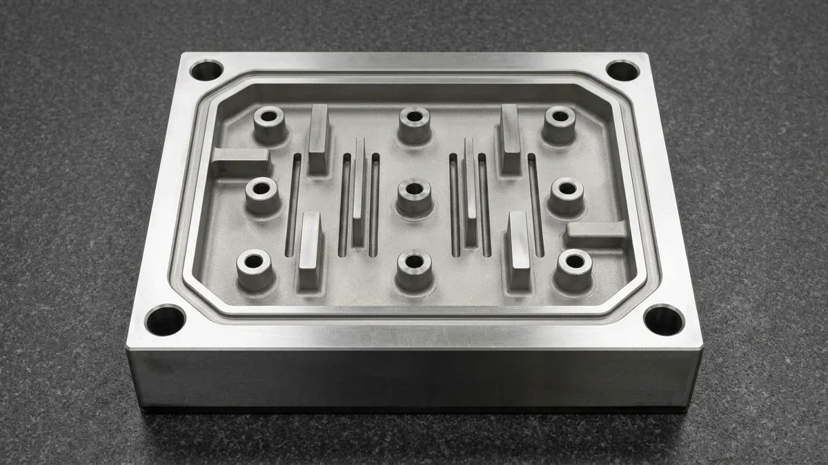
As demonstrated in the hardened H13 tool steel injection mold core insert resting flat on the granite surface plate in Figure 1, standing rectangular core-out projections work in tandem with narrow spark-eroded rib-forming slots and cored cylindrical boss sleeves to keep polymer wall sections uniform and eliminate localized thermal mass accumulation.
2. Defects Caused by Non-Uniform Wall Thickness
Resin Melt Flow Ratio (L/t) and Viscosity Boundaries
Abrupt wall thickness variations generate severe cosmetic and dimensional defects in molded components. First, thick solid sections take significantly longer to cool than adjacent thin perimeter walls. As the molten plastic core contracts, it pulls the solidified outer skin inward, creating unsightly sink marks.
Second, differential cooling induces severe residual internal stresses. Thin sections freeze rapidly while thick sections remain molten. Consequently, uncoordinated thermal shrinkage forces the entire part to twist or bow out of plane. Explore our high-precision rapid tooling and injection molding services to eliminate molding defects.
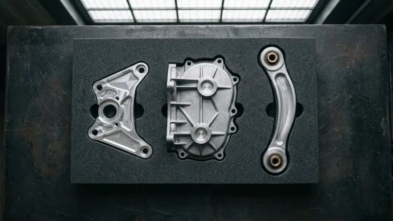
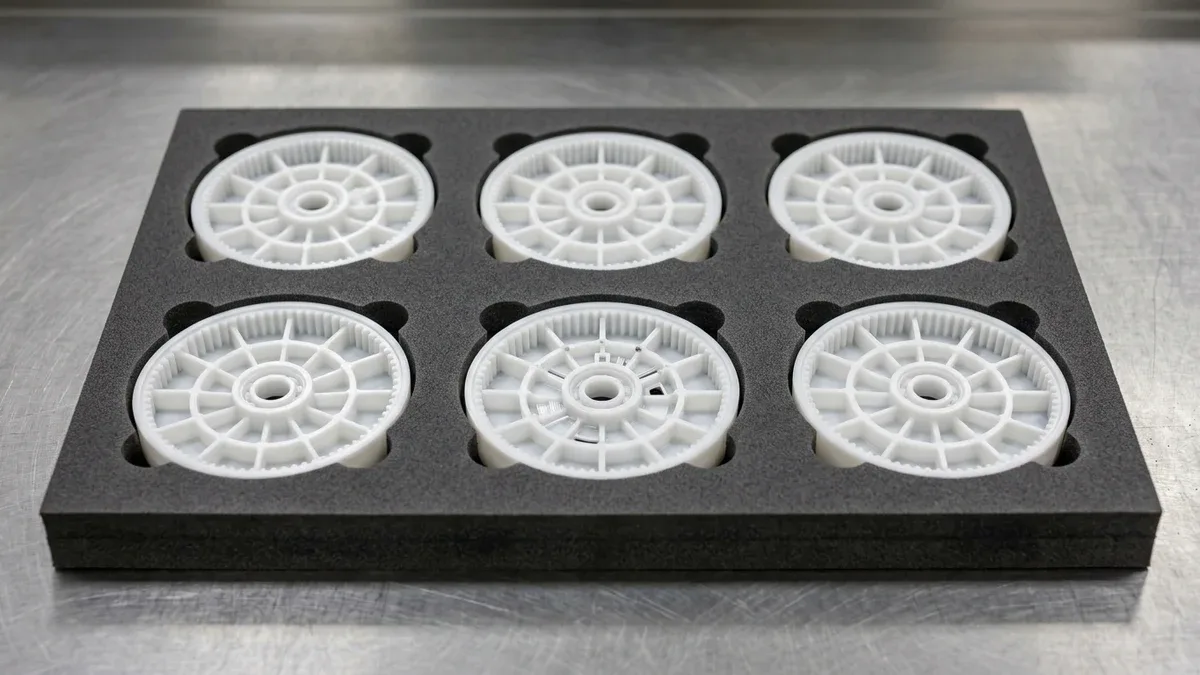
As demonstrated in Figure 2, six injection-molded white POM acetal gear housings staged in an EVA foam tray utilize symmetrical radial wall-coring pockets between the outer gear rim and central bearing hub. Maintaining a uniform 2.0 mm nominal wall section eliminates cosmetic sink marks and differential shrinkage warpage.
3. Coring Techniques and Wall Transition Rules
Cooling Time Squared Dependency and Cycle Economics
Eliminating heavy cross-sections requires coring out massive structural bosses and thick corner gussets. Specifically, mold designers use moving core pins to remove excess plastic from the underside of thick features. Coring preserves uniform nominal wall thickness while maintaining external structural stiffness.
Furthermore, when geometric requirements necessitate wall thickness changes, avoid sharp abrupt steps. Instead, incorporate gentle chamfered or filleted ramps with slopes not exceeding 3:1. Gradual thickness transitions prevent molten melt flow hesitation and eliminate localized stress concentrations. In addition, our manufacturing facility produces precision enclosures for consumer electronics and smart appliances.
4. Precision DFM Rules for Ribs, Bosses, and Fillets
Practical Design-for-Manufacturing (DFM) Guidelines
Adding reinforcement ribs increases part rigidity without thickening nominal wall sections unnecessarily. First, design rib base thickness between 50 and 60 percent of the adjoining nominal wall. Restricting rib thickness prevents localized thermal mass accumulation that produces sink marks on opposite cosmetic faces.
Second, limit maximum rib height to three times the nominal wall thickness. Overly tall ribs impede tool ventilation, causing gas burns and short shots. Finally, apply generous internal radii of 25 to 50 percent of wall thickness to all corner intersections.
5. Quantitative Cooling Time, Volumetric Shrinkage & Rib-to-Wall Ratio Mechanics
Fourier Thermal Diffusion Law and Wall Thickness Squared Dependency
In thermoplastic injection molding, cooling time accounts for 60% to 80% of the total press cycle and scales directly with the square of maximum wall thickness (h²). Doubling a housing’s nominal wall thickness from 2.0 mm (0.080 in) to 4.0 mm (0.157 in) does not merely double cooling time—it quadruples the time required for the molten polymer core to solidify down to its heat deflection ejection temperature.
• One-Dimensional Fourier Cooling Time: tcool ≈ [ h² / (π² × αeff) ] × ln[ (4 / π) × (Tmelt − Tmold) / (Teject − Tmold) ] [sec]
• Anti-Sink Rib Root Thickness Rule: trib = 0.50 × twall (Glossy cosmetic Class A) to 0.65 × twall (Textured structural)
• Coring Stiffness Advantage (Moment of Inertia): Iribbed ∝ b × H³ / 12 (Doubling rib height H increases bending stiffness 8× with minimal mass)
Why Thick Intersections Trigger Surface Sink Marks vs. Internal Vacuum Voids
When a 100% full-thickness structural rib intersects a nominal outer wall, the inscribed circle at the T-junction increases by 40%–60%, creating a localized thermal hot spot.
If the outer polymer skin remains soft while the thick core undergoes linear mold shrinkage of 0.4%–2.5% (corresponding to up to 6%–18% total melt-to-solid pvT volumetric contraction depending on amorphous vs. semi-crystalline resin), atmospheric pressure pushes the cosmetic outer skin inward into a visible sink mark. Conversely, if cold mold steel freezes a rigid outer skin early (as in Polycarbonate or glass-filled Nylon), internal shrinkage pulls the molten center apart, leaving an internal vacuum bubble void.
Amorphous vs. Semi-Crystalline Resin Wall Thickness Windows
Amorphous resins (ABS, PC, PC/ABS, PMMA, PEI) exhibit low, isotropic linear mold shrinkage (0.4%–0.7%) and tolerate moderate wall variations up to ±20%. By contrast, semi-crystalline engineering polymers (POM/Acetal, PA66/Nylon, PBT, PEEK, PP) undergo high crystalline linear mold shrinkage (1.5%–2.5%), making strict wall uniformity (±10%) mandatory to prevent differential warpage and twisting.
6. How Do You Eliminate Sink Marks, Vacuum Voids, and Part Warpage in Molded Enclosures?
Coring Out Screw Bosses, Gussets, and Heavy Mounting Pads
Un-cored screw bosses and thick mounting flanges are the #1 cause of cosmetic rejection in custom injection molding. To eliminate localized mass accumulation, mold designers core out the base of every screw boss so its annular wall thickness equals 0.60× the adjacent nominal wall, and connect the boss to nearby side walls using tapered triangular gussets rather than thick solid webs.
| Observed Defect / Symptom | Physical Root Cause | Quantitative Process Threshold | Corrective Shop-Floor Action | Inspection Verification Method |
|---|---|---|---|---|
| Visible sink mark trench on cosmetic face opposite a rib | Excessive T-junction thermal mass shrinking after gate freeze-off | Rib root thickness trib > 65% of nominal wall twall or fillet R > 0.5×twall | Reduce rib base thickness to 50%–55% of nominal wall and apply SPI D-2 / VDI 27 matte texture on cosmetic face | Optical profilometer surface depression scan (< 0.015 mm sink depth) |
| Internal vacuum voids inside thick mechanical bosses | Rigid frozen outer skin preventing inward relief of core shrinkage | Localized section thickness > 4.5 mm (0.177 in) in PC, PSU, or POM | Core out thick sections to uniform 2.0–3.0 mm shells or switch to nitrogen gas-assisted molding | Cross-sectional destructive microtome cut or industrial X-ray CT scan |
| Flow hesitation and short shots in thin ribs or louvers | Melt front preferentially filling thick channels while thin ribs freeze | Thickness ratio between adjacent flow paths exceeds 2.5:1 | Add gradual 3:1 tapered ramp transitions and increase thin-section thickness within L/t flow-ratio limits | Moldflow fill-pack simulation and short-shot progression study |
| Saddle warpage and corner bow on rectangular covers | Differential cooling shrinkage between thick flanges and thin center panels | Wall thickness variation > ±15% in semi-crystalline PA66, POM, or PBT | Equalize wall thickness across entire part envelope and balance cavity/core conformal cooling channels | Zeiss CMM 3D optical surface scan against nominal CAD envelope |
Gradual 3:1 Ramp Transitions Between Necessary Thickness Steps
When a functional component genuinely requires stepping from a 1.5 mm (0.060 in) housing wall to a 3.0 mm (0.118 in) structural load flange, abrupt 90° steps cause melt flow turbulence, trapped gas burn marks, and high shear residual stress. Designing a smooth 3:1 tapered ramp (4.5 mm transition length for a 1.5 mm step) allows the polymer melt front to pack smoothly from the thick gate zone into thinner extremities.
7. When NOT to Use Thin-Wall Injection Molding & Wall Thickness DFM Checklist
When NOT to Force Parts Into Thin-Wall (< 1.2 mm) Conventional Injection Molding
Product engineers should avoid forcing components into ultra-thin or extreme-thick conventional injection molding under three conditions:
- Long Flow Paths Above L/t = 180:1 in High-Viscosity Resins (PC / Ultem): Attempting to fill a 250 mm laptop panel at 1.0 mm wall thickness in standard Polycarbonate requires extreme injection pressures (> 1,800 bar) that lock in severe molded-in stress; either add multiple hot-runner gates, switch to high-flow PC/ABS, or increase nominal wall to 2.0–2.5 mm.
- Heavy Structural Blocks Over 8.0 mm (0.315 in) Solid Cross-Section: Conventional injection molding cannot pack solid blocks thicker than 8 mm without multi-minute cycle times and severe voids; use structural foam molding, CNC machining from annealed billet, or heavy-wall coring.
- Low-Volume Batches Under 100 Units With Zero Draft Permitted: If an assembly cannot tolerate the 0.5°–1.5° draft angles required to eject thin ribs without drag marks, machine the prototypes directly via 3-axis/4-axis CNC milling.
Four-Step Injection Molding Wall-Thickness DFM Verification Protocol
- Lock Nominal Wall Thickness to Resin Flow Ratio (L/t): Choose a single target nominal wall between 1.5 mm and 3.0 mm (0.060–0.118 in) based on resin viscosity and maximum gate-to-edge flow path length.
- Core Out All Heavy Bosses and Limit Rib Roots to 50%–60%: Keep rib height ≤ 3.0× nominal wall thickness, add 0.5°–1.0° draft per side, and use a small 0.25–0.40×twall fillet radius at the rib root to prevent T-junction mass buildup.
- Maintain Uniform Corner Wall Thickness on Bends: Always set the outer corner radius equal to the inner corner radius plus nominal wall thickness (Router = Rinner + twall, with Rinner ≥ 0.5×twall) so corner walls never thicken at 90° turns.
- Position Gates at the Thickest Functional Zone: Direct the mold gate into the thickest structural section so packing pressure remains active longest where volumetric shrinkage is highest.
🔗 Related Injection Molding, Rapid Tooling & Defect Prevention Guides
8. Technical Engineering FAQ
Molten thermoplastics undergo 0.4%–2.5% linear shrinkage as they cool from 240°C–300°C, causing thick sections to solidify 5×–6× slower and pull adjacent skins inward. Maintain wall uniformity within ±10%–15% of the nominal gauge and apply 3:1 gradual transition ramps wherever thickness steps are required.
Reinforcing ribs must maintain a base thickness of 0.50×–0.60× the nominal wall (T) and a maximum height of 2.5×–3.0× T to boost stiffness without opposite-side sink marks. Apply 0.5°–1.0° draft per side, a 0.25T–0.40T base radius, and 2.0×–3.0× T spacing for mold cooling pins.
Merging a screw boss directly into an outer wall creates a thermal mass concentration that pulls visible sink marks across the cosmetic A-surface. Offset the boss inward by 2.0× T, keep boss walls at 0.60× T, and connect it using 0.50× T doghouse gusset ribs.
Exceeding a resin’s flow-length-to-thickness ratio (L/t of 80:1–120:1 for PC or 150:1–250:1 for PP/PA) freezes skin layers prematurely, causing short shots, 1,800+ bar cavity pressures, and weak weld lines. Increase the nominal wall to 1.5–2.5 mm or add multi-gate drops to keep L/t within safe limits.
Ready to Validate Your CAD Design for Precision Manufacturing?
Upload your 3D CAD models (STEP, IGES, SolidWorks) and 2D engineering drawings for a comprehensive DFM engineering review and custom quotation from our in-house CNC machining and prototyping team.
Request a Custom DFM Review & Quote →