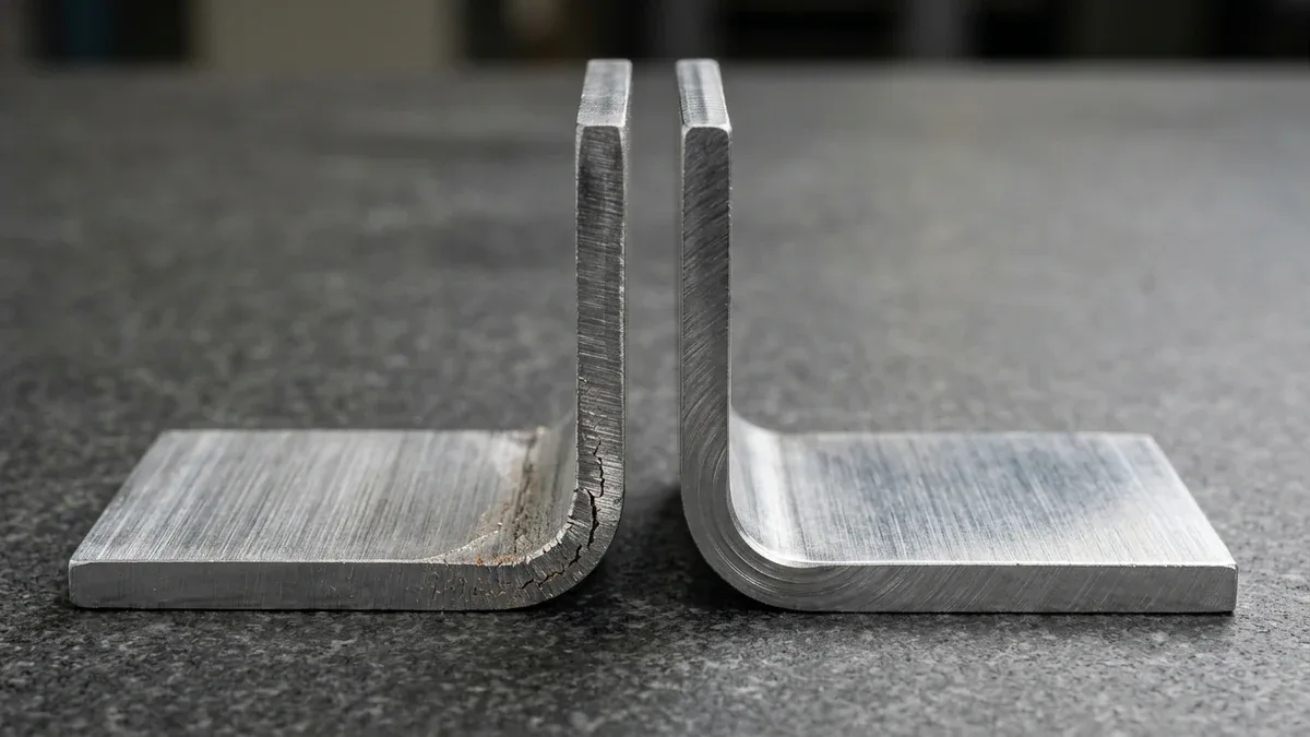
Sheet metal grain direction is the primary metallurgical variable governing minimum inside bend radii, elastic springback, and outer-fiber fracture limits during Computer Numerical Control (CNC) press brake forming. High-tonnage mill rolling elongates crystal lattices and intermetallic precipitates parallel to the coil feed axis, creating mechanical anisotropy that triggers outer-radius cracking.
During CNC press brake air bending, the inner bend surface undergoes triaxial compression while the outer surface experiences uniaxial tensile strain. Bending perpendicular to the rolling axis (90° transverse across the grain) stretches ductile fibers along their length, whereas bending parallel (0° along the grain) splits weak intergranular boundaries.
In our in-house sheet metal shop, we prevent bend cracking across standard metric stock gauges of 0.2 to 12.0 mm (0.008 to 0.472 in.). Through custom sheet metal fabrication and press brake bending, we lock Design for Manufacturability (DFM) nesting angles and DIN 6935 K-factors, verifying blanks on 2.5D Optical Video Measuring Systems (VMS).
Executive Summary & Engineering Takeaways (BLUF)
- Transverse (90°) vs. Parallel (0°) Radii: Transverse bends (90° across grain) allow Rmin = 1.0T in 5052-H32 aluminum, 0.8T–1.0T in SUS304 (2B) stainless, 0.5T–0.8T in SPCC/DC01/Q235B steel, and 0.5T–1.5T in C11000/C2680/C17200 copper alloy strips; parallel bends (0° along grain) require 1.5T in 5052-H32, 1.5T–2.0T in SUS304, and 1.0T–1.2T in SPCC/DC01.
- 6061-T6 Fracture Warning & 5052-H32 Substitution: Outer tensile strain follows εouter = 1 ÷ [(2Rin ÷ T) + 1] (33.3% at 1.0T); bending 6061-T6 at 1.0T–2.0T causes catastrophic outer-radius fracture (Rmin = 3.0T–4.0T transverse, 4.5T–6.0T parallel), so specify 5052-H32 (228 MPa tensile) for formed enclosures and brackets.
- 45° Diagonal Nesting & Tear-Drop Reliefs: Orient multi-axis 4-flange trays, box chassis, and bidirectional C2680-1/2H or C17200 spring tabs at a 45° diagonal bias during fiber laser nesting, paired with tear-drop corner bend reliefs (W ≥ T, min 1.0 mm; D ≥ Rin + T).
- DIN 6935 Flat Pattern & V-Die Calibration: Select press brake V-dies of V = 6T–8T (T ≤ 3.0 mm), V = 8T–10T (T = 4.0–6.0 mm), or V = 10T–12T (T > 6.0 mm) with natural air-bent Rin ≈ 0.156V–0.165V and DIN 6935 K-factors of 0.33–0.45, computing BA = (π ÷ 180) × θ × (Rin + K × T) and BD = 2 × OSSB − BA.
- Non-Contact Optical Metrology & Turnaround: Verify 2D laser-cut flat blanks (±0.05–0.10 mm) on 2.5D Optical VMS and formed bends (±0.20–0.30 mm, ±0.5°–1.0°) using Grade 00 90° knife-edge squares, vernier bevel protractors, precision radius gauges, Class ZZ GO/NO-GO pin/thread gauges, checking fixtures, and mating fit-up fixtures (4–8 business days bare, 7–12 business days finished Ex-Factory).
Article Engineering Navigation
- 1. How Does Sheet Metal Grain Direction Govern Transverse vs. Parallel Bending?
- 2. Why Does 6061-T6 Sheet Metal Crack Along the Grain Compared to 5052-H32?
- 3. What Are the Minimum Bend Radius (Rmin / T), K-Factor & Springback Limits?
- 4. When Should You Use 45° Diagonal Laser Nesting & Corner Bend Reliefs?
- 5. How Do You Calculate DIN 6935 Flat Patterns, V-Die Openings & K-Factors?
- 6. How Are Formed Sheet Metal Bends Inspected & Finished on the Shop Floor?
- 7. Technical Engineering FAQ
1. How Does Sheet Metal Grain Direction Govern Transverse vs. Parallel Bending?
Sheet metal rolling anisotropy is a crystallographic condition where hot or cold mill reduction elongates metallic grains into fibrous stringers aligned with the coil feed axis, reducing longitudinal bend ductility by 25% to 55%. Across standard metric stock gauges from 0.2 to 12.0 mm (0.008 to 0.472 in.), non-metallic inclusions align into longitudinal bands.
In cold-rolled carbon steels (SPCC) and structural plates (Q235B), rolling draws manganese sulfide (MnS) and silicate inclusions into microscopic longitudinal filaments. In aluminum alloys (5052-H32 and 6061-T6), mill rolls fragment iron-rich intermetallics and magnesium-silicide (Mg2Si) precipitates into directional trails along the 0° coil rolling axis.
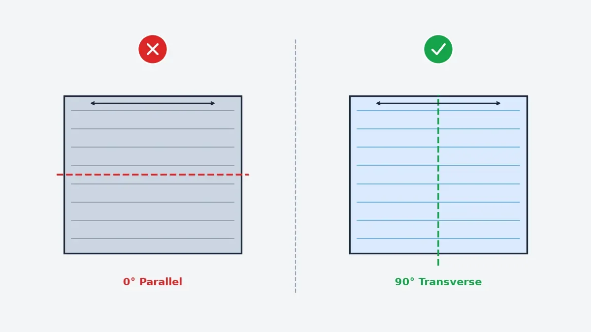
When a press brake punch descends into a bottom V-die, the principal tensile strain acts perpendicular to the bend axis. Orienting the bend line at 90° transverse (perpendicular to the rolling grain) aligns principal tensile stress parallel to the elongated fibers, stretching continuous ductile crystal lattices without intergranular separation.
Conversely, orienting the bend line at 0° parallel (longitudinal to the rolling grain) forces principal tensile strain to pull perpendicular across weak grain boundaries and inclusion stringers. Under outer-fiber tension, micro-voids nucleate along elongated precipitates and coalesce into visible orange-peel roughening, surface crazing, or catastrophic full-thickness fracture.
As shown in the DFM schematic below, a 0° parallel bend concentrates tensile stress across intergranular planes and triggers outer fracture, whereas a 90° transverse bend pulls along interlocking fibers. Transverse bending permits 35% to 60% tighter inside radii (Rmin) while requiring 8% to 12% higher press brake tonnage.
2. Why Does 6061-T6 Sheet Metal Crack Along the Grain Compared to 5052-H32?
Outer-fiber engineering tensile strain during air bending follows εouter = 1 ÷ [(2Rin ÷ T) + 1], reaching 50.0% at 0.5T, 33.3% at 1.0T, 25.0% at 1.5T, and 20.0% at 2.0T. Because precipitation-hardened 6061-T6 exhibits only 8% to 10% elongation, tight 1.0T to 2.0T bends exceed outer-fiber fracture limits.
Artificial aging in 6061-T6 precipitates brittle Mg2Si particles along grain boundaries. Bending T = 2.0 mm 6061-T6 at Rin = 1.0 mm (0.5T, εouter = 50.0%) or 2.0 mm (1.0T, 33.3%) causes immediate outer fracture, whereas Rin = 6.0 mm (3.0T–4.0T transverse, εouter = 14.3%) or 4.5T–6.0T parallel (7.7% at 6.0T) is safe.
During DFM review, our engineers specify strain-hardened 5052-H32 aluminum (228 MPa / 33.1 ksi ultimate tensile strength, 193 MPa / 28.0 ksi yield strength) for formed enclosures and brackets. Solid-solution magnesium strengthening gives 5052-H32 12% to 18% elongation, supporting crack-free Rmin = 1.0T transverse and 1.5T parallel bends.
Never specify 6061-T6 for tight 1.0T sheet metal bends or 180° hems; reserve 6061-T6 for flat laser-cut plates or CNC-machined structural blocks. Where 6061 alloy chemistry is mandatory for tight forming, blanks must be cold-formed in annealed 6061-O or freshly quenched 6061-T4 temper before post-form artificial aging.
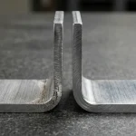
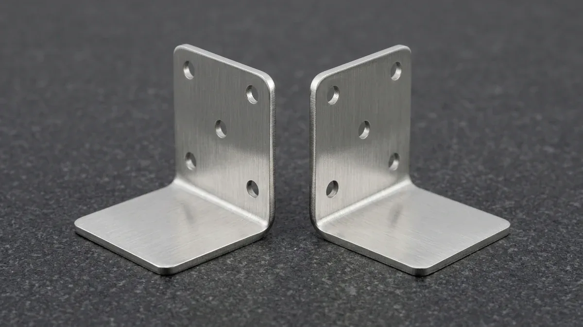
In austenitic SUS304 and SUS316L stainless steel (2B or #4 brushed finish, Ra 0.4–0.8 µm / 16–32 µin), grain direction governs both strain-induced martensitic work hardening and cosmetic brush continuity. As shown on our granite plate below, forming 2.5 mm (0.098 in.) brushed 304 L-brackets at 90° transverse across an R2.5 mm bend yields crack-free arcs.
For electrical busbars and EMI/RF spring contacts in C11000 (T2) copper, C2680-1/2H brass, and C17200 beryllium copper (0.15 to 0.5 mm / 0.006 to 0.020 in.), unidirectional fingers bend 90° transverse to the grain, whereas bidirectional orthogonal spring tabs require 45° diagonal nesting to prevent fatigue fracture.
3. What Are the Minimum Bend Radius (Rmin / T), K-Factor & Springback Limits?
Specifying the minimum inside bend radius (Rmin) relative to nominal sheet thickness (T) requires matching alloy temper against grain orientation (transverse 90° versus parallel 0°), DIN 6935 K-factors, and elastic springback angles. Across standard metric stock gauges, the natural air-bent inside radius equals Rin ≈ 0.156V to 0.165V of the V-die opening (V).
In cold-rolled SPCC / DC01 (0.5–3.0 mm) and hot-rolled SPHC (1.5–6.0 mm) or Q235B steel, ferritic ductility allows Rmin = 0.5T–0.8T transverse and 1.0T–1.2T parallel. For electro-galvanized (SECC) and hot-dip galvanized (SGCC) steel (0.5–3.0 mm) plus SUS301 spring strips (0.1–0.4 mm), we lock grain direction to prevent zinc flaking or fatigue.
| Alloy, Temper & Standard Gauge Range | Transverse Rmin/T (90°) | Parallel Rmin/T (0°) | DIN 6935 K-Factor | Springback (90° Bend) | Recommended Application / When to Choose |
|---|---|---|---|---|---|
| 5052-H32 Aluminum (0.5–6.0 mm) | 1.0T | 1.5T | 0.38–0.42 | 1.5°–2.5° | Primary choice for formed aluminum enclosures, U-brackets, and chassis. |
| 6061-T6 Aluminum (1.0–12.0 mm) | 3.0T–4.0T | 4.5T–6.0T | 0.42–0.45 | 3.0°–4.5° | Flat laser plates only; fractures at 1.0T–2.0T (substitute 5052-H32). |
| SPCC (0.5–3.0 mm) & SPHC (1.5–6.0 mm) / Q235B | 0.5T–0.8T | 1.0T–1.2T | 0.36–0.41 | 1.0°–2.0° | Indoor server racks, structural weldments, and powder-coated cabinets. |
| SECC / SGCC Galvanized (0.5–3.0 mm) | 0.5T–0.8T | 1.0T–1.2T | 0.37–0.41 | 1.2°–2.2° | Corrosion-resistant internal chassis and power supply sub-plates. |
| SUS304 / 316L (0.4–8.0 mm) & SUS301 (0.1–0.4 mm) | 0.8T–1.0T | 1.5T–2.0T | 0.33–0.38 | 2.5°–4.0° | Medical enclosures, food-grade housings, and outdoor NEMA cabinets. |
| C11000 (T2-H02) Copper (0.2–6.0 mm) | 0.5T–0.8T | 1.0T–1.5T | 0.38–0.42 | 1.0°–2.0° | High-current EV battery busbars, grounding straps, and thermal shunts. |
| C17200 Beryllium Copper (0.15–0.5 mm) | 1.0T–1.5T | 2.0T–3.0T | 0.40–0.44 | 3.5°–6.0° | EMI/RF shielding fingerstock and spring contacts (45° for 2-axis tabs). |
| C2680-1/2H (H02) Brass (0.15–4.0 mm) | 0.8T–1.0T | 1.5T–2.0T | 0.38–0.42 | 1.5°–2.5° | Terminal clips, RF shielding cans, and bidirectional orthogonal spring tabs. |
Grain orientation also alters elastic springback (Δθs) and neutral-axis K-factors. Because transverse yield strength exceeds longitudinal yield strength by 6% to 12% in rolled sheet, 90° transverse bends exhibit 15% to 25% greater elastic springback than 0° parallel bends, requiring dynamic CNC press brake crowning and over-bend angle compensation.
When designing 180° flattened hems for panel edge stiffening, specify 5052-H32 aluminum or SPCC steel with the hem fold line oriented 90° perpendicular to the rolling grain. Leave a 0.5T to 1.0T teardrop inner gap on 5052-H32 and SUS304 hems to prevent outer-fiber shear splitting during flattening.
4. When Should You Use 45° Diagonal Laser Nesting & Corner Bend Reliefs?
Multi-axis 4-flange trays, U-channels with end tabs, and box-pan chassis contain bend lines along both X and Y axes. Standard orthogonal (0°/90°) fiber laser nesting aligns two opposing flanges at 90° transverse to the grain while forcing the two perpendicular flanges to bend at 0° parallel to the grain.
Rotating multi-axis flat patterns to a 45° diagonal bias during CAM fiber laser cutting and sheet nesting equalizes tensile strain, K-factors, and springback angles across all four orthogonal walls. Although 45° diagonal nesting reduces sheet utilization from 82%–90% to 68%–76%, it eliminates parallel-grain corner cracking on tight 1.0T–1.2T enclosures.
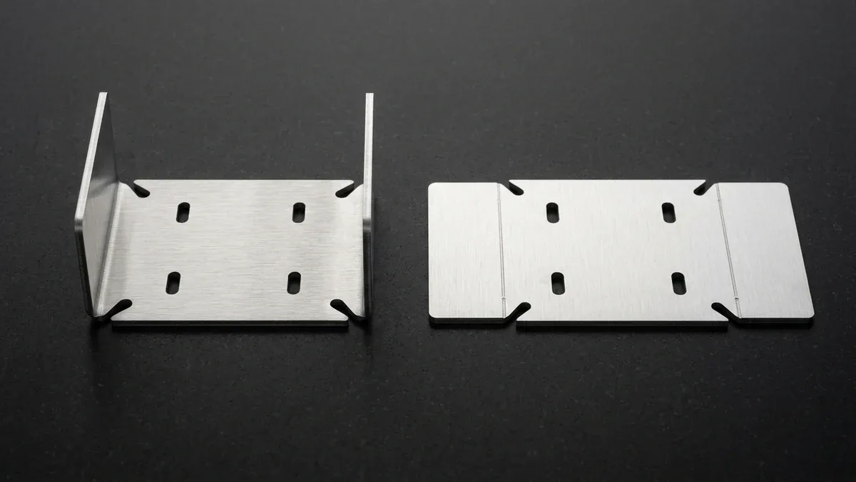
Where orthogonal flanges meet at box corners, triaxial stress concentration tears the metal unless laser-cut circular or tear-drop corner bend relief notches isolate the bend zones. Size corner bend reliefs with notch width W ≥ T (minimum 1.0 mm / 0.039 in.) and depth D ≥ Rin + T past the tangent line.
The side-by-side 2.0 mm (0.079 in.) 5052-H32 aluminum comparison on our granite inspection plate below illustrates this flat-pattern unfolding rule. The 2D fiber-laser-cut blank (right) integrates four corner tear-drop bend-relief notches along the fold lines, producing the crack-free 90° formed U-channel chassis bracket (left).
To prevent hole ovality and flange pull-in during air bending, position circular mounting holes and PEM fastener pilot holes at a minimum edge-to-bend distance of Dhole ≥ 2.0T + Rin (and ≥ 3.0T + Rin for elongated slots). Maintain minimum straight flange height at Hmin ≥ 0.7V (or 4T + Rin) across the V-die shoulders.
| Laser Nesting Strategy | Bend-to-Grain Angle | Sheet Yield (%) | Material Cost Ratio | Angular Repeatability | Recommended Application / When to Choose |
|---|---|---|---|---|---|
| 0°/90° Orthogonal Transverse | 90° Transverse | 82%–90% | 1.00x Baseline | ±0.5° (Single Axis) | Unidirectional L-brackets, hat channels, Z-brackets, and spring clips. |
| 45° Diagonal Bias Nesting | 45° on X & Y Axes | 68%–76% | 1.12x–1.20x | ±0.5° Across All 4 Walls | Multi-axis 4-flange trays, box pans, and orthogonal U-channel brackets. |
| Cosmetic Grain-Locked (#4) | 0°/90° Fixed Arrow | 74%–84% | 1.08x–1.15x | ±0.5°–0.8° (Per-Axis Offset) | Visible #4 brushed 304 stainless bezels and brushed anodized faceplates. |
| Random Auto-Nesting (Avoid) | 0°–90° Uncontrolled | 88%–94% | 0.95x (High Scrap Risk) | ±1.5°–2.5° Drift | Flat unbent shims and washers only; never use for formed brackets. |
5. How Do You Calculate DIN 6935 Flat Patterns, V-Die Openings & K-Factors?
Accurate flat-pattern unfolding in SolidWorks, Inventor, or AutoCAD requires matching your CAD K-factor and inside radius (Rin) to the shop-floor CNC press brake V-die opening. Our engineers select bottom dies of V = 6T–8T for T ≤ 3.0 mm, V = 8T–10T for T = 4.0–6.0 mm, and V = 10T–12T for T > 6.0 mm or high-strength alloys.
In CNC air bending, the natural inside bend radius follows Rin ≈ 0.156V to 0.165V across standard gauges (~0.156V for 5052-H32 aluminum, ~0.165V for SPCC/DC01 carbon steel, and ~0.20V for higher-springback SUS304 stainless steel). Selecting a punch radius smaller than 0.8T coins a sharp longitudinal crease along the inner bend surface.
As illustrated in the 90° bend cross-section schematic below, triaxial compression on the inner bend surface shifts the zero-strain neutral axis inward from the 0.50T mid-plane to t = K × T. This inward shift defines the DIN 6935 Bend Allowance arc along radius Rn = Rin + K × T.
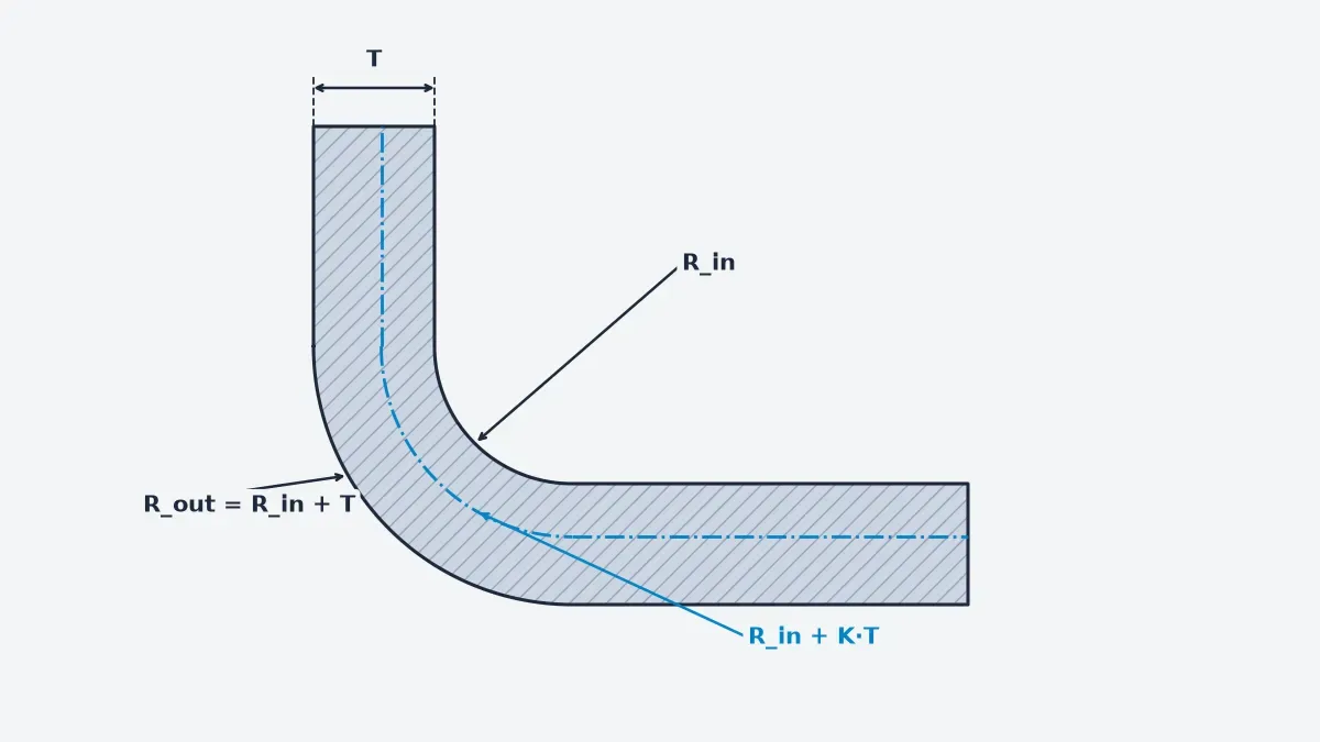
| Sheet Thickness T (mm / in.) | Standard V-Die Opening V | Natural Air-Bent Rin (mm) | Min. Straight Flange Hmin | Min. Hole-to-Bend Dhole | Min. Corner Relief (W × D) |
|---|---|---|---|---|---|
| 0.5 mm (0.020 in.) | 4.0 mm (8T) | 0.6–0.8 mm | 3.0 mm (0.118 in.) | 1.8 mm (0.071 in.) | 1.0 × 1.3 mm |
| 1.0 mm (0.039 in.) | 6.0–8.0 mm (6T–8T) | 1.0–1.3 mm | 4.5–5.5 mm (0.177–0.217 in.) | 3.0–3.3 mm (0.118–0.130 in.) | 1.0 × 2.3 mm |
| 1.5 mm (0.059 in.) | 10.0–12.0 mm (6.7T–8T) | 1.5–2.0 mm | 7.0–8.5 mm (0.276–0.335 in.) | 4.5–5.0 mm (0.177–0.197 in.) | 1.5 × 3.5 mm |
| 2.0 mm (0.079 in.) | 12.0–16.0 mm (6T–8T) | 2.0–2.6 mm | 8.5–11.5 mm (0.335–0.453 in.) | 6.0–6.6 mm (0.236–0.260 in.) | 2.0 × 4.6 mm |
| 2.5 mm (0.098 in.) | 16.0–20.0 mm (6.4T–8T) | 2.5–3.3 mm | 11.5–14.0 mm (0.453–0.551 in.) | 7.5–8.3 mm (0.295–0.327 in.) | 2.5 × 5.8 mm |
| 3.0 mm (0.118 in.) | 20.0–24.0 mm (6.7T–8T) | 3.0–4.0 mm | 14.0–17.0 mm (0.551–0.669 in.) | 9.0–10.0 mm (0.354–0.394 in.) | 3.0 × 7.0 mm |
| 4.0 mm (0.157 in.) | 32.0–40.0 mm (8T–10T) | 5.0–6.5 mm | 22.5–28.0 mm (0.886–1.102 in.) | 13.0–14.5 mm (0.512–0.571 in.) | 4.0 × 10.5 mm |
📐 DIN 6935 Flat Pattern, Outer Tensile Strain & Bend Deduction Calculation
Equations: εouter = 1÷[(2Rin÷T)+1] | BA = (π÷180)×θ×(Rin+K×T) | OSSB = tan(θ÷2)×(Rin+T) | BD = 2×OSSB−BA | Lflat = L1+L2−BD
Transverse 90° Worked Example (T=2.0 mm 5052-H32, θ=90°, L1=50.0 mm, L2=40.0 mm, V=12.0 mm [6T], Rin=2.0 mm [1.0T], K=0.42, εouter=33.3%): Rn = 2.0+0.42×2.0 = 2.840 mm; BA = (π÷180)×90×2.840 = 4.461 mm; OSSB = tan(45°)×(2.0+2.0) = 4.000 mm; BD = 2×4.000−4.461 = 3.539 mm, giving Lflat = 50.0+40.0−3.539 = 86.461 mm (3.404 in.).
Parallel 0° Comparison (Rin=3.0 mm [1.5T], V=16.0 mm [8T], K=0.42, εouter=25.0%): Rn = 3.0+0.42×2.0 = 3.840 mm; BA = (π÷180)×90×3.840 = 6.032 mm; OSSB = tan(45°)×(3.0+2.0) = 5.000 mm; BD = 2×5.000−6.032 = 3.968 mm, giving Lflat = 50.0+40.0−3.968 = 86.032 mm (3.387 in.) and proving a 0.429 mm (0.017 in.) flat-blank shift per bend.
6. How Are Formed Sheet Metal Bends Inspected & Finished on the Shop Floor?
In our sheet metal department, unbent fiber-laser-cut profiles conform to ISO 2768-mK with critical holes and cutouts held to ±0.05 to ±0.10 mm (±0.002 to ±0.004 in.). Subsequent CNC press brake forming holds single-bend linear flange dimensions to ±0.20 to ±0.30 mm (±0.008 to ±0.012 in.) and bend angles to ±0.5° to ±1.0°.
When a bracket or enclosure fails bend inspection due to outer-radius crazing or flange dimensional drift, our quality engineers execute a structured root-cause protocol. For example, a 3.0 mm (0.118 in.) 5052-H32 U-bracket exhibiting anodic micro-crazing along its side tabs was traced to 0° parallel nesting over a narrow V16 (5.3T) die (Rin = 2.4 mm / 0.8T).
Re-nesting the flat blank to a 45° diagonal bias and forming at Rin = 4.5 mm (1.5T) over a V = 24 mm (8T) bottom die reduced outer tensile strain from 38.5% to 25.0%. This corrective action eliminated MIL-A-8625 Type II anodic crazing and held flange perpendicularity within 0.25 mm.
- Lock Grain Orientation & DFM Geometry Before CAM Nesting: During pre-production DFM engineering review, we audit every CAD bend radius against alloy grain limits, add tear-drop corner reliefs (W ≥ T, D ≥ Rin + T), verify hole-to-bend clearances (Dhole ≥ 2.0T + Rin), and lock 90° transverse or 45° diagonal laser nesting.
- Verify 2D Flat-Pattern Blanks via Non-Contact 2.5D Optical VMS: Before press brake forming, inspectors verify first-article 2D laser-cut flat blanks (±0.05 to ±0.10 mm / ±0.002 to ±0.004 in.) using non-contact 2.5D Optical Video Measuring Systems (VMS), 2D optical flat-pattern scanners, and Class ZZ GO/NO-GO pin gauges.
- Audit Formed Flanges on Grade 00 Granite Plates & Checking Fixtures: After CNC press brake forming, inspectors verify flange lengths (±0.20–0.30 mm), bend angles (±0.5°–1.0°), and perpendicularity within 0.25 mm on a Grade 00 granite surface plate using Grade 00 90° knife-edge squares, vernier bevel protractors, precision radius gauges, Class ZZ GO/NO-GO pin and ISO 1502 thread gauges, dedicated checking fixtures, and mating fit-up fixtures.
- Execute Post-Forming Surface Finishes & Ex-Factory Turnaround: We apply custom sheet metal surface finishes—including MIL-A-8625 Type II anodizing, SurTec 650 / Alodine chromate conversion, ASTM A967 stainless passivation (0.000 mm dimensional change), powder coating (60–120 µm), #4 brushing, and PEM hardware insertion—with DFM quotes within 24 hours, Ex-Factory turnaround in 4 to 8 business days (bare prototypes), 7 to 12 business days (finished/PEM prototypes), or 7 to 30 business days (batch production), plus 3 to 5 business days DHL/FedEx/UPS air transit.
🔗 Related Sheet Metal Engineering Guides
7. Technical Engineering FAQ
Bending perpendicular (90° transverse) to the rolling grain stretches continuous ductile fibers, permitting tight inside radii of 1.0T in 5052-H32 aluminum, 0.8T–1.0T in SUS304 stainless, or 0.5T–0.8T in SPCC steel. Conversely, parallel (0°) bending pulls across weak intergranular boundaries, requiring 1.0T–6.0T radii to prevent outer-fiber cracking.
Precipitation-hardened 6061-T6 contains brittle Mg2Si grain-boundary precipitates that fracture at 1.0T–2.0T unless formed with wide inside radii of 3.0T–4.0T across the grain or 4.5T–6.0T along the grain. For tight 1.0T enclosure bends, our DFM engineers substitute strain-hardened 5052-H32 aluminum for crack-free cold forming.
Because a 4-flange tray has orthogonal X and Y bend lines, 0°/90° nesting forces two walls to bend parallel to the grain. Our CAM programmers rotate multi-axis blanks to a 45° diagonal bias during laser cutting and add tear-drop corner bend reliefs.
For structural brackets without cosmetic brush requirements, specify ‘Orient critical bends perpendicular (90°) to rolling grain, or nest at 45° bias for multi-axis bends’ in drawing notes. For cosmetic #4 brushed 304 stainless or anodized panels, mark a grain direction arrow on the primary view.
Eliminate Sheet Metal Bend Cracking With Shop-Floor DFM
Upload your 3D CAD models (STEP/IGES) and 2D DXF/PDF drawings for DIN 6935 K-factor calibration, grain-direction nesting analysis, and custom production quotation.
Upload CAD Files for DFM & Quote →