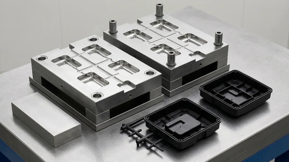
Designing high-performance plastic injection molds requires balancing upfront tooling expenditure against recurring piece-part production economics. Therefore, evaluating hot runner vs cold runner molds represents a critical architectural decision during early tooling design. Both runner architectures convey molten thermoplastic resin from the machine nozzle into individual mold cavities. However, their thermal management principles, cycle speeds, and scrap rates differ fundamentally.
Cold runner molds solidify both parts and distribution runners during every shot, requiring mechanical ejection and degating. In contrast, hot runner molds maintain molten polymer inside an electrically heated internal manifold indefinitely. Consequently, hot runner tools inject resin directly into cavity gates without producing solid plastic scrap. In this engineering evaluation, we examine thermal kinematics, gating types, and volume breakeven thresholds.
- Core Focus & DFM Scope: Actionable shop-floor engineering guidelines for Hot Runner vs Cold Runner Molds, covering material selection, geometric tolerancing, and defect prevention.
- Dimensional Tolerance Baseline: General molded/cast features hold ISO 2768-mK or ±0.05 to ±0.10 mm (±0.002″ to ±0.004″); critical post-machined datum bores achieve ±0.010 mm (±0.0004″).
- Tooling & Surface Integrity: Cavity surfaces finished from SPI A-2 mirror polish (Ra 0.05 µm / 2 µin) to VDI 3400 spark-eroded textures with mandatory 1.0°–2.5° draft angle compensation.
- Metrology & Flow Validation: Pre-tooling DFM and rheological fill simulation paired with Zeiss CMM first-article inspection (FAI) and wall-thickness ultrasonic/section verification.
- Ex-Factory Turnaround: 7 to 12 business days for vacuum cast/urethane bridge batches; 18 to 35 business days for rapid aluminum/P20/H13 tooling and T1 sample delivery (excluding 3–5 days air transit).
1. Tooling Architecture and Thermal Management Dynamics
The fundamental divide between these tooling philosophies centers on thermal zoning inside the mold base. In standard two-plate or three-plate cold runner molds, cooling channels chill the entire tool uniformly. As a result, polymer inside sprues, runners, and gates freezes simultaneously with molded components. Operators or robotic pickers must separate parts from runners before downstream packaging.
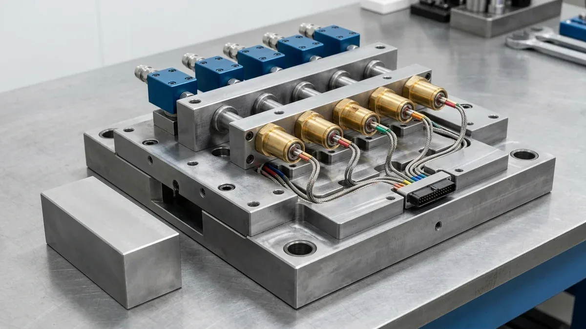
Conversely, hot runner molds incorporate an insulated internal manifold block equipped with cartridge heaters and thermocouples. Independent digital temperature controllers maintain molten polymer at precise processing temperatures up to the gate orifice. Furthermore, specialized cooling water jackets surround the heated manifold to protect surrounding tool steel plates. In shop-floor practice, thermal expansion calculations dictate manifold pocket dimensions and nozzle shut-off alignments.
2. Cycle Time Reduction and Resin Scrap Economics
In cold runner tooling, the thickest runner branch frequently dictates the minimum allowable cooling duration. Because thick runners take longer to freeze than thin part walls, overall molding cycle times increase noticeably. In contrast, hot runner molds eliminate solid runner solidification entirely. Therefore, cycle times depend strictly on part wall thickness, increasing production output by up to thirty percent.
Moreover, eliminating solid runner networks prevents massive plastic resin scrap accumulation. In multi-cavity tools producing micro-components, cold runners often outweigh the molded parts themselves. Regrinding scrap runners degrades polymer molecular weight and risks airborne contamination. Through our custom injection molding services, hot runner systems deliver zero-waste molding for expensive resins like PEEK.
The comparative engineering parameters and operational dynamics are contrasted in the table below.
| Engineering Attribute | Cold Runner Injection Molds | Hot Runner Injection Molds |
|---|---|---|
| Tooling Initial Cost | Low to moderate (Standard Cold Runner Base) | High (Heated Manifold & Nozzle Controllers) |
| Scrap Generation | Solid sprues and runners every cycle | Zero runner scrap; 100% material efficiency |
| Cooling Cycle Speed | Slower (governed by runner thickness) | Faster (governed only by part nominal wall) |
| Color Change Agility | Fast and straightforward (purge in barrel) | Slow (requires extensive manifold purging) |
| Maintenance Complexity | Simple; standard mechanical maintenance | Complex; electrical heaters, valve pins, seals |
3. Gate Types: Edge, Sub-Gates, and Valve Gate Drops
Gate vestige aesthetics and cavity entry physics differ substantially across these tooling systems. Cold runner molds utilize simple edge gates, sub-surface tunnel gates, or cashew gates that shear cleanly during mold opening. Conversely, hot runner molds deploy thermal direct-sprue gates or advanced pneumatic valve gates. Valve gates utilize internal carbide pins that retract to allow resin flow and extend forward to shut off mechanically.
Consequently, valve-gated hot runner tools leave virtually invisible, mirror-flat gate vestiges on cosmetic surfaces. From an engineering perspective, sequential valve gating allows tooling engineers to open individual gates progressively as the melt front advances. This controlled sequence eliminates hazardous weld lines on large automotive fascias and medical housing shells. For low-volume prototype verification, AS Prototypes also utilizes polyurethane vacuum casting before committing to production tooling.
4. Cost Economics and Volume Breakeven Thresholds
The decision to invest in hot runner tooling hinges directly on total production volume and material unit cost. Cold runner tooling represents the most sensible pathway for production volumes under twenty thousand units. The lower upfront mold fabrication cost offsets minor runner scrap losses and slightly longer cycle times. In addition, cold runners excel when molding runs require frequent resin color changes.
However, when part volumes exceed one hundred thousand units, hot runner systems deliver dramatic cumulative cost savings. Shorter cycle times maximize machine press hourly output, lowering overhead allocation per part. Furthermore, saving tens of thousands of pounds of expensive virgin resin rapidly amortizes manifold capital costs. AS Prototypes provides comprehensive mold flow simulations and financial breakeven analyses to guide your tooling procurement.
The volume breakeven matrix across common production scenarios is summarized in the table below.
| Annual Production Volume | Recommended Runner Strategy | Primary Economic Justification | Typical Tooling Payback Period |
|---|---|---|---|
| 1,000 to 10,000 Parts | Two-plate cold runner tooling | Lowest initial tooling cost; fast mold build lead time | Immediate cost efficiency |
| 10,000 to 50,000 Parts | Three-plate cold runner or cold sub-gate | Automatic part/runner separation without manifold cost | Balanced prototype/pilot scaling |
| 50,000 to 200,000 Parts | Semi-hot runner (hot sprue to cold runner) | Reduced sprue scrap with moderate tooling investment | 6 to 12 months payback |
| 200,000+ Parts (High Volume) | Full hot runner with valve gates | Maximum cycle speed, zero scrap, automated packing | Under 4 months payback |
| Expensive Resins (PEEK / PPS) | Full hot runner even at medium volume | Eliminating high-cost material waste amortizes tool quickly | 3 to 6 months payback |
Why Do Hot Runner Vs Cold Runner Molds Projects Experience Dimensional Warpage or Flash, and How Do You Prevent It?
Managing Hot Runner vs Cold Runner Molds successfully requires balancing volumetric shrinkage, cavity clamping pressure, and thermal dissipation across uneven wall cross-sections. While uniform walls of 1.5 to 3.0 mm (0.060″ to 0.118″) stabilize flow fronts within ±0.05 mm (±0.002″), abrupt rib-to-wall transitions exceeding a 0.6:1 ratio induce localized sink marks, internal voids, and residual warpage.
Shop-Floor Quantitative Derivation: Clamping Force, Shrinkage & Thermal Cooling Balance
In our Shenzhen tooling and molding engineering practice, preventing parting-line flash and dimensional drift in Hot Runner vs Cold Runner Molds starts with exact clamping tonnage and linear shrinkage compensation before steel or aluminum blocks are cut. Consider a structural housing with a projected cavity area Aproj = 140 cm² (21.7 in²) molded at an internal cavity pressure Pcav = 45 MPa (6,525 psi):
Fclamp = Aproj × Pcav × Sf = 140 cm² × 0.45 kN/cm² × 1.20 = 75.6 tonnes (83.3 US tons)
Simultaneously, tooling cavity dimensions (Dcavity) must compensate for isotropic or anisotropic material shrinkage (S).
For a nominal 120.00 mm (4.7244″) datum spacing with a semi-crystalline or alloy shrinkage factor of S = 1.6% (0.016 mm/mm), the machined cavity steel dimension is calculated as Dcavity = Dnom × (1 + S) = 120.00 × 1.016 = 121.92 mm (4.8000″). To lock critical bearing bores or sealing faces within ±0.010 mm (±0.0004″), we leave a 0.40 mm (0.016″) stock allowance for post-molding 3-axis and 4-axis CNC finish milling.
Step-by-Step Shop-Floor Execution & Quality Protocol
To bridge CAD intent with repeatable shop-floor delivery, our engineering team enforces a four-stage execution workflow across every prototype and low-volume production batch:
- Step 1: Rheological Flow & Wall-Thickness DFM Audit: Analyze 3D CAD geometry (STEP/IGES) to verify uniform wall sections, apply 1.0° to 2.5° draft angles per VDI 3400 / SPI texture depth, and position gates away from cosmetic or high-stress zones.
- Step 2: Precision Cavity Machining & Venting Calibration: Machine P20, H13, S136, or 7075-T651 tooling inserts via high-speed CNC milling and Wire/Sinker EDM, grinding perimeter gas vents to 0.015–0.030 mm (0.0006″–0.0012″) depth to evacuate trapped air without flash.
- Step 3: Thermal Stabilization & Scientific Process Windowing: Stabilize mold tool temperature via turbulent conformal/baffle cooling channels (Reynolds number Re > 4,000) and decouple fill, pack, and hold stages to eliminate weld lines and internal porosity.
- Step 4: T1 First-Article Zeiss CMM & Section Verification: Inspect T1 shots after 24-hour thermal conditioning at 20°C (68°F) using Zeiss CMM probing and optical comparator overlays against ISO 2768-mK and drawing GD&T callouts.
Shop-Floor Defect Troubleshooting & Corrective Action Matrix
When evaluating part geometry during pre-production DFM review, our manufacturing engineers screen for the following failure modes and apply proven corrective controls:
| Defect / Symptom | Physical Root Cause | Shop-Floor Corrective Action | Recommended DFM Spec Limit |
|---|---|---|---|
| Parting-Line Flash / Burrs | Insufficient clamp tonnage, excessive injection velocity, or vent depth exceeding 0.04 mm (0.0016″) | Increase clamp safety factor to 1.25×, switch from velocity-to-pressure transfer at 98% fill, and lap parting faces to ≤0.010 mm (≤0.0004″) shutoff. | Flash ≤ 0.05 mm (0.002″) |
| Localized Sink Marks & Voids | Rib-to-wall thickness ratio exceeding 60% causing core thermal contraction after skin freeze | Coring out thick bosses, reducing rib root thickness to 50%–60% of nominal wall, and extending packing pressure until gate freeze-off. | Rib root = 0.5–0.6 × twall |
| Flow Weld / Knit Line Weakness | Converging melt/flow fronts cooling below fusion threshold around cored holes or inserts | Raise melt and mold surface temperatures by 15°C–25°C (27°F–45°F), add overflow wells at knit zones, and relocate gate entry vectors. | Tensile retention ≥ 85% |
| Post-Ejection Warpage & Twist | Differential cooling across asymmetric cavity halves or fiber orientation anisotropy | Balance core/cavity coolant delta within ΔT ≤ 5°C (9°F), anneal stressed parts in precision cooling jigs, and post-machine critical datums. | Flatness ≤ 0.10 mm / 100 mm |
Engineering Trade-Offs: When NOT to Over-Specify
When to Avoid This Process (Engineering Limitations): Do not specify dedicated hard tooling or molding workflows when unit quantities are under 10 pieces and the design geometry is still undergoing weekly functional revisions. In early-stage validation where upfront tooling amortization and 18 to 35 business days of tool fabrication delay testing, direct high-speed 3-axis and 4-axis CNC machining from solid engineering billet or polyurethane vacuum casting (4 to 12 business days ex-factory) delivers superior agility with zero steel modification risk.
🔗 Related Tooling & Molding Engineering Benchmarks:
Optimizing Hot Runner vs Cold Runner Molds requires coordinating cavity thermal management, surface texture draft angles, and bridge production pathways. Explore our in-depth guides on Conformal Cooling vs. Conventional Cooling Channels to cut cycle times by 20%–35%, Preventing Flow Marks & Cosmetic Molding Defects, and Polyurethane Vacuum Casting for 10–50 Unit Bridge Runs.
Cold runner molds are ideal for runs below 20,000 parts. Furthermore, they excel with frequent color changes and heat-sensitive polymers. They feature significantly lower upfront tooling costs and simpler maintenance. At AS Prototypes, our engineering team validates these parameters against ISO 2768-mK general tolerances (with critical mating features held to ±0.010 mm / ±0.0004″) and provides 24-hour DFM feedback.
In cold runner molds, the thick runner branch dictates cooling time. Hot runner molds keep runners liquid in a heated manifold, meaning cooling duration depends solely on part wall thickness. At AS Prototypes, our engineering team validates these parameters against ISO 2768-mK general tolerances (with critical mating features held to ±0.010 mm / ±0.0004″) and provides 24-hour DFM feedback.
Valve gates utilize mechanical pins to close gate apertures flush with the part cavity wall. This produces an imperceptible gate vestige while preventing drooling, stringing, and cosmetic surface sink marks. At AS Prototypes, our engineering team validates these parameters against ISO 2768-mK general tolerances (with critical mating features held to ±0.010 mm / ±0.0004″) and provides 24-hour DFM feedback.