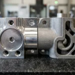
Executive Summary & Engineering Scope
In precision hardware development, an elegant 3D CAD model is only as viable as its underlying manufacturability. Empirical manufacturing data demonstrates that 70% to 80% of a hardware product’s ultimate unit manufacturing cost is irrevocably locked in during initial geometric CAD release. A disconnect between nominal digital solid modeling and physical shop-floor dynamics—such as rotating milling cutter kinematics, sheet metal plastic yield limits, polymer cooling contraction, and thermal residual stress curl—routinely leads to 30% to 70% cost inflation, excessive spindle run times, and avoidable tooling modifications.
This technical whitepaper provides a comprehensive, multi-process engineering reference for Design for Manufacturing (DFM) and Design for Assembly (DFA). Written by our applications engineering team at our in-house precision CNC machining and rapid prototyping facility, this guide establishes governing physical equations, empirical geometric thresholds, tolerance cost multiplier curves, and a 15-point pre-flight checklist to help engineering teams eliminate manufacturing bottlenecks before releasing drawings to production.
Whitepaper Index & Quick Navigation
1. The AS Prototypes 5-Stage Engineering DFM Review Workflow
When engineering teams upload 3D CAD models to our production engineering portal, our team does not simply run an automated script; our senior manufacturing engineers perform a comprehensive, hands-on 5-stage DFM review before cutting raw stock or machining tooling steel:
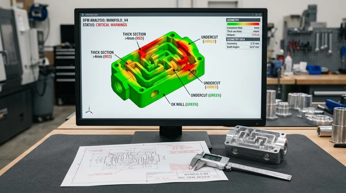
Geometric Ingestion & Heatmap Audit
Automated digital scan of 3D CAD geometry (STEP / IGES) evaluating wall thickness heatmaps, draft angles, deep narrow pockets, and undercut features.
Toolpath & Kinematics Feasibility
Tool reach simulation, cutter diameter-to-depth ratios (L/D), standard tooling availability, and multi-axis fixture clearance checks in CAM.
Tolerance & Datum Alignment
Reviewing drawing blueprints to align GD&T datum reference frames (A, B, C) with assembly kinematics and eliminating cost-inflating over-tolerancing.
24-Hour DFM Redline Report
Delivering annotated 3D CAD screenshots with recommended corner radius enlargements, coring profiles, and transparent cost-reduction proposals.
Production & FAI Verification
First article inspection (FAI) and multi-axis Zeiss CMM metrology verification executed on demand, ensuring zero-defect series production.
2. The Fundamental Economics & The “Rule of Ten” in DFM
The primary economic driver of Design for Manufacturing is the classic manufacturing “Rule of Ten”: resolving a design oversight costs approximately $1 during initial 3D CAD modeling, $10 during rapid prototype machining, $100 during production mold or fixture tooling fabrication, and $1,000 to $10,000+ once parts are deployed into final assembly or customer hands. Conducting rigorous DFM reviews before releasing drawings to the shop floor locks in 70% to 80% of final product manufacturing costs before the first chip is cut.
The Tolerance vs. Cost Multiplier Curve
One of the most common design pitfalls identified during upfront DFM analysis is blanket over-tolerancing. Specifying unnecessarily tight tolerances across non-critical clearance features exponentially inflates machine cycle times, tool wear, and scrap rates:
| Tolerance Precision Tier | Dimensional Threshold | Machining & Inspection Requirements | Relative Cost Factor |
|---|---|---|---|
| Standard Commercial | ISO 2768-mK (±0.10 mm to ±0.20 mm) | Standard high-speed roughing and finishing toolpaths; standard shop-floor micrometer/caliper checks. | 1.0× (Baseline) |
| Fine Machining | ISO 2768-fH (±0.020 mm to ±0.050 mm) | Dedicated spring finishing passes; thermal stabilization of machine spindle and coolant; digital bore micrometer checks. | 1.3× to 1.5× |
| Precision Tooling | ±0.010 mm (±0.0004 in) | Micro-grain solid carbide cutters; slow finishing feed rates; in-process touch probing; climate-controlled CMM metrology verification. | 2.0× to 2.5× |
| Ultra-Precision Ground / EDM | ±0.005 mm (±0.0002 in) | Secondary precision surface grinding or Sodick wire EDM; multi-hour machine warm-up; 100% CMM coordinate verification. | 3.5× to 5.0× |
3. Core DFM Rules for Precision CNC Machining
Subtractive CNC machining removes material using rotating cutting tools mounted in rigid spindles. Observing proven machining DFM rules avoids excessive spindle run times, premature tool wear, and expensive secondary benching operations:
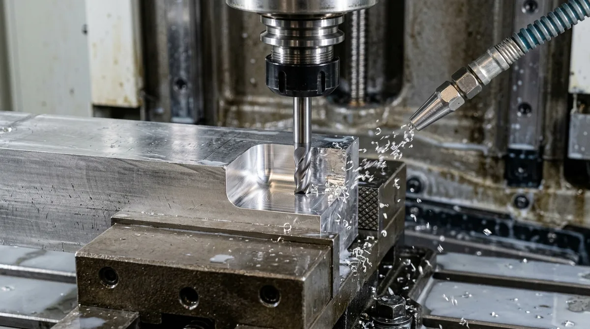
1. Internal Vertical Corner Radii: Avoid Sharp 90° Corners
Because milling cutters rotate about a central axis, an end mill cannot physically cut a sharp 90° internal vertical corner. Requesting sharp internal vertical corners forces the machine shop to deploy secondary sinker EDM (Electrical Discharge Machining) using custom-machined copper or graphite electrodes, doubling part cost and extending lead times.
Engineering Rule: Always specify an inside corner radius at least 10% to 15% larger than the intended milling cutter radius:
Rcorner ≥ 1.15 × (Dcutter / 2)
For example, if using a standard Ø6.0 mm end mill (3.0 mm radius), specify an internal corner radius of R ≥ 3.5 mm. This enables the machine toolpath to execute a continuous, smooth circular arc through the corner rather than forcing the tool to decelerate to a complete stop, eliminating cutter chatter, surface gouging, and tool breakage.
When a square or rectangular mating component (such as an electronics circuit board or battery pack) must seat completely flush against the pocket floor and corners, do not specify sharp corners. Instead, design a “dog-bone” or “T-bone” corner relief. By drilling or interpolating a small circular undercut slightly past the corner vertex, the square mating part drops in effortlessly without requiring expensive sinker EDM passes.
2. Cavity Depth-to-Diameter Ratio: Euler-Bernoulli Tool Deflection Physics
Cutting tool deflection follows Euler-Bernoulli cantilever beam mechanics. A rotating end mill subject to radial cutting force F deflects at its tip according to the classical equation:
δ = (F × L³) / (3 × E × I) | where I = (π × D⁴) / 64 ⇒ δ ∝ L³ / D⁴
Because deflection δ scales with the cube of unsupported overhang length (L³) and inversely with the fourth power of tool diameter (D⁴), doubling tool overhang length increases tool deflection by 2³ = 8×, while cutting cutter diameter in half increases deflection by 2⁴ = 16×! Excessive deflection induces severe acoustic chatter, tapered pocket walls, poor surface finish (Ra > 3.2 μm), and premature micro-carbide tooth chipping.
Engineering Rule: Restrict pocket depths to a maximum depth-to-width ratio of L/D ≤ 4:1 for aluminum alloys and L/D ≤ 3:1 for stainless steels and titanium. If deep cavities are essential for internal fluid routing or housing volume, incorporate stepped sidewalls with a 1° to 2° draft angle so that larger-diameter, high-rigidity toolholders can reach lower floor depths without clearance collisions.
3. Wall Thickness & Feature Aspect Ratios
Thin vertical walls deflect elastically away from cutter flutes under cutting pressures. This deflection leads to dimensional taper, acoustic chatter marks, and severe residual stress warpage when the part is released from the vise.
Engineering Rule: Maintain a minimum wall thickness of T ≥ 1.0 mm (preferably ≥ 1.5 mm) for aluminum alloys. For tough materials like 304/316L stainless steel, titanium Ti-6Al-4V, and flexible engineering plastics like POM or nylon, specify wall thicknesses of T ≥ 1.5 mm to 2.0 mm. Avoid tall, unsupported thin ribs exceeding a height-to-thickness ratio of 8:1.
4. Multi-Axis Consolidation & Setup Minimization
Every time an operator unclamps a workpiece, rotates it to a new orientation, and reclamps it into a soft jaw or fixture, machine setup overhead increases and datum stacking errors multiply across coordinate axes.
Engineering Rule: Design components so that all critical precision features can be accessed from as few directions as possible. For complex prismatic parts with angled bores and 3D compound surfaces, designing for 5-axis simultaneous CNC machining allows five faces to be contoured in a single clamping setup, guaranteeing true positional tolerances down to ±0.010 mm.
5. Thread Depth & Blind Hole Design
Specifying excessively deep threaded holes does not increase mechanical fastening strength; research demonstrates that the first four to six threads carry over 80% of the total tensile clamping load. Tapping deep blind holes dramatically increases the risk of tap seizure and broken tools embedded in near-finished workpieces.
Engineering Rule: Maintain thread engagement length between 1.5 × D and 2.5 × D (where D is nominal screw diameter). For blind tapped holes, always extend the drilled pilot hole depth by at least 0.5 × D beyond the last full thread to provide adequate chip clearance and tap lead-in chamfer runout.
Upload your STEP / IGES files for an instant DFM manufacturability check and rapid quote within 24 hours.
4. Core DFM Rules for Precision Sheet Metal Fabrication
In our in-house precision sheet metal fabrication operations, flat laser-cut sheet blanks undergo localized plastic deformation under CNC press brake tonnage. Adhering to metal-forming mechanics prevents edge tearing, hole elongation, and dimensional drift:
1. Standardize Inside Bend Radii & Neutral Axis K-Factor Mechanics
When multiple bends on a single sheet metal part call for different inside bend radii, press brake operators must stop production, remove the upper punch and lower V-die, and re-tool between steps, drastically increasing manufacturing labor costs. Furthermore, sheet metal plastic deformation causes the material’s neutral axis to shift inward toward the inner bend radius:
BA = (π / 180) × θ × (Rinside + K × T)
where K = t / T represents neutral axis shift (K ≈ 0.33 for copper, 0.38 for 5052-H32 aluminum, 0.44 for mild steel)
Engineering Rule: Standardize on a single inside bend radius across the entire part, typically Rinside = 1.0 × T for mild steel and 5052 aluminum, or Rinside = 1.5 × T to 2.0 × T for hardened 6061-T6 aluminum to prevent outer fiber cracking. This allows continuous multi-bend forming on a single press brake setup.
2. Prevent Hole Deformation Near Bend Lines
During sheet metal bending, the material along the bend zone undergoes intense plastic deformation: tensile stretching along the outer radius and compressive flow along the inner radius. If a round mounting hole is placed within this deformation zone, it deforms into an unsightly, out-of-round oval that binds mounting hardware.
Engineering Rule: Ensure the distance from the outer edge of any hole or cutout to the tangent of the bend line complies with:
Dhole-to-bend ≥ 2.5 × T + Rinside
If mechanical clearance requires a hole closer to the bend line, extend the cutout through the bend zone as a relief slot prior to bending.
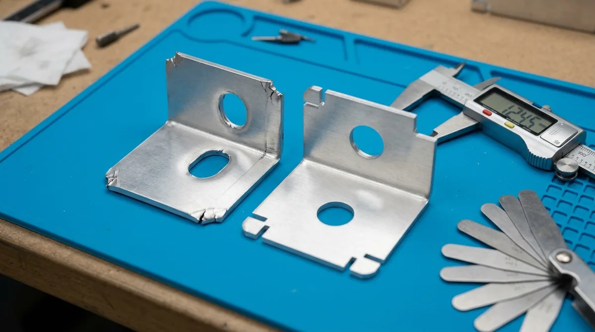
3. Laser-Cut Rectangular Bend Relief Notches
When a bent flange terminates adjacent to a flat planar edge or another perpendicular flange, severe shear tearing occurs at the transition corner unless relief geometry is provided.
Engineering Rule: Always incorporate laser-cut rectangular bend relief notches at every flange intersection. The relief notch width must be at least equal to sheet thickness (W ≥ T), and its depth must extend past the tangent bend line (L ≥ Rinside + T). This isolates plastic strain, resulting in clean, crack-free 90° corner seams.
4. Minimum Flange Height for Tooling Seating
Forming an excessively short flange is physically impossible on a standard press brake because the flange cannot span across the opening of the lower V-die before the punch engages, resulting in slip and out-of-tolerance bend angles.
Engineering Rule: Design flange heights to be at least Hmin ≥ 4 × T + Rinside. This ensures the flange rests securely against both shoulders of the lower die throughout the bending stroke.
Cold-rolled sheet metal exhibits directional grain alignment along its coil rolling direction. Bending sheet metal parallel to the rolling grain induces micro-fissuring and structural fracture along the outer bend radius. Whenever nesting laser-cut flat patterns, orient major bend lines at a 45° to 90° angle relative to the material grain direction to maximize structural yield strength.
5. Core DFM Rules for Plastic Injection Molding & Rapid Tooling
When transitioning plastic parts from prototypes into injection molding tooling and series production, polymer melt thermodynamics and mold kinematics govern part quality. Proper DFM eliminates cosmetic sink marks, flow voids, and mold release sticking:
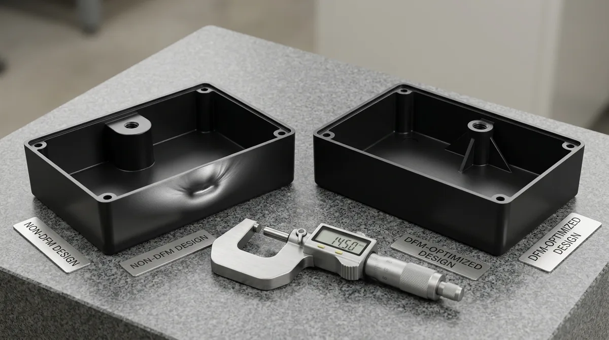
1. Uniform Wall Thickness & Volumetric Thermal Contraction
Thermoplastic resins shrink volumetrically as they cool from melt temperature (~200°C to 300°C) down to mold temperature according to volumetric thermal contraction dynamics:
ΔV = V₀ × βv × ΔT | where βv is volumetric thermal expansion coefficient
In areas with thick, solid plastic masses (such as solid screw bosses or thick wall junctions), the exterior skin solidifies first while the molten internal core continues to cool and contract. This differential contraction pulls the outer skin inward, forming an unsightly surface depression (sink mark) or an internal vacuum void that weakens structural load capacity.
Engineering Rule: Maintain uniform nominal wall thickness throughout the part (typically 1.5 mm to 3.0 mm for technical enclosures). Transition thick-to-thin sections gradually with a 3:1 chamfer taper. Always core out thick screw bosses from the rear, ensuring the boss wall thickness is restricted to:
Tboss = 0.50 to 0.60 × Tnominal wall
Support the cored boss with three or four thin gusset ribs to achieve high torsional pull-out strength without creating cosmetic sink defects on the exterior cosmetic surface.
Never design internal reinforcing ribs with the same thickness as the nominal outer wall. For high-shrinkage crystalline polymers (POM, PP, PA66), rib base thickness must not exceed 40% to 50% of the nominal wall. For amorphous resins (ABS, PC), rib base thickness must not exceed 60%. Violating this rule guarantees visible sink shadow lines along cosmetic Class-A surfaces that cannot be concealed by mold texturing.
2. Adequate Draft Angles for Clean Part Ejection
As molten plastic solidifies inside the mold cavity, it contracts onto the mold core steel. Vertical walls with 0° draft generate massive frictional drag against the core during mold opening, causing ejector pin punch-through, severe scuff marks, and part distortion.
Engineering Rule: Apply a minimum draft angle of 1.0° to 2.0° per side to all vertical surfaces parallel to the mold draw direction. For deep structural ribs or narrow shut-offs, provide at least 0.5° minimum. For cosmetic surfaces requiring textured finishes (such as Mold-Tech or VDI spark erosion textures), add an additional 1.0° of draft for every 0.020 mm (0.0008 in) of texture depth to prevent ejection drag tearing.
3. Structural Rib Geometry & Base Fillets
Designing excessively thick reinforcing ribs generates severe sink marks along the opposite exterior surface, while overly thin ribs fail to fill completely during injection filling.
Engineering Rule: Size rib base thickness to Trib ≤ 0.50 × Twall for high-shrinkage resins (POM, PP, PA66) and Trib ≤ 0.60 × Twall for low-shrinkage amorphous resins (ABS, PC). Limit rib height to Hrib ≤ 3.0 × Twall, and apply a base fillet radius of R ≥ 0.25 to 0.50 × Twall to distribute mechanical stresses without concentrating mass.
6. Core DFM Rules for Additive Manufacturing & Hybrid CNC Finishing
Industrial additive manufacturing—including Direct Metal Laser Sintering (DMLS / LPBF), Selective Laser Sintering (SLS), and Stereolithography (SLA)—unlocks unprecedented geometric freedom. However, high-yield AM production still demands rigorous DFM to prevent thermal residual stress curling and recoater blade crashes:
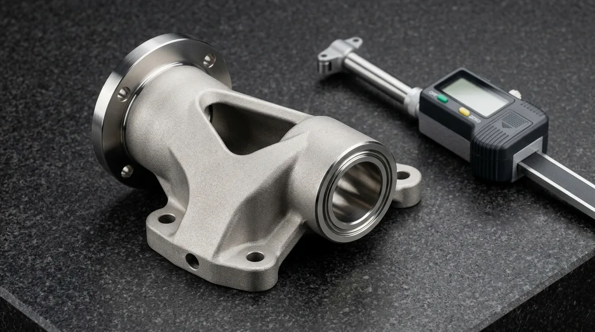
1. Self-Supporting Overhang Angles
In metal powder bed fusion (DMLS / SLM), printing downward-facing angles shallower than 45° from horizontal requires sacrificial support structures to conduct away laser heat and resist thermal curling. Removing internal metal supports is labor-intensive and leaves rough scarred surfaces.
Engineering Rule: Design all overhang angles, fluid channels, and teardrop internal holes with angles of ≥ 45° from the horizontal build plane. For internal horizontal fluid channels, utilize self-supporting diamond or inverted teardrop cross-sections to eliminate internal supports entirely.
2. Powder Evacuation Ports for Hollow Geometries
Enclosing hollow chambers or lightweight lattice cores without drainage traps heavy, un-sintered raw alloy powder inside the part, adding dead weight and creating outgassing hazards.
Engineering Rule: Provide at least two powder evacuation drain ports with a minimum diameter of Ø ≥ 4.0 mm (preferably ≥ 6.0 mm) located at opposite ends of the cavity to allow pressurized air clearing and ultrasonic solvent flushing.
3. Hybrid Additive-Subtractive Machining Allowances
While additive manufacturing excels at producing complex organic brackets and conformal cooling lines, as-printed surface roughness (typically Ra 4.0 μm to 8.0 μm) and dimensional tolerances (±0.10 mm to ±0.20 mm) cannot seat precision bearings or seal high-pressure hydraulic O-rings.
Engineering Rule: Design critical interface features (bearing bores, sealing faces, datum locating holes) with an extra 0.5 mm to 1.0 mm of sacrificial machining stock. After thermal stress-relief annealing, these critical features are post-machined via secondary 5-axis CNC finishing to achieve Ra 0.4 μm surface roughness and precise ±0.010 mm tolerances.
7. Design for Assembly (DFA) & GD&T Tolerance Synergies
Design for Manufacturing (DFM) must always be paired with Design for Assembly (DFA). A component that is economical to machine but labor-intensive or prone to error during manual assembly inflates total production costs:
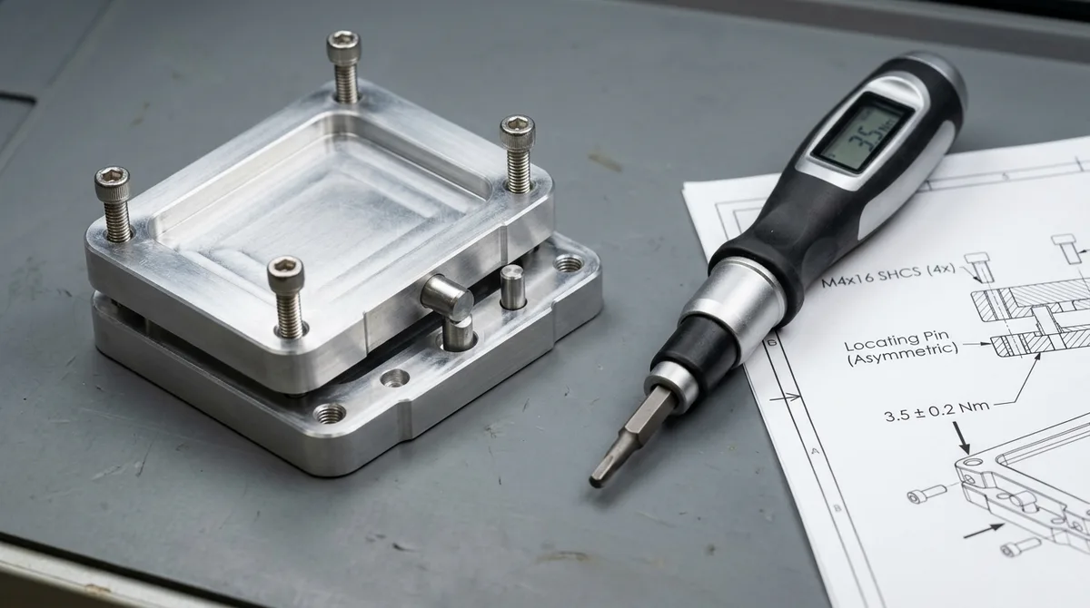
1. Poka-Yoke (Mistake-Proof) Geometric Keys
Symmetrical parts that must be installed in a specific internal orientation inevitably get assembled backwards on rapid production lines, leading to electrical shorts or mechanical binding.
Engineering Rule: Integrate asymmetric locating dowel pins, offset mounting screw patterns, or polarized indexing tabs. Ensure that two mating halves can physically mate in only one correct orientation.
2. Monolithic Part Consolidation
Traditional multi-piece assemblies joined by welded joints, sheet metal brackets, and dozens of threaded fasteners introduce extensive tolerance stack-up and manual assembly labor.
Engineering Rule: Consolidate multi-piece assemblies into single monolithic structural components utilizing 5-axis CNC machining or metal 3D printing. Eliminating fasteners removes joint compliance, reduces assembly inspection time, and enhances structural rigidity.
3. Fastener Standardization Across the Subassembly
Utilizing a patchwork of M2.5, M3, M4, and M5 screws across a single device forces technicians to switch torque tools continuously, increasing assembly cycle times and risking cross-threading.
Engineering Rule: Standardize on a single fastener thread and drive standard across the entire subassembly (e.g., standardizing on M4×16 mm socket head cap screws with standard hex drive). This allows the assembly cell to operate with a single calibrated torque driver preset to specified torque ratings (e.g., 3.5 ± 0.2 Nm).
8. Quality Control, GD&T & Precision Metrology Verification
A rigorous DFM review also establishes a practical quality control inspection roadmap. Over-tolerancing non-critical clearance holes increases inspection costs without adding functional value:
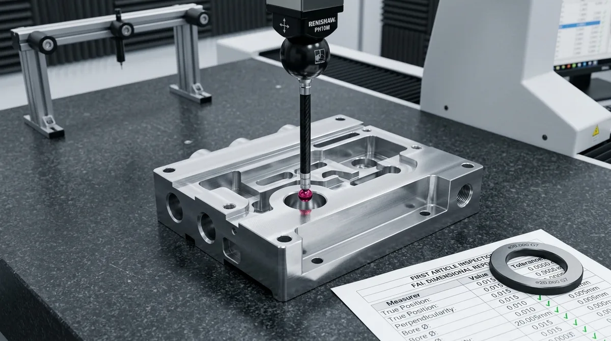
1. Establish Functional Datum Reference Frames & MMC Bonus Tolerance (ASME Y14.5)
Rather than placing loose ±0.02 mm linear tolerances between unrelated features, establish clear Primary (A), Secondary (B), and Tertiary (C) datums based on how the component mounts in the final assembly. Applying Maximum Material Condition (MMC) modifiers provides shop-floor machinists with allowable bonus tolerance as hole sizes depart from MMC:
Bonus Tolerance = |Actual Produced Hole Diameter − MMC Minimum Hole Diameter|
2. Standard Baseline Tolerancing (ISO 2768)
Unless specifically noted on engineering blueprints, our precision CNC machining operations default to ISO 2768-mK (standard precision) or ISO 2768-fH (fine precision ±0.010 mm to ±0.020 mm for critical metal mating features). Engineering plastics follow ISO 2768-mK to accommodate natural thermal and hygroscopic expansion.
3. Metrology Verification & Traceable FAI Reports
To verify critical geometric tolerances (perpendicularity, true position, concentricity, and bore roundness), our metrology inspection laboratory deploys multi-axis Zeiss coordinate measuring machines (CMM) and digital optical measuring systems. Comprehensive First Article Inspection (FAI) dimensional reports and traceable Mill Test Reports (MTR) are available upon request to validate complete blueprint compliance.
9. Engineering Case Study: Aerospace Hydraulic Manifold DFM Optimization
To demonstrate the quantifiable impact of upfront DFM engineering, consider a recent production optimization conducted by our engineering team on an aerospace avionics hydraulic manifold machined from 6061-T6 aluminum:
Initial Customer CAD Challenges (Non-DFM)
- Six internal pocket corners specified sharp 90° vertical vertices (R = 0.5 mm), requiring 4 copper sinker EDM electrode burns.
- Cavity depth was 45 mm with a Ø6.0 mm cutter reach (L/D = 7.5:1), creating severe acoustic chatter and tapered floor corners.
- Blanket ±0.010 mm linear tolerance across 16 non-critical M3 mounting clearance holes.
- Patchwork of four fastener sizes (M2.5, M3, M4, M5) across a 110 mm compact chassis.
AS Prototypes DFM Interventions
- Enlarged inside vertical corner radii to R = 3.5 mm, allowing continuous circular arc milling with standard Ø6.0 mm tools.
- Added 1.5° pocket sidewall draft, enabling short, rigid shrink-fit toolholders to finish floor depths without chatter.
- Relaxed non-critical clearance hole tolerances to ISO 2768-mK; applied ASME Y14.5 composite true-position datums to valve spools.
- Unified all chassis fasteners to standardized M4×16 mm socket head hardware.
| Key Performance Metric | Initial Non-DFM CAD | DFM Optimized Production | Engineering & Cost ROI |
|---|---|---|---|
| Spindle Machining Cycle Time | 114 minutes / part | 62 minutes / part | -45.6% Spindle Time |
| Sinker EDM Electrode Tooling | 4 Custom Copper Electrodes (High Tooling Overhead) | 0 (100% eliminated via R3.5mm radii) | Tooling Surcharge Eliminated |
| Clamping & Setup Iterations | 3 setups (Standard soft-jaw vise) | 1 setup (5-Axis dovetail fixture) | -66% Setup Overhead |
| Shop-Floor Scrap Rate (100-pc batch) | 6.8% (Wall chatter & taper) | 0.2% (100% first-pass CMM yield) | -97% Scrap Reduction |
| Relative Unit Production Cost | 1.60x Baseline Cost Index | 1.00x Optimized Index | -37.4% Net Cost Reduction |
10. The 15-Point Pre-Flight DFM Checklist for Hardware Engineers
Before releasing your 3D CAD models and blueprints for prototype quotation or production release, verify your design against our shop-floor engineering checklist:
| No. | Engineering Checkpoint | Target Process | Golden DFM Design Rule | Failure Avoidance Objective |
|---|---|---|---|---|
| 01 | Internal Corner Radii | CNC Milling | R ≥ 1.15 × (Tool Radius) | Prevents cutter chatter and costly Sinker EDM |
| 02 | Pocket Depth Ratio | CNC Milling | L/D ≤ 4:1 (Al) / 3:1 (Steel) | Prevents tool deflection and tapered cavity walls |
| 03 | Minimum Wall Thickness | CNC Machining | T ≥ 1.0 mm (Al) / 1.5 mm (Plastics) | Eliminates chatter and vibration warping |
| 04 | Blind Thread Engagement | CNC Tapping | 1.5D to 2.5D; extra 0.5D pilot relief | Avoids bottoming out and tap breakage |
| 05 | Flush Corner Relief | CNC Milling | Dog-bone or T-bone undercuts | Allows rectangular parts to seat completely flush |
| 06 | Bend Relief Notches | Sheet Metal | Width W ≥ T, Depth L ≥ R + T | Eliminates edge tearing at flange transitions |
| 07 | Hole-to-Bend Clearance | Sheet Metal | D ≥ 2.5T + R | Prevents oval distortion during plastic bending |
| 08 | Uniform Bend Radii | Sheet Metal | R = 1.0T standardized across part | Eliminates mid-production press brake tool swaps |
| 09 | Screw Boss Coring | Injection Molding | T_boss = 0.50 to 0.60T_nominal | Eliminates cosmetic sink mark craters and voids |
| 10 | Draft Angle Allocation | Injection Molding | 1.0° to 2.0° per side; +1° per 0.02 mm texture | Guarantees clean mold ejection without drag marks |
| 11 | Rib-to-Wall Ratio | Injection Molding | T_rib ≤ 0.50T_wall; Height ≤ 3T_wall | Prevents sink marks along cosmetic Class-A faces |
| 12 | AM Overhang Self-Support | Metal 3D Printing | Overhang angle ≥ 45° from horizontal | Eliminates internal support removal and scarring |
| 13 | Powder Escape Ports | DMLS / SLS | Two ports Ø ≥ 4.0 mm at opposite ends | Allows total evacuation of raw unsintered powder |
| 14 | Poka-Yoke Assembly Keys | Assembly (DFA) | Asymmetric dowels, offset hole patterns | Makes backwards 180° assembly physically impossible |
| 15 | Fastener Standardization | Assembly (DFA) | Unify hardware to single thread (e.g. M4) | Eliminates torque tool switching on assembly line |
11. Engineering Comparison Matrix: DFM Guidelines Across Key Processes
The table below summarizes critical DFM constraints, recommended geometric thresholds, common non-compliance failure modes, and production cost multipliers across major manufacturing disciplines:
| Manufacturing Process | Core DFM Geometric Rules | Standard Engineering Thresholds | Non-Compliance Failure Mode | Cost Impact of Violation |
|---|---|---|---|---|
| CNC Milling & Turning | Generous internal corner radii; limit pocket depth; standardize tooling; minimize setups | Corner radius R ≥ 1.15 × (D_tool / 2); Pocket depth L/D ≤ 4:1; Wall thickness T ≥ 1.0 mm (Al) / 1.5 mm (Steel) | Severe tool chatter, wall taper, tool deflection, cutter breakage | Forces secondary Sinker EDM or micro-tool passes (2× to 5× cost surge) |
| Sheet Metal Bending | Standardize inside bend radii; safe hole-to-bend setback; laser-cut bend reliefs | Inside radius R = 1.0T; Hole distance D ≥ 2.5T + R; Relief notch width W ≥ T, length L ≥ R + T | Outer bend fiber cracking, distorted oval holes, torn corner flanges | Scrapped parts, manual re-drilling, dedicated press brake tooling |
| Plastic Injection Molding | Uniform nominal wall thickness; core out thick bosses; draft angles on vertical walls | Nominal wall 1.5–3.0 mm; Boss wall T_boss = 0.50–0.60T_wall; Draft angle 1°–2° per side; Rib thickness ≤ 0.5T_wall | Cosmetic sink mark craters, thermal cooling warpage, vacuum drag scuffing | Costly tool steel weld modifications or permanent aesthetic defects |
| Additive Metal AM (DMLS/SLM) | Self-supporting overhang angles; powder drain evacuation holes; hybrid CNC stock | Overhang angle ≥ 45° from horizontal; Drain hole Ø ≥ 4.0 mm; CNC finish allowance 0.5–1.0 mm | Recoater blade crashes, trapped powder dead weight, thermal residual stress curl | Extensive manual EDM/grinding support removal or failed 24h build cycles |
| Polyurethane Vacuum Casting | Uniform wall sections; compensate for silicone shrinkage; draft deep features | Wall thickness 1.5–3.5 mm; Silicone shrinkage factor 0.25%–0.35%; Draft ≥ 0.5° | Premature silicone mold tearout, bubble voids, out-of-spec dimensions | Shortened mold tool life (dropping from 25 shots to 10 shots), frequent remolds |
12. Frequently Asked Questions
All critical geometric tolerances—including true position, planar runout, perpendicularity, and surface profile—are verified in our climate-controlled metrology laboratory using calibrated Zeiss multi-axis coordinate measuring machines (CMM) and digital optical measuring systems. Comprehensive First Article Inspection (FAI) reports and CMM metrology data sheets are available upon request.
Unless otherwise specified on customer engineering drawings, precision CNC metal components are machined to ISO 2768-mK (standard precision) or ISO 2768-fH (fine precision ±0.010 mm to ±0.020 mm for critical mating features). Engineering thermoplastics default to ISO 2768-mK to accommodate natural thermal and hygroscopic characteristics.
When you upload 3D CAD files (STEP / IGES) to our secure portal, our in-house manufacturing engineering team performs an upfront DFM manufacturability analysis and delivers a comprehensive technical quotation within 24 hours.
We recommend neutral 3D CAD formats: STEP (AP214 or AP242 with embedded Product and Manufacturing Information / PMI) and Parasolid (.x_t), alongside 2D vector PDF drawings with critical GD&T datums, thread callouts, and surface finish specifications.
We treat client intellectual property with the utmost rigor. Before any proprietary 3D CAD files or blueprints are uploaded or reviewed, we execute a legally binding Mutual Non-Disclosure Agreement (NDA). All engineering data is stored in air-gapped, encrypted servers and never shared with third parties.
Eliminate costly tool deflection, deep pocket chatter, sink marks, and assembly binding before tooling fabrication begins. Upload your 3D CAD models for an upfront, comprehensive DFM review and transparent manufacturing quotation from our senior engineering team.