In precision manufacturing, dimensional tolerance is the critical bridge connecting theoretical mechanical design with physical reality. CNC machining tolerances dictate the permissible variation from nominal CAD dimensions, determining whether a mating component glides smoothly, seals hermetically, or seizes during assembly.
For product designers, mechanical engineers, and procurement specialists, tolerancing is a high-stakes engineering calculation. Over-specifying ultra-tight tolerances unnecessarily inflates machining cycle times, accelerates cutting tool wear, mandates specialized multi-axis metrology, and drives scrap rates up by 200% to 400%. Conversely, specifying excessively loose tolerances risks functional misalignment, vibration resonance, fluid leakage, and catastrophic assembly failures in the field.
At AS Prototypes, with more than a decade of precision prototyping and production CNC machining expertise, we manufacture high-tolerance aerospace, medical, automotive, and robotics components. This comprehensive engineering guide breaks down standard tolerance classes, geometric dimensioning and tolerancing (GD&T), process-specific variations between milling and turning, thermal expansion pitfalls, and proven Design for Manufacturability (DFM) strategies to optimize part accuracy while controlling manufacturing costs.
Executive Summary & Engineering Takeaways (BLUF)
- Core Focus & DFM Scope: Actionable shop-floor engineering guidelines for cnc machining tolerances, covering material selection, geometric tolerancing, and defect prevention.
- Achievable Tolerance Envelope: General features hold ISO 2768-mK; critical bearing bores, dowel pins, and mating datums hold ±0.010 to ±0.020 mm (±0.0004″ to ±0.0008″), with Wire EDM/grinding to ±0.005 mm (±0.0002″).
- Machining & Surface Integrity: High-speed 3-axis and 4-axis VMCs (with simultaneous 5-axis for complex contours) delivering as-machined Ra 0.8 µm (32 µin) to Ra 0.4 µm (16 µin) per ASME B46.1.
- Metrology & Process Control: On-machine spindle probing paired with 20°C (68°F) climate-controlled Zeiss CMM coordinate verification and calibrated Go/No-Go plug/ring gauges.
- Ex-Factory Turnaround: 4 to 8 business days for as-machined rapid prototypes; 7 to 12 business days for anodized, plated, or multi-operation production runs (excluding 3–5 days air transit).
Article Engineering Navigation
- 1. What Are CNC Machining Tolerances? Fundamental Concepts Explained
- 2. Geometric Dimensioning & Tolerancing (GD&T): Beyond Plus/Minus Callouts
- 3. Standard CNC Machining Tolerance Chart: General vs. Precision Classes
- 4. CNC Milling vs. CNC Turning Tolerances: Kinematic Capabilities Compared
- 5. Tolerance Stack-Up: Why Perfect Individual Parts Fail Assembly
- 6. Critical Factors Dictating Achievable CNC Machining Tolerances
- 7. Advanced Metrology & Inspection Protocols at AS Prototypes
- 8. DFM Rules: How to Optimize Tolerances and Slash CNC Machining Costs
- 9. Technical Engineering FAQ
1. What Are CNC Machining Tolerances? Fundamental Concepts Explained
A CNC machining tolerance defines the total acceptable deviation from a specified nominal dimension (basic size). Because cutting tool deflection, thermal drift, machine backlash, and material internal stresses make achieving theoretical absolute zero error physically impossible, tolerances establish the acceptable upper and lower dimensional boundaries for quality acceptance.
To eliminate ambiguity when communicating engineering drawings between designers and machinists, five core terms must be clearly understood:
- Basic Size (Nominal Dimension): The theoretical, exact target value established in the CAD model or 2D technical drawing (e.g., 25.000 mm).
- Actual Size: The measured physical dimension of the component following the final machining, deburring, and surface finishing operations (e.g., 25.012 mm).
- Limits of Size: The extreme boundary dimensions permissible for functional acceptance: the Upper Limit (maximum allowed size) and the Lower Limit (minimum allowed size).
- Tolerance: The mathematical difference between the upper and lower limits of size (T = Upper Limit – Lower Limit). It represents the allowable margin of manufacturing error.
- Allowance: An intentional, planned difference between the maximum material limits of two mating parts (e.g., a shaft and a bore), specifically engineered to produce a clearance fit or an interference press-fit.
Common Tolerance Types in Engineering Drawings
Depending on functional mating requirements and manufacturing kinematics, dimensional tolerances are documented across four primary formats:
- Bilateral Tolerances: The permissible variation is distributed equally or unequally in both positive and negative directions relative to the nominal size (e.g., 50.00 ± 0.05 mm). Bilateral tolerances are standard for exterior profiles, non-critical hole depths, and overall bracket dimensions where symmetrical deviations will not compromise assembly.
- Unilateral Tolerances: The permissible variation extends in only one direction from nominal, either entirely positive or entirely negative (e.g., 20.00 +0.02/-0.00 mm for an internal bore, or 20.00 +0.00/-0.02 mm for an external locating pin). Unilateral tolerances ensure that critical fits never breach maximum material conditions.
- Limit Tolerances: The drawing specifies only the absolute maximum and minimum permitted values, omitting the ± symbol entirely (e.g., 19.980 – 20.015 mm). Machinists aim for the mean dimension to maintain high process capability (Cp / Cpk).
- Geometric Dimensioning and Tolerancing (GD&T): Unlike traditional linear coordinate ± tolerances, GD&T (governed by ASME Y14.5 and ISO 1101) controls the spatial geometry, form, orientation, and location of part features relative to established datum reference frames.
2. Geometric Dimensioning & Tolerancing (GD&T): Beyond Plus/Minus Callouts
Traditional coordinate dimensioning suffers from severe cumulative error and rectangular tolerance zones that artificially fail functional parts while passing non-functional components. GD&T resolves this by defining cylindrical, planar, or profile tolerance zones anchored to functional reference datums (A, B, C).
Key GD&T feature control frames frequently machined and verified at AS Prototypes include:
- True Position (⊕): Controls the theoretical exact center location of holes, bores, or pins within a cylindrical tolerance zone (e.g., Ø 0.05 mm at Maximum Material Condition [MMC]). This allows extra “bonus tolerance” as the actual hole departs from MMC, lowering machining scrap without sacrificing fastener clearance.
- Flatness (□): Ensures sealing surfaces on hydraulic valve bodies and electronic enclosures do not exhibit waviness or localized warpage, independent of thickness tolerances.
- Perpendicularity (⊥): Constrains a milled vertical wall, cylinder, or guide pin to be exactly 90° relative to a primary datum plane within a defined zone (e.g., within 0.02 mm).
- Total Runout (↗↗): Controls composite cumulative errors—including roundness, concentricity, straightness, and axial wobble—of rotating cylindrical shafts relative to their rotational centerline.
3. Standard CNC Machining Tolerance Chart: General vs. Precision Classes
When engineering drawings lack individual tolerance callouts for specific features, international general tolerance standards govern the manufacturing process. The most widely referenced standard globally is ISO 2768 (comprising Part 1 for linear/angular dimensions and Part 2 for geometric features).
The table below provides a comprehensive comparison of CNC machining tolerance classes, typical manufacturing processes, compatible materials, and relative cost multipliers based on real-world machine shop production data:
| Tolerance Class | Typical Achievable Range (Metric) | Imperial Equivalent | Standard Machining Process | Metrology & Inspection Tools | Relative Cost Multiplier |
|---|---|---|---|---|---|
| ISO 2768-c (Coarse) | ±0.20 to ±0.80 mm | ±0.008 to ±0.030 in | Heavy roughing, structural brackets, non-mating cosmetic housings | Vernier calipers, steel rules | 1.0× (Base) |
| ISO 2768-m (Standard / Medium) | ±0.10 to ±0.30 mm | ±0.004 to ±0.012 in | Standard 3-axis & 4-axis CNC milling, turning, general un-toleranced features (0.5–400 mm) | Digital calipers, depth micrometers | 1.0× – 1.2× |
| ISO 2768-f (Fine General) | ±0.05 to ±0.20 mm | ±0.002 to ±0.008 in | High-speed 3/4-axis VMC milling, precision CNC turning on fine un-toleranced features (0.5–400 mm) | Outside micrometers, height gauges, 2.5D Optical VMS | 1.3× – 1.6× |
| Precision Mating Callout (ISO H7 / JS6) | ±0.010 to ±0.020 mm | ±0.0004 to ±0.0008 in | Precision boring & reaming on 3/4/5-axis CNC centers, CNC turning for bearing bores & dowel pins | Mitutoyo 3-point bore micrometers, Go/No-Go pin gauges, Zeiss Bridge CMM | 1.8× – 3.0× |
| Precision Grinding, Swiss Turning & Wire EDM | ±0.005 mm | ±0.0002 in | Slow-feeding wire EDM, precision surface/cylindrical grinding, Swiss-type turned steel shafts/pins | Zeiss Bridge CMM (20°C ± 1°C lab), calibrated micrometers & stylus profilometry | 3.5× – 6.0× |
4. CNC Milling vs. CNC Turning Tolerances: Kinematic Capabilities Compared
The inherent kinematic configuration of the CNC machine plays a fundamental role in determining what tolerances can be consistently maintained under production conditions.
1. CNC Milling Tolerances (3-Axis, 4-Axis, and 5-Axis)
In CNC milling, the workpiece is held stationary while multi-flute cutting tools rotate at speeds up to 24,000 RPM across 3 to 5 axes. Achievable milling tolerances are influenced by several mechanical dynamics:
- Tool Overhang & Deflection: Cantilever cutting tool deflection increases as the cube of tool length (y ∝ L3 / D4). Deep cavities requiring long reach cutters exhibit dimensional taper and chatter, requiring relaxed tolerances (± 0.05 mm to ± 0.10 mm).
- Multiple Setup Accumulation: Parts requiring repositioning in manual vises accumulate coordinate zeroing errors (± 0.02 mm to ± 0.04 mm). At AS Prototypes, our continuous 5-axis machining centers allow 5-sided single-setup machining, locking geometric true position and perpendicularity within ± 0.010 mm.
- Thin-Wall Spring-Back: Milled aluminum walls under 1.0 mm deflect under cutter radial cutting pressure, leading to dimensional variation unless supported by custom sacrificial fixtures.
2. CNC Turning & Swiss Machining Tolerances
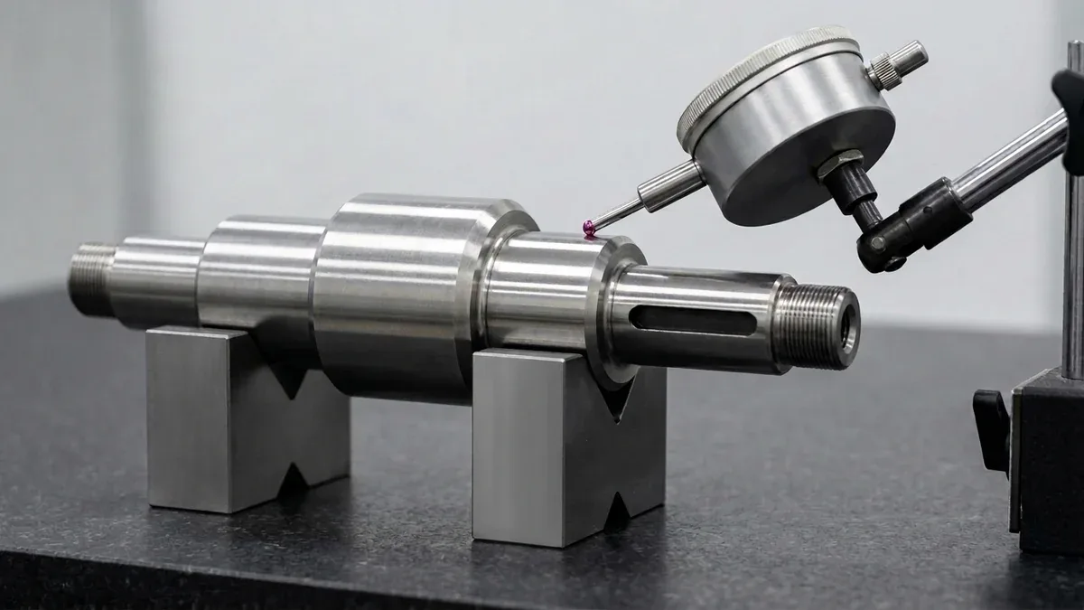
In CNC turning, the workpiece rotates along a continuous centerline while single-point carbide inserts slice material axially and radially. Because the primary cutting force is directed back against rigid machine guide ways and headstocks, turning achieves substantially tighter tolerances than milling:
- Diameter & Cylindricity Consistency: CNC lathes routinely hold outside diameters (OD) and internal bores (ID) within ± 0.008 mm (± 0.0003”) across high-volume production.
- Concentricity & Runout: When features are turned in a single chuck clamping, total indicator reading (TIR) runout and concentricity can be held within 0.005 mm.
- Swiss CNC Capabilities: For slender pins and shafts (L/D > 4), Swiss-type lathes support the workpiece directly against a carbide guide bushing adjacent to the cutting edge, virtually minimizing shaft deflection to within ±0.005 mm (±0.0002 in).
5. Tolerance Stack-Up: Why Perfect Individual Parts Fail Assembly
A frequent pitfall in mechanical engineering is tolerance stack-up (cumulative tolerance buildup). An assembly composed of ten individual CNC machined components, each compliant with its individual ± 0.10 mm drawing tolerance, can exhibit a total dimensional error accumulation of up to ± 1.0 mm under worst-case boundary conditions. As a result, dowel pins fail to enter alignment holes, O-rings fail to compress, or rotating shafts bind against bearing seats.
Engineers manage stack-up risk through two primary methodologies:
- Worst-Case Tolerance Analysis: Assumes all dimensions simultaneously hit their maximum or minimum tolerance boundaries (Stackmax = ∑ Ti). Essential for critical mission systems, aerospace flight controls, and medical implants where zero failure probability is mandatory.
- Root-Sum-Square (RSS) Statistical Tolerancing: Based on normal Gaussian distribution curves, RSS recognizes that independent manufacturing dimensions rarely drift to extreme limits at the same time:
Tassembly = √(∑ Ti²)
RSS analysis allows designers to safely specify more generous individual component tolerances without risking assembly interference, significantly reducing CNC machining unit costs. - Datum Baseline Dimensioning: Avoid chain-dimensioning (dimensioning each hole from the preceding hole). Instead, anchor all functional holes and mating surfaces to a single primary Datum edge or precision locating hole.
6. Critical Factors Dictating Achievable CNC Machining Tolerances
Achieving micron-level dimensional precision is not solely a matter of machine tool capability. At AS Prototypes, our engineering team manages five interrelated manufacturing variables:
1. Material Thermal Expansion (CTE)
Materials expand and contract in response to ambient shop temperature swings and friction-generated cutting heat.
Aluminum 6061-T6 has a Coefficient of Thermal Expansion (CTE) of approximately 23 × 10-6/K, compared to 16 × 10-6/K for 300-series stainless steel, and over 110 × 10-6/K for plastics like POM (Delrin) or PTFE. A 500 mm aluminum plate will expand by 0.115 mm during a temperature shift of 10°C—completely wiping out a ± 0.025 mm precision tolerance band unless parts are normalized in a climate-controlled inspection room.
2. Internal Residual Stresses
Cold-rolled and extruded metal stocks retain internal stresses from mill manufacturing. When large volumes of stock are milled away to create asymmetric pockets or thin-walled ribs, the balance of internal stresses is broken, causing parts to warp, twist, or cup days after machining. AS Prototypes overcomes this by utilizing stress-relieved plates (e.g., MIC-6 or 6061-T651/7075-T651) and executing intermediate unclamped stress relaxation or alloy-specific low-temperature stabilization cycles (150–165°C for 6061-T6; strictly ≤100–110°C or room-temperature unclamped relaxation for 7075-T651 to prevent over-aging) between roughing and final finishing passes.
3. Clamping & Workholding Distortion
Applying excessive clamping force in manual machine vises can elastic deform thin-walled rings or fragile housings. When released from the fixture after machining, the component relaxes back into an out-of-round or distorted state. Our machinists engineer custom soft jaws, vacuum chucks, and multi-point hydraulic fixturing to distribute clamping pressure evenly without inducing strain.
4. Surface Treatment & Coating Allowances
Surface finishing processes alter finished dimensions. Standard Type II sulfuric acid anodizing adds approximately 5 to 10 μm (0.005 – 0.010 mm) per surface, while Type III hardcoat anodizing adds 25 to 50 μm (0.025 – 0.050 mm). Electroless nickel plating, zinc plating, and powder coating similarly deposit measurable coating thickness. Engineers must clearly define on 2D drawings whether tolerances apply before coating or after coating, allowing machinists to pre-compensate feature dimensions during CNC cutting.
7. Advanced Metrology & Inspection Protocols at AS Prototypes
A tight tolerance is meaningless unless verified by calibrated metrology instruments in a controlled environment. Machining to ± 0.005 mm requires inspection equipment capable of measuring to at least one-tenth of that tolerance (0.0005 mm or 0.5 μm) according to the Metrology 10:1 Gauge Maker’s Rule (GUM).
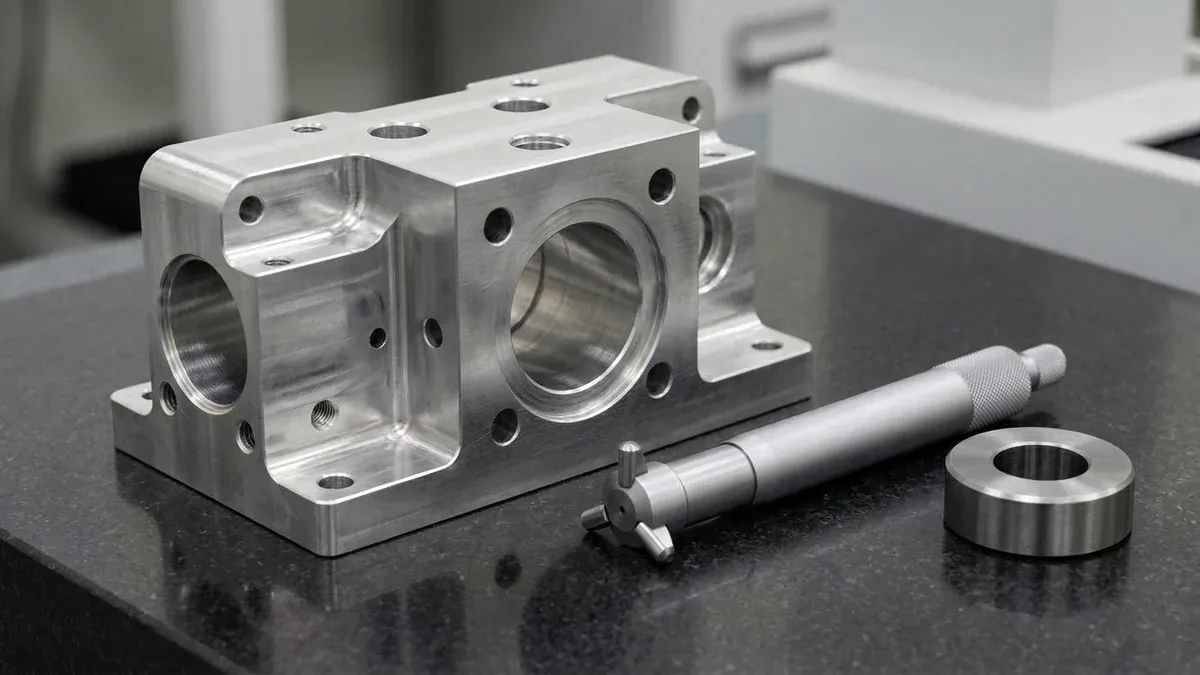
Our in-house metrology team operates a dedicated climate-controlled inspection laboratory maintained at a constant 20°C ± 1°C (68°F) and 45% relative humidity:
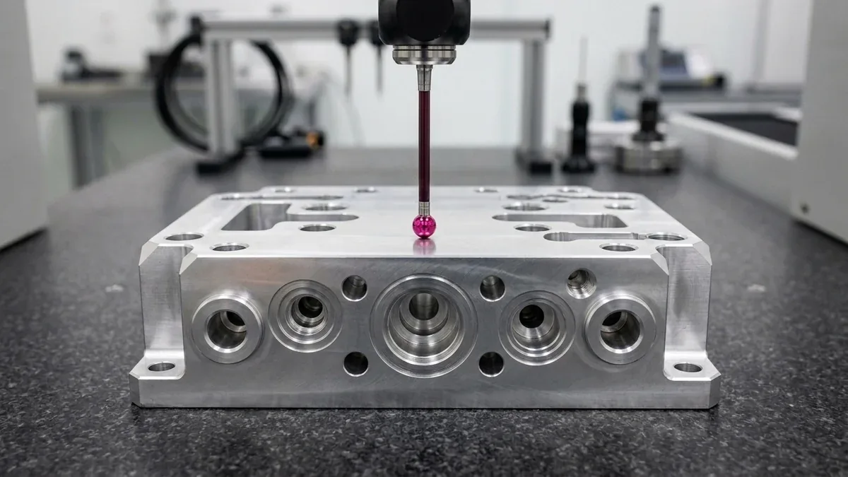
- Zeiss Bridge Coordinate Measuring Machine (CMM): Available upon request for critical dimensional verification, equipped with Renishaw motorized continuous-scanning ruby probes to verify multi-datum GD&T callouts, true position, surface profiles, and 3D compound contours directly mapped against CAD models.
- Mitutoyo Digital Micrometers & Three-Point Bore Gauges (Holtest): Calibrated digital outside micrometers and three-point internal bore micrometers featuring 0.001 mm scale resolution to verify ±0.005 mm to ±0.010 mm critical turned diameters and press-fit bearing bores.
- Calibrated Go/No-Go Pin & Thread Gauges: Precision tungsten carbide plug gauges and thread ring/plug gauges to verify hole and thread tolerances across production batches.
- 2.5D Optical Vision Measuring Systems (VMS): Non-contact optical coordinate measurement systems for inspecting delicate micro-features, thin plastics, and edge radii without mechanical probe contact distortion.
- Contact Stylus Surface Profilometers (ISO 4287): Verifying surface roughness parameters (Ra, Rz, Rq) to ensure milled and turned surfaces meet sealing requirements (Ra ≤ 0.4 μm to Ra ≤ 0.8 μm).
8. DFM Rules: How to Optimize Tolerances and Slash CNC Machining Costs
Tolerancing directly drives manufacturing economics. Adopting strategic Design for Manufacturability principles preserves functional integrity while dramatically reducing prototype and production expenses:
- Apply the “Selective Precision” Rule: Do not apply a global ±0.025 mm title block tolerance across an entire part. Restrict tight tolerances strictly to critical mating faces, bearing journals, and dowel locating holes. Permit non-critical external contours and clearance holes to relax to standard ISO 2768-m (± 0.1 mm to ± 0.2 mm).
- Avoid Over-Tolerancing Internal Radii: Sharp internal square corners cannot be cut by round rotating endmills without expensive wire EDM or microscopic tool passes. Specify internal corner radii at least 15% larger than the cutter radius (R ≥ 1.15 × rtool) to prevent tool chatter and corner deflection.
- Standardize Hole Sizes: Design hole diameters to match commercial drill bits and reamers (e.g., 6.00 mm, 8.00 mm). Non-standard hole diameters (e.g., 6.13 mm) require custom boring tools or helical circular interpolation, increasing machining cycle time.
- Provide Both 3D STEP and 2D PDF Drawings: While 3D models provide exact geometry for CAM toolpath programming, 2D PDF drawings are essential for declaring critical tolerances, datum reference frames, thread classes, and inspection notes.
Shop-Floor Cost-Tolerance Trade-Offs & When NOT to Over-Specify
When releasing production drawings for CNC machining tolerances guide, applying blanket ±0.010 to ±0.020 mm (±0.0004″ to ±0.0008″) tolerances across non-mating clearance features increases machining cycle time by 2.0× to 3.5× without improving functional assembly. Our DFM engineers recommend specifying ISO 2768-mK on general structural walls while isolating tight GD&T callouts strictly to functional bearing bores, dowel pins, and sealing interfaces.
In our Shenzhen facility, prismatic 3-axis and 4-axis vertical machining centers (VMCs) with contoured soft jaws handle 80%+ of structural setups with maximum rigidity and cost efficiency, reserving simultaneous 5-axis contouring strictly for compound-angle ports and organic impellers. Critical features undergo climate-controlled 20°C ± 1°C (68°F) metrology verification using calibrated Go/No-Go gauges, Mitutoyo three-point bore micrometers, and Zeiss Bridge CMM inspection (available upon request) prior to ex-factory release (4 to 8 business days for raw prototypes; 7 to 12 business days with MIL-A-8625 anodizing or ASTM A967 passivation).
🔗 Related CNC DFM & Metrology Engineering Guides:
To further optimize cycle time and dimensional stability in tight-tolerance CNC machined components, combine proper internal corner relief with datum-based coordinate inspection. Consult our shop-floor engineering guides on Maintaining Dimensional Stability in Thin-Wall Machining, Eliminating Sharp Internal Corners & Tool Deflection, and Precision CMM Metrology & GD&T Verification.
9. Technical Engineering FAQ
If no tolerance callouts are provided in the drawing title block or notes, AS Prototypes machines parts to ISO 2768-m (Medium) for metals, representing approximately ± 0.10 mm to ± 0.20 mm (± 0.004'' to ± 0.008'') for linear dimensions, and ± 0.20 mm to ± 0.40 mm for plastics.
On precision CNC milling and turning centers, we routinely hold ± 0.010 mm (± 0.0004''). For specialized components utilizing precision cylindrical grinding, Swiss-type CNC turning, or slow-feeding wire EDM, we achieve tolerances down to ± 0.005 mm (± 0.0002'') under controlled 20°C ± 1°C laboratory temperatures.
Plastics (such as Delrin, PEEK, PTFE, Nylon, and UHMW) exhibit coefficients of thermal expansion 4 to 8 times higher than aluminum or steel. Furthermore, low modulus of elasticity causes plastics to flex away from cutting tools, and moisture absorption can expand dimensions post-machining. Typical precision tolerances for engineering plastics are ± 0.05 mm to ± 0.127 mm.
CMM inspection is recommended whenever parts feature tight true position callouts (≤ 0.05 mm), multi-datum GD&T frames, complex 3D aerodynamic profiles, or critical aerospace/medical compliance mandates. Full First Article Inspection (FAI) reports with CMM data ensure 100% drawing compliance before shipment.
ISO 2768-m represents 'medium' general tolerance (±0.1 mm for 30–120 mm dimensions), ideal for commercial brackets and visual prototypes. ISO 2768-f designates 'fine' tolerance (±0.05 mm for 6–30 mm), used for precision mechanical fits.
Partner with Our Precision CNC Machining & Engineering Team
Eliminate tool deflection, residual stress distortion, and tolerance stack-up risks before production begins. Upload your 3D CAD files (STEP/IGES) and 2D GD&T drawings for a comprehensive shop-floor DFM review and custom quotation.
Upload 3D CAD for Engineering DFM & RFQ