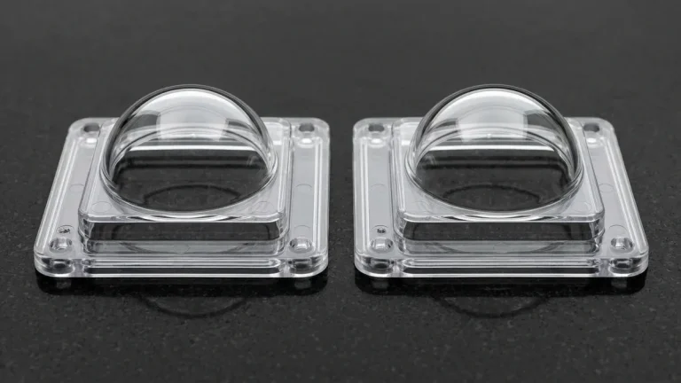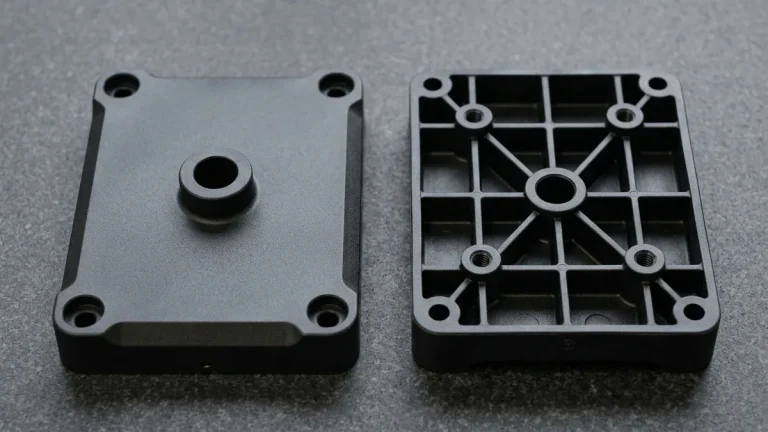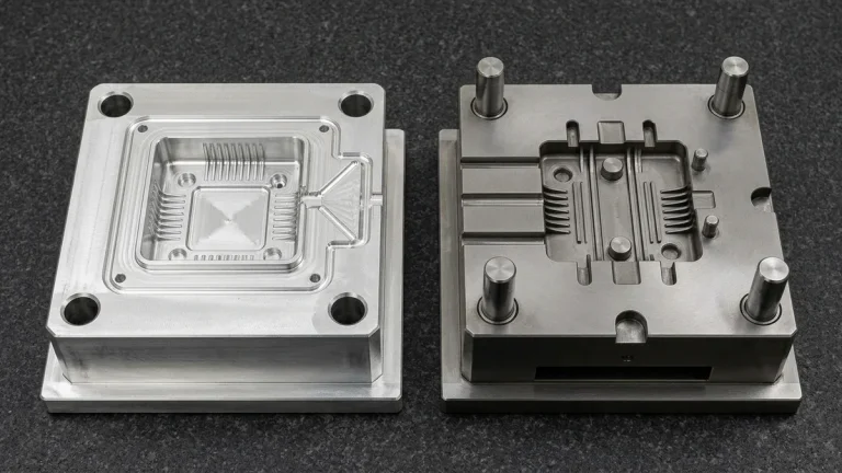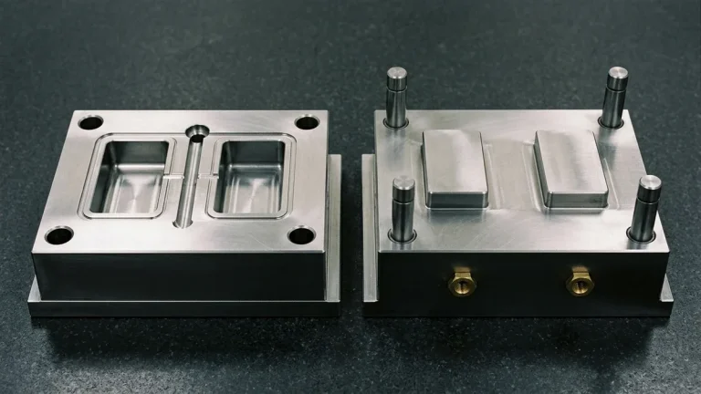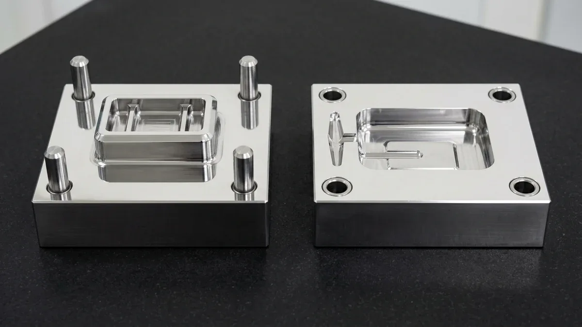
Plastic injection molding is the foundation of high-precision volume manufacturing, enabling hardware engineers to reproduce intricate, structurally robust polymer parts with sub-millimeter geometric accuracy across millions of cycles. However, transitioning a CAD model from 3D space into a production steel or aluminum tool requires navigating severe thermal, rheological, and mechanical constraints.
Molten thermoplastic resins behave as non-Newtonian, shear-thinning fluids that compress under intense hydraulic pressure, undergo significant volumetric contraction upon phase change, and freeze along dynamic cooling fronts. Without rigorous Design for Manufacturability (DFM) applied early in the engineering cycle, molds frequently suffer from short shots, sink marks, differential warpage, cosmetic weld lines, and premature tool steel erosion.
At AS Prototypes, our in-house tooling facility and injection molding engineers work directly with product development teams across the aerospace, automotive, medical device, and consumer electronics sectors. Producing high-yield tooling requires an integrated approach that couples advanced multi-axis CNC machining and wire EDM with scientific molding rheology. Below is an engineering analysis of injection mold design guidelines, mathematical modeling equations, tooling alloy selection matrices, and shop-floor defect prevention strategies.
- 1. Polymer Melt Rheology, PVT Shrinkage & Clamping Force Calculations
- 2. The Seven Definitive DFM Rules for Precision Injection Mold Design
- 3. Tooling Material Selection: Aluminum 7075 vs P20 vs NAK80 vs S136 ESR vs H13
- 4. Engineering Thermoplastics Matrix: Shrinkage Rates, Draft & Mold Temperatures
- 5. Shop-Floor Defect Troubleshooting Matrix: Tooling Root Causes & Corrective Actions
- 6. Precision Metrology, CMM Inspection & Parting Line Verification
- 7. Technical Engineering FAQ
1. Polymer Melt Rheology, PVT Shrinkage & Clamping Force Calculations
Before cutting cavity pockets or specifying mold bases, tooling engineers must calculate the hydrodynamic forces generated during the injection phase. Thermoplastic resins do not flow with constant viscosity; their apparent viscosity (η) drops precipitously as the shear rate (γ̇) increases according to the Cross-WLF or Ostwald-de Waele power-law model:
Where η0 is the zero-shear viscosity, τ* represents the critical shear stress level at the transition to shear thinning, and n is the power-law index (typically 0.20 to 0.45 for engineering plastics like ABS, PC, and PA66). As the screw drives polymer melt through runners, gates, and cavity thin walls, shear heating lowers localized viscosity, facilitating cavity filling before the melt freezes against the water-cooled mold steel.
Simultaneously, the tool must withstand enormous cavity pressures without parting line breathing, which produces chronic flash. Required press clamping force is calculated using both SI mechanical units and practical shop-floor metric tonnage conversions:
Tclamp (Metric Tons) ≈ [ Pcavity (bar) · Aprojected (cm²) · Sf ] / 1000
Where Tclamp represents required machine clamp tonnage (with 1 metric ton ≈ 9.807 kN), Pcavity is the average cavity pressure (ranging from 300 to 500 bar / 30–50 MPa for commodity polyolefins up to 800 to 1,200 bar / 80–120 MPa for high-viscosity polycarbonate or glass-filled PEEK), Aprojected is the total projected area of all moldings, runners, and sprues perpendicular to the platen clamping axis, and Sf is an engineering safety margin (typically 1.15 to 1.25). Correct calculation prevents parting line deflection while avoiding excessive tonnage that crushes precision mold vents.
2. The Seven Definitive DFM Rules for Precision Injection Mold Design
Successful injection molding relies on establishing balance across three competing domains: part structural performance, thermal mold cooling kinetics, and tool steel cutting mechanics. Deviations from established DFM principles lead to part defects and costly tooling re-cuts. The following seven rules represent mandatory engineering criteria for any component destined for injection tooling.
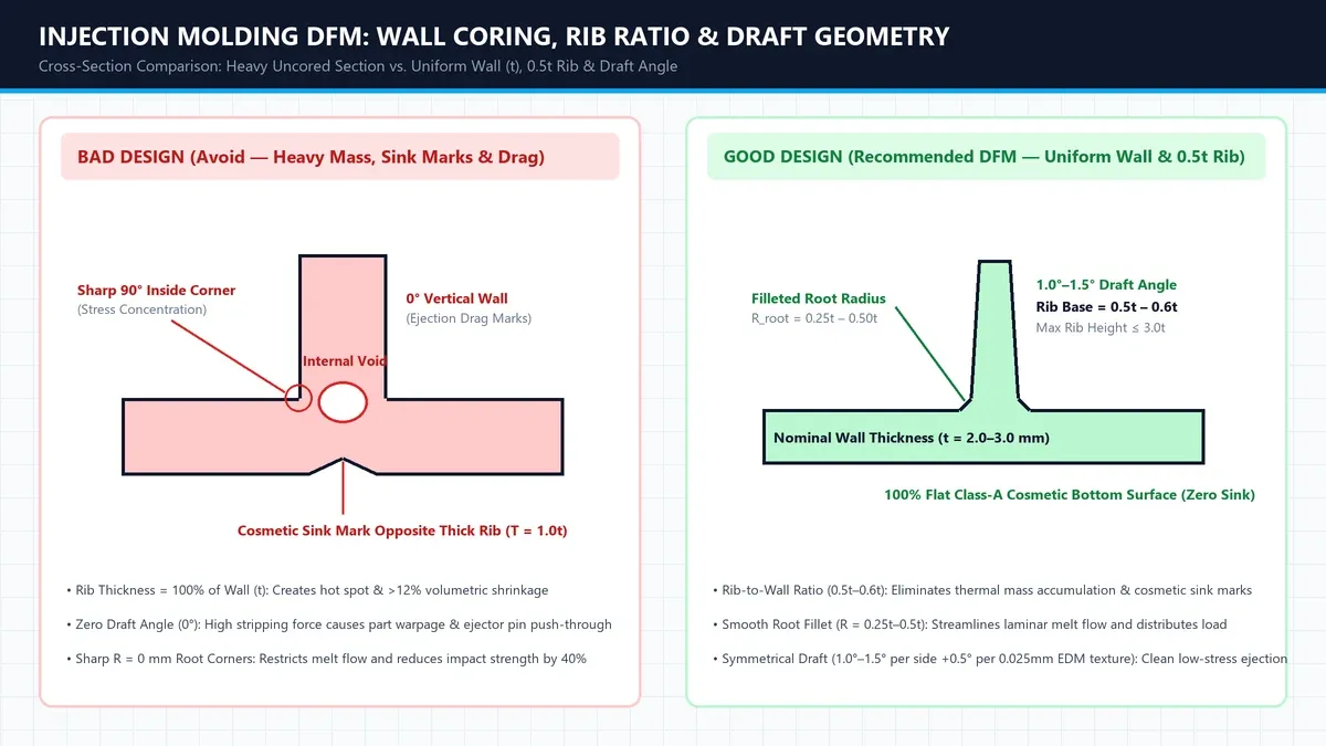
Rule 1: Uniform Nominal Wall Thickness & 1D Cooling Time Kinetics
The primary geometric parameter dictating part quality, cycle time, and dimensional stability is nominal wall thickness uniformity. When a molding features adjacent sections of disparate thicknesses, polymer melt flows preferentially through thick cross-sections (the racetrack effect), leading to air entrapment, hesitation marks, and unbalanced packing. More critically, cooling time (tc) scales quadratically with wall thickness (h), as derived from one-dimensional transient thermal conduction theory:
Where α is the thermal diffusivity of the polymer (α = k / (ρ · Cp)). Doubling a wall thickness from 1.5 mm to 3.0 mm quadruples the required in-mold cooling time, drastically inflating cycle times and piece-part costs. When thin outer skins solidify while an internal thick core remains molten, volumetric thermal shrinkage pulls the frozen skin inward, resulting in cosmetic sink marks or internal vacuum voids.
To maintain structural integrity without creating thick sections, design engineers must core out solid bosses and intersections, replacing heavy solid sections with hollowed-out cavities supported by thin ribs. When wall transitions are functionally unavoidable, implement a gradual transition ramp with a minimum 3:1 length-to-thickness ratio (≤18° slope) to ensure uniform melt front advancement and continuous packing pressure transmission.
Rule 2: Draft Angles & Mold Separation Ejection Shear Mechanics
As molten resin cools and solidifies within the tool cavity, it contracts away from outer cavity steel while clamping tightly onto core male features due to diametral volumetric shrinkage. Without draft angles (taper) on all vertical surfaces parallel to the mold opening direction, mechanical ejection forces must overcome severe normal friction across the entire ejection stroke:
Where E is the polymer flexural modulus at ejection temperature, αs is the linear coefficient of thermal expansion (CLTE), ΔT is the thermal delta between mold temperature and ejection temperature, Acontact is the vertical contact surface area, μ is the dynamic coefficient of friction (typically 0.20 to 0.40 for steel-on-polymer), and θ is the draft angle.
The critical advantage of draft is kinematic: as soon as the ejector system displaces the part by an infinitesimal axial distance (δx), a physical clearance gap (δx · tan θ) immediately opens between core steel and part walls, reducing normal contact force to zero.
Conversely, with zero draft (θ = 0°), high frictional drag persists throughout the entire ejection stroke, inducing pin punch-through marks, deep cosmetic drag scoring, part distortion, or tool cavity retention.
Our toolmaking standards require the following minimum draft angles:
- High-Polish Optical & Gloss Finishes (SPI-A1, SPI-A2, SPI-B1): Minimum 1.0° to 1.5° per side. Zero-draft conditions should be avoided unless shut-off lifters or side-action mechanisms are integrated.
- Satin & Fine Spark Finishes (SPI-C1, SPI-C2, VDI 18–24): Minimum 2.0° to 2.5° per side to release microscopic EDM surface asperities without micro-tearing.
- Textured Surfaces (Mold-Tech MT-11010 to MT-11050): Enforce 1.0° of draft for every 0.025 mm (0.001 in) of texture etch depth, plus a baseline 1.5°. A 0.05 mm textured leather grain requires at least 3.5° to 4.0° draft per side to prevent severe drag scuffing during ejection.
- Core vs. Cavity Bias: Apply greater draft to the cavity half (e.g., 2.0°) than the core half (e.g., 1.0°) to ensure the molded part remains securely on the moving ejector half upon mold opening.
Rule 3: Rib-to-Wall Ratios (40%–60%) & Local Mass Balance
Structural ribs provide torsional stiffness, prevent flexural bending, and guide resin flow into thin sections without adding substantial part weight. However, where a rib attaches to an exterior class-A cosmetic wall, the combined intersection forms a localized geometric mass accumulation. Using inscribed circle geometry, the exact diameter of the maximum inscribed circle at a 90° T-junction without fillets is:
If a rib base thickness equals the nominal wall (trib = 1.0 twall), the inscribed circle diameter expands to 1.25 twall, which represents a 56% increase in localized volumetric thermal mass (ΔV ∝ D²). This thick thermal core stays molten long after the exterior skin has frozen; as it solidifies, volumetric contraction exerts inward tensile pull on the frozen skin, generating unsightly sink marks visible under oblique ambient lighting.
To completely prevent sink marks while maintaining structural rigidity, implement these rib geometry rules:
- Base Rib Thickness: Target 40% to 50% of nominal wall thickness for high-shrinkage crystalline resins (POM, PA66, PP) and 50% to 60% for low-shrinkage amorphous resins (ABS, PC, PBT).
- Maximum Rib Height: Limit total rib height to 2.5 to 3.0 times nominal wall thickness to avoid deep, narrow tool steel pockets that trap air and impede EDM graphite electrode flushing.
- Base Fillet Radius: Blend rib roots with a radius of 0.25 to 0.40 times nominal wall thickness (R = 0.25–0.40 twall). A smaller radius concentrates stresses, while a larger radius increases localized thermal mass, inducing sink marks.
- Spacing Between Ribs: Maintain at least 2.0 to 2.5 times nominal wall thickness between parallel ribs to ensure sufficient steel width between cutter passes and facilitate water line cooling passage.
Rule 4: Internal Radii & Notch Stress Concentration Factor (Kt)
Sharp internal corners represent the most frequent point of failure in molded plastic components. Under dynamic mechanical loading, sharp 90° inside transitions act as stress risers, concentrating localized operational stresses beyond the ultimate tensile strength of the polymer. The empirical stress concentration factor (Kt) under corner bending (per Covestro / Bayer structural plastics design guidelines) is modeled as:
When the internal radius ratio (Rint / t) is less than 0.15 (a quasi-sharp corner), Kt spikes above 3.0, making the component brittle and susceptible to notch fracture under impact. Conversely, when Rint / t is maintained between 0.50 and 0.60, Kt drops to a benign ~1.6 to 1.7, distributing bending stresses smoothly across the corner transition.
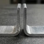
From a tooling perspective, sharp internal corners cannot be machined directly using rotating CNC endmills without resorting to secondary sinker EDM spark erosion. Radiused corners reduce machining cycle times, extend tool life, and promote laminar, low-shear resin flow during mold filling. To prevent localized wall thickening through corner bends, always set the outside radius to the inside radius plus wall thickness:
Rule 5: Parting Line Placement & Shut-Off Angle Architecture
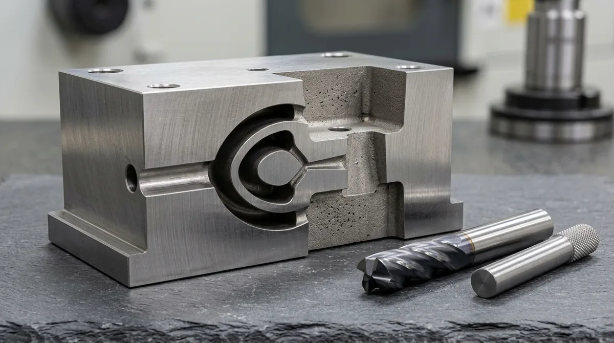
The parting line (PL) establishes the primary interface where the stationary cavity half (A plate) and mobile core half (B plate) clamp together under tonnage. Strategic parting line placement dictates mold manufacturing complexity, cosmetic seam visibility, and side-action mechanical actuation requirements. Molds should feature flat, planar parting lines whenever possible to minimize CNC five-axis surfacing time and facilitate precision tool bench spotting.
When windows, snap-fit latches, or through-holes require the A-plate and B-plate steel to interlock (kiss-off shut-offs), direct vertical zero-degree contact is impermissible. Metal-on-metal sliding contact at 0° induces galling, adhesive friction wear, and rapid steel erosion, causing severe parting line flash within a few thousand cycles. Mold engineering rules mandate:
- Bypass Shut-Off Angle: Incorporate a minimum 3.0° to 5.0° draft angle on all kissing shut-off faces. For high-speed production tools running abrasive resins, specify 7.0°.
- Aesthetic Feature Alignment: Align the parting line along crisp perimeter feature lines, radii tangents, or bottom edges to conceal the residual witness line.
- Tool Venting Architecture: Machine precision gas vents along the parting line perimeter opposite the gate, sized to resin-specific flash thresholds: 0.015 mm to 0.025 mm depth for crystalline resins (PA66, POM, PP) and 0.030 mm to 0.050 mm for high-viscosity amorphous resins (PC, ABS, PMMA). Adequate venting prevents localized dieseling burn marks caused by adiabatic compression of trapped mold cavity air.
Rule 6: Runner Dynamics, Gate Sizing & Maximum Shear Rate Limits
The gating system is the hydraulic conduit connecting the machine nozzle, sprue, and cold/hot runners directly into the molded part cavity. Incorrect gate dimensions or improper gate location trigger jetting, residual packing stress, gate blush, and weak weld lines. The maximum apparent wall shear rate (γ̇w) through circular gates (sub-gates, pin gates) and rectangular gates (edge gates, fan gates) during peak injection velocity is modeled as:
Where Q is volumetric flow rate (cm³/s), dgate is hydraulic gate diameter, wgate is gate width, and hgate is gate land depth. Tooling engineers must ensure the shear rate remains below the polymer’s critical degradation limit (typically 20,000 to 50,000 s−1 for polycarbonate, polyamides, and acetal) to prevent polymer chain scission, silver streaking, splay, and localized mechanical embrittlement.
Primary gating design imperatives include:
- Gate into Thick Sections: Always position the gate at the thickest nominal cross-section. Gating into thick walls allows the packing phase to compensate for volumetric thermal shrinkage in the core before thin downstream sections freeze.
- Impingement Gating: Direct incoming melt streams against a nearby cavity wall, core pin, or rib feature. Unrestricted gating into deep open cavities causes turbulent melt jetting (snake-like stream flow), producing severe cosmetic blemishes and localized flow marks.
- Sub-Marine (Tunnel) & Cashew Gates: Use submarine gates (tunneling beneath the parting line at 30°–45° with a 0.8–1.5 mm diameter) for automated part separation and degating during mold opening, eliminating secondary manual trimming operations.
- Weld Line Positioning: Orient gate locations such that advancing flow fronts merge in non-structural, low-visibility zones. Weld lines (knit lines) exhibit a 20% to 50% reduction in tensile and impact strength compared to bulk resin properties.
Rule 7: Conformal Cooling Layout & Reynolds Turbulent Heat Transfer
Cooling accounts for 70% to 80% of the total injection molding cycle time. Uneven heat extraction between the core half and cavity half induces differential through-thickness thermal stress, causing part warpage after mold ejection. To ensure rapid, uniform heat dissipation, the cooling fluid circulating through drilled mold channels must achieve fully turbulent flow, characterized by a Reynolds number (Re) exceeding 4,000:
Under turbulent flow conditions, the convective heat transfer coefficient (hconv) increases by 300% to 500% compared to stagnant laminar flow, as governed by the Dittus-Boelter correlation (Nu = 0.023 · Re0.8 · Pr0.4). On the shop floor, maintaining a minimum volumetric flow rate of 2.5 to 4.0 liters per minute per cooling circuit through standard 10 mm drilled lines guarantees turbulent conditions. Traditional gun-drilled cooling circuits must adhere to balanced geometry:
- Channel Diameter (D): Standardize on 8 mm to 12 mm drilled circuits.
- Channel Depth from Part Surface: Position water lines at a depth of 1.5 to 2.5 times channel diameter (12 mm to 25 mm). Placing lines too close causes hot/cold surface banding; placing them too deep slows heat transfer.
- Channel-to-Channel Pitch: Space water lines 2.5 to 3.5 times channel diameter apart to create an overlapping, uniform thermal extraction gradient.
- Additive Conformal Cooling Inserts: For complex, deep-draw cores where straight gun drills cannot reach, integrate 3D printed tool steel inserts (DMLS 1.2709 maraging steel). Conformal cooling channels curve along part geometry at a constant distance, reducing cooling cycle times by 20% to 35% while eliminating post-mold warpage.
3. Tooling Material Selection: Aluminum 7075 vs P20 vs NAK80 vs S136 ESR vs H13
Selecting the appropriate mold tooling substrate represents a strategic engineering decision balancing upfront tooling investment, thermal cycle efficiency, component cosmetic specifications, and total production volume. At AS Prototypes, our precision toolroom builds molds across five alloy tiers:
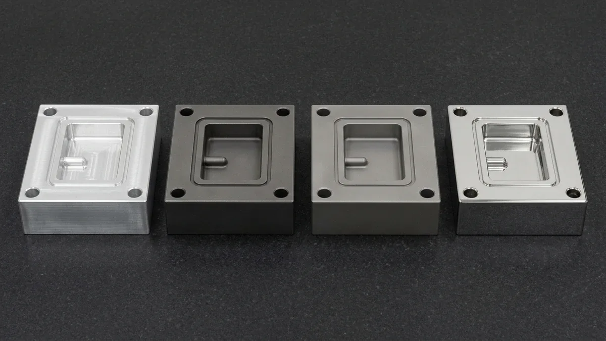
- Aircraft Aluminum 7075-T651 (Rapid Prototype & Bridge Tooling): Aluminum 7075-T651 is the premier alloy for bridge production runs spanning 5,000 to 25,000 shots. With an exceptional thermal conductivity of ~130 W/m·K—nearly five times higher than standard tool steels—7075 aluminum extracts heat rapidly, shortening cycle times by 25% to 40%. It machines with high surface feeds on CNC milling centers, condensing rapid tooling turnaround to 18 to 25 business days. It accepts SPI B-1 to B-3 finishes, though abrasive glass-filled resins accelerate gate wear.
- Pre-Hardened AISI P20 (Pilot & Mid-Volume Tooling): The industry benchmark for pre-series pilot builds and production volumes spanning 50,000 to 250,000 shots. Supplied pre-hardened to 28–34 HRC, P20 requires no secondary through-hardening heat treatment, preventing post-machining distortion. It offers uniform structural machinability and reliable sinker EDM spark characteristics.
- Daido NAK80 Precipitation-Hardened Steel: Supplied at 38–42 HRC, NAK80 provides an ultra-dense, inclusion-free grain structure capable of sustaining SPI A-2 to SPI A-1 high-gloss diamond finishes without pinholes. Ideal for high-cosmetic consumer electronics bezels, medical enclosures, and optical light guides.
- Stavax S136 ESR Through-Hardened Stainless Steel: Vacuum furnace quenched and double-tempered to 48–54 HRC, Electro-Slag Remelted (ESR) S136 stainless steel provides total resistance against corrosive outgassing from flame-retardant resins (PVC, POM, halogenated blends). Its ultra-pure microstructure achieves mirror-grade optical finishes (<0.025 μm Ra) for critical cosmetic and medical assemblies exceeding 500,000 to 1,000,000+ shots.
- AISI H13 Chromium Hot-Work Tool Steel: Quenched and tempered to 46–52 HRC, H13 delivers superior thermal fatigue resistance and impact toughness. It is the premier substrate for molding high-temperature engineering polymers loaded with 30% to 50% glass or carbon fibers (e.g., PEEK-GF30, PA66-GF33), preventing gate wash and abrasive sliding wear.
| Tooling Alloy Grade | Hardness Level | Thermal Conductivity | Polishability Standard | Rated Tooling Life (Shots) | Tooling Turnaround Lead Time |
|---|---|---|---|---|---|
| Aluminum 7075-T651 | 150 HBW (~87 HRB) | 130 W/m·K | SPI B-1 to B-3 (Paper) | 5,000 – 25,000 | 18 – 25 Business Days |
| AISI P20 | 28 – 34 HRC | 29 – 34 W/m·K | SPI B-1 to SPI A-3 | 50,000 – 250,000 | 20 – 28 Business Days |
| Daido NAK80 | 38 – 42 HRC | 41 W/m·K | SPI A-2 to SPI A-1 (Diamond) | 100,000 – 350,000 | 22 – 30 Business Days |
| Stavax S136 ESR | 48 – 54 HRC (Hardened) | 20 W/m·K | SPI A-1 (<0.025 μm Ra Mirror) | 500,000 – 1,000,000+ | 25 – 35 Business Days |
| AISI H13 | 46 – 52 HRC (Hardened) | 24 W/m·K | SPI A-3 to SPI B-1 | 500,000 – 1,000,000+ | 25 – 35 Business Days |
4. Engineering Thermoplastics Matrix: Shrinkage Rates, Draft & Mold Temperatures
Tool cavity sizing is not identical to nominal part CAD dimensions. Cavity steel dimensions must be scaled outward according to the resin’s isotropic or anisotropic volumetric shrinkage rate (ΔL = L0 · S). Semicrystalline polymers exhibit higher volumetric shrinkage than amorphous polymers due to polymer chain folding and crystal lattice densification during cooling. The table below details critical processing parameters for standard engineering polymers:
| Resin Polymer Grade | Polymer Morphology | Volumetric Shrinkage (%) | Nominal Wall Range | Min Draft Angle | Mold Tool Temperature |
|---|---|---|---|---|---|
| ABS (Terpolymer) | Amorphous | 0.4% – 0.7% | 1.2 mm – 3.0 mm | 1.0° | 50°C – 70°C |
| PC (Polycarbonate) | Amorphous | 0.5% – 0.8% | 1.5 mm – 3.5 mm | 1.5° | 80°C – 110°C |
| PC + ABS Blend | Amorphous Blend | 0.5% – 0.7% | 1.4 mm – 3.2 mm | 1.0° – 1.5° | 60°C – 85°C |
| POM (Acetal / Delrin) | Semicrystalline | 1.8% – 2.5% | 1.0 mm – 3.0 mm | 1.5° | 80°C – 105°C |
| PA66 + 30% GF | Semicrystalline / Fiber | 0.3% Flow / 0.8% Cross | 1.2 mm – 3.0 mm | 1.5° – 2.0° | 80°C – 110°C |
| PP (Polypropylene) | Semicrystalline | 1.2% – 2.2% | 0.8 mm – 3.0 mm | 1.0° – 1.5° | 30°C – 60°C |
| PEEK (Unfilled) | Semicrystalline High-Temp | 1.2% – 1.5% | 1.5 mm – 3.5 mm | 2.0° | 160°C – 190°C (Oil/Elec) |
5. Shop-Floor Defect Troubleshooting Matrix: Tooling Root Causes & Corrective Actions
When molding non-conformances emerge during T1 sampling, distinguishing between processing parameter adjustments and required tooling steel modifications is critical. The engineering matrix below maps primary molding defects to their root causes and verified remedies:
| Molded Defect | Physical Root Cause | Tooling Modification Remedy | Process Parameter Remedy |
|---|---|---|---|
| Sink Marks / Voids | Localized volumetric shrinkage in thick rib roots or bosses; premature gate freeze-off. | Thin rib base to 40%–50% of wall; core out solid bosses; enlarge gate land and diameter. | Increase packing pressure; extend hold time; lower melt temperature. |
| Part Warpage | Differential cooling rates between core and cavity halves; anisotropic fiber orientation. | Balance cooling circuit pitch and depth; add bubblers or baffles to hot core pins; re-orient gates. | Adjust core vs cavity water temperature delta; extend in-mold cooling time. |
| Weld / Knit Lines | Two cold polymer flow fronts converge around a core pin with insufficient thermal fusion. | Relocate gate to move weld line to low-stress zone; add perimeter gas vents at convergence point. | Increase melt temperature and injection speed; elevate mold wall temperature. |
| Dieseling / Burns | Trapped cavity air undergoes adiabatic compression, heating beyond resin auto-ignition temp. | Add parting line vents (0.02 mm depth); incorporate porous sintered metal venting pins. | Reduce injection velocity near end of stroke; reduce clamping tonnage slightly if over-clamped. |
| Flash (Parting Line) | Melt pressure exceeds clamp force; parting line damage or insufficient shut-off angle. | Spot and blue parting line plates; re-machine shut-offs with ≥5° draft; verify insert flatness <0.01 mm. | Transfer press to higher clamp tonnage; reduce injection pressure and peak pack pressure. |
| Short Shots | Flow hesitation in thin ribs; excessive flow length to thickness ratio (L/t); premature freeze. | Thicken restrictive walls; increase gate land diameter; add flow leaders or additional gates. | Increase shot size and switchover position; raise injection speed and barrel temperatures. |
6. Precision Metrology, CMM Inspection & Parting Line Verification
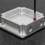
Quality assurance for high-precision injection tooling relies on coordinate metrology. Prior to assembling mold bases and running initial trial shots (T1), critical cavity and core inserts undergo precision Zeiss CMM verification in a temperature-controlled metrology laboratory (maintained at 20°C ± 1°C). High-precision coordinate measuring machines equipped with touch-trigger ruby probe styli verify critical tooling geometry against the master 3D CAD model:
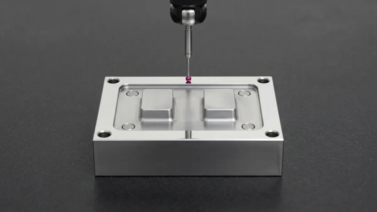
Dimensional metrology protocols focus on three critical tooling boundaries:
- Datum A Parting Line Planar Flatness: Verifying that the primary parting line shut-off land maintains coplanarity within ±0.005 mm to ±0.008 mm across the entire block face. Any localized depression causes resin flashing, while a high spot concentrates clamping forces, resulting in tool steel coining and brinelling.
- Core-to-Cavity Alignment & Interlocking Tapers: Measuring four-corner precision interlocks and leader pin bushings to guarantee side-to-side registration within ±0.005 mm. Misalignment causes uneven nominal wall thickness across symmetrical split enclosures.
- First Article Inspection (FAI) of T1 Moldings: Following initial T1 sampling, molded parts undergo 2.5D optical vision inspection and multi-point CMM tactile probing (available upon request for critical dimensional verification) to evaluate volumetric shrinkage, GD&T profile of a surface tolerances (≤±0.10 mm standard ISO 2768-mK, down to ±0.02 mm for precision gears), and true position of critical core pin holes.
7. Technical Engineering FAQ
When a rib intersects a nominal exterior wall, the intersection creates a localized accumulation of plastic mass. According to inscribed circle geometry, the junction's thermal volume expands significantly beyond the surrounding wall thickness. During cooling, the exterior surface freezes first while the internal core remains molten. As this trapped molten core cools and contracts, it exerts inward capillary tension, pulling the outer skin inward and creating a cosmetic depression known as a sink mark. Restricting rib base thickness to 40%–60% balances mechanical stiffness while keeping the inscribed circle mass small enough to solidify without visible sinking.
Aircraft aluminum 7075-T651 tooling is ideal for prototype validation, market-entry testing, and bridge production runs spanning 5,000 to 25,000 shots. Aluminum delivers a thermal conductivity of ~130 W/m·K—nearly five times higher than standard tool steels—which dissipates heat rapidly and reduces in-mold cooling cycle times by 25% to 40%. Aluminum tools machine with significantly higher cutting speeds on CNC mills, compressing turnaround times to 18 to 25 business days at substantially lower tooling capital expenditure. However, for abrasive glass-reinforced resins or multi-cavity runs exceeding 100,000 shots, through-hardened S136 ESR or H13 tool steel remains necessary.
Warpage is caused by differential volumetric shrinkage across different regions of a molded part. This distortion arises from three primary factors: non-uniform nominal wall thicknesses, asymmetric cooling rates between the core half and cavity half, or anisotropic molecular/fiber orientation in glass-filled polymers. When one side of a part solidifies and contracts faster than the opposite side, residual bending stresses warp the component upon mold ejection. Engineering balanced cooling channels with turbulent water flow (Reynolds number >4,000) and integrating 3D printed conformal cooling circuits around deep cores extracts heat uniformly, eliminating residual thermal bending moments.
For through-holes, side windows, or snap-fit pockets formed by kissing shut-offs where A-plate and B-plate steel interlock, design engineers must specify a minimum draft angle of 3.0° to 5.0°. Vertical 0° shut-offs cause steel-on-steel sliding friction during clamping and mold opening, inducing severe adhesive galling and mechanical erosion that creates chronic parting line flash within a few hundred cycles. A 3°–5° shut-off ensures clean metal separation without sliding friction wear.
Glass-fiber reinforced resins (such as PA66-GF30 or PBT-GF20) present severe mechanical abrasiveness and anisotropic shrinkage. Tool steel must be upgraded from aluminum or P20 to through-hardened AISI H13 or Stavax S136 ESR heat-treated to 50–54 HRC to prevent rapid gate wash and runner erosion. Draft angles must be increased by at least 0.5° to 1.0° over baseline standards to overcome higher frictional resistance during ejection. Furthermore, gating must be strategically located along major load axes, because shrinkage parallel to fiber alignment (typically ~0.3%) is significantly lower than cross-flow shrinkage (~0.8%), which can induce severe differential warpage if gating creates turbulent flow fronts.
Transition Seamlessly from Rapid Tooling to High-Precision Molding
Optimize cavity life, gate geometry, and part unit economics with our in-house tooling and injection molding engineering team. Upload your 3D CAD models (STEP/IGES) for a comprehensive Moldflow and DFM manufacturability assessment.
Upload 3D CAD for Tooling & Molding DFM Review