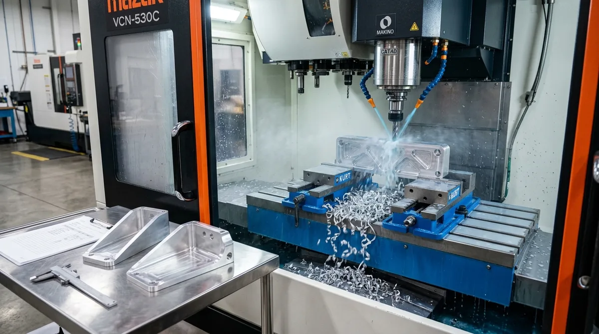
Aluminum alloys are celebrated across the aerospace, automotive, robotics, and consumer electronics industries for their exceptional strength-to-weight ratio, superior thermal conductivity, and high machinability ratings. However, many mechanical engineers inadvertently inflate component costs by 50% to 200% simply by designing features that are hostile to high-speed CNC milling cutters. To successfully reduce aluminum CNC machining costs, engineering teams must apply proactive Design for Manufacturability (DFM) principles early in the CAD modeling stage. By optimizing internal corner radii, eliminating excessively deep pockets, minimizing workholding setups, and selecting near-net-shape stock, you can dramatically compress cycle times and drive down piece-part pricing without compromising mechanical function.
1. Increase Internal Corner Radii (Avoid Sharp Corners)
Because CNC milling tools are cylindrical, cutting a 90° sharp vertical internal corner is physically impossible. When a CAD model contains sharp corners, machine shops are forced to either utilize slow wire EDM or deploy fragile micro-end mills (e.g. 1.0 mm diameter) operating at drastically reduced feed rates.
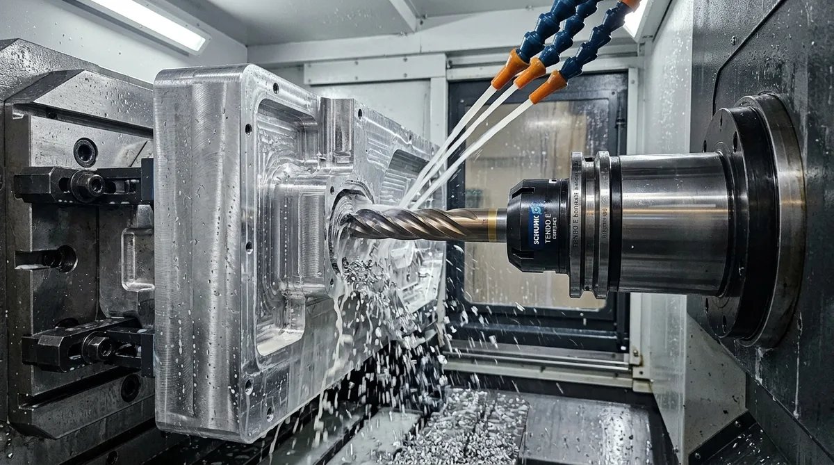
- The Golden Radius Rule: Ensure the internal corner radius is at least 1/3 of the cavity depth. For example, if a pocket is 12 mm deep, specify an internal corner radius of at least 4 mm.
- Add 0.5 mm Cutter Clearance: If you design a corner with an exact 3.0 mm radius, a standard 6.0 mm cutter must come to an abrupt full-engagement stop, causing chatter and premature tool wear. Designing a 3.5 mm or 4.0 mm radius allows the cutter to dynamically roll around the corner without decelerating, reducing cycle time by up to 25%.
2. Limit Pocket Depth-to-Width Ratios (Avoid Tool Deflection)
Deep, narrow cavities significantly increase machining difficulty. As end mill reach extends beyond 3 to 4 times its diameter, tool deflection and harmonic chatter escalate exponentially, forcing machinists to take shallow micro-depth cuts.
- Maintain a 4:1 Depth Ratio: For standard end mills, keep internal pocket depths within 4 times the tool diameter. For example, a pocket machined with a 10 mm end mill should ideally not exceed 40 mm in depth.
- Open Pocket Architecture: Wherever structurally feasible, convert enclosed blind pockets into open-sided U-channels or through-slots. This permits horizontal chip evacuation, prevents chip re-cutting, and allows large-diameter roughing cutters to run at maximum material removal rates (MRR).
3. Minimize Machine Setups (Consolidate Machining Orientations)
Every time an operator must stop the CNC machine, unclamp the part, rotate it into a secondary fixture, and re-probe work datums, labor costs accumulate while positional tolerance stack-up risks increase:
- Align Features along One or Two Primary Axes: Aim to design all pockets, tapped holes, and counterbores accessible from the top or top-and-bottom setups.
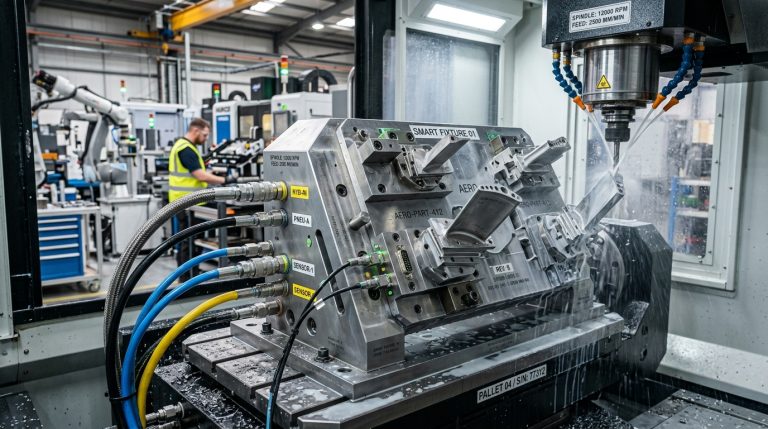
- Leverage 5-Axis Single-Clamping: When complex geometries require multi-face machining, utilizing our precision 5-axis CNC machining centers allows all 5 sides to be cut in a single clamping setup, eliminating custom soft-jaw tooling fixtures and cutting lead times by days.
4. Rationalize GD&T Tolerances (Avoid Over-Tolerancing)
Tolerances tighter than ±0.025 mm (±0.001 in) require specialized temperature-controlled environments, specialized finishing cutters, frequent spindle touch-probing, and coordinate measuring machine (CMM) inspections that dramatically increase unit costs.
- Apply General Tolerances (ISO 2768-mK): Specify standard general tolerances (±0.1 mm to ±0.2 mm) for non-mating exterior surfaces, cosmetic steps, and clearance pockets.
- Reserve Tight Tolerances for Critical Interfaces: Restrict tight tolerances (±0.005 mm to ±0.015 mm) strictly to bearing bores, dowel pin locating holes, and hydraulic O-ring gland depths.
Cost Impact: DFM Feature Comparison Matrix
The table below summarizes common CAD design bottlenecks and their cost-optimized manufacturing alternatives:
| Design Feature | High-Cost Engineering Choice | Cost-Optimized DFM Alternative | Cost Reduction Potential |
|---|---|---|---|
| Internal Cavity Corners | Sharp 90° vertical edges (requires EDM) | Radiused corners (R ≥ 1/3 depth + 0.5 mm) | 30% – 50% cycle time reduction |
| Pocket Depth | Deep cavities (>6x tool diameter) | Shallow stepped pockets (≤4x tool diameter) | 40% faster material removal rate |
| Machining Orientations | Features on 5 or 6 opposing faces | Features grouped on 1–2 faces, or 5-axis setups | Eliminates 3–4 manual re-clamping setups |
| Tolerances | Blanket ±0.01 mm callout across entire drawing | ISO 2768-mK general, tight only on critical fits | 25% – 35% reduction in inspection & cycle time |
| Threaded Holes | Deep blind threads (>3x hole diameter) | Through-holes or depth ≤ 2x hole diameter | Eliminates tap breakage & hand-tapping |
5. Standardize Thread Depths & Tap Sizes
Excessively deep tapped threads add no structural holding strength while dramatically increasing tap breakage risk:
- Limit Thread Depth to 2x–3x Diameter: In aluminum, 1.5 to 2 times the nominal bolt diameter provides maximum tensile pullout strength (e.g. 6 to 9 mm engagement for an M3 bolt). Threading beyond 3x adds unnecessary tool wear and pecking cycles.
- Standardize Thread Pitches: Utilize standard coarse metric (M3x0.5, M4x0.7, M6x1.0) or UNC threads that utilize standard in-stock CNC spiral-flute taps rather than specialized fine pitches.
6. Select the Right Aluminum Alloy for the Application
Different aluminum alloys possess drastically different raw material costs and cutting speeds:
| Aluminum Alloy | Machinability Rating | Raw Material Cost Tier | Best Economic Use Case |
|---|---|---|---|
| Al 6061-T6 | Excellent (100% Benchmark) | Moderate / In-Stock Standard | Universal workhorse for structural brackets, enclosures, and housings |
| Al 7075-T6 | Good (Chips crisp, but harder) | High (Approx. 40% more than 6061) | High-stress aerospace brackets, suspension links, and mold cores |
| Al 5052-H32 | Moderate (Gummy, higher burr risk) | Low to Moderate | Sheet metal bending and laser cutting; avoid deep pocket milling |
| MIC-6 Cast Tooling Plate | Outstanding (Stress-relieved) | Moderate | Base plates, large fixtures; eliminates roughing warpage |
7. Size Raw Billets to Standard Stock Sizes
When designing an aluminum component with a finished boundary of 52 mm × 102 mm × 26 mm, the machine shop must purchase 60 mm × 120 mm × 35 mm raw bar stock, wasting material and machine spindle time simply facing off excess stock. Designing components to fit within standard plate thicknesses (e.g. 25 mm / 1 inch plate) with 1–2 mm cleanup allowance cuts raw stock costs and roughing cycle times immediately.
Summary: Partnering for Rapid DFM Optimization
By implementing these 7 engineering rules, hardware development teams can achieve significant cost savings while maintaining micron-level precision. In our in-house CNC milling facility, our engineering team provides complimentary DFM design reviews with every quotation, identifying potential machining bottlenecks before metal is cut.
When an internal corner radius matches the cutting tool radius exactly, the end mill must decelerate to a stop and change direction under 90° tool engagement, generating vibration and tool wear. Adding just 0.5 mm of extra radius allows modern CNC high-speed look-ahead controllers to interpolate a smooth arc without slowing down, cutting corner machining time by up to 50%.
Yes. While 7075-T6 produces crisp, manageable chips, its raw material cost is 30% to 50% higher than 6061-T6, and its higher yield strength causes faster carbide tool wear. Unless high yield strength or fatigue endurance is strictly required, 6061-T6 remains the most cost-effective choice.
Holding tolerances tighter than ±0.025 mm requires finishing with specialized carbide tools, taking multiple spring passes, performing in-process spindle probing, and conducting 100% CMM inspection. Utilizing general ISO 2768-mK tolerances (±0.1 mm) for non-critical features allows high-speed automated machining without secondary benching.
Optimize Your Aluminum Machining Strategy Today
Ready to lower piece-part costs on your next aluminum production run? Upload your 3D CAD files to AS Prototypes today for a complimentary engineering DFM review and instant manufacturing quotation.