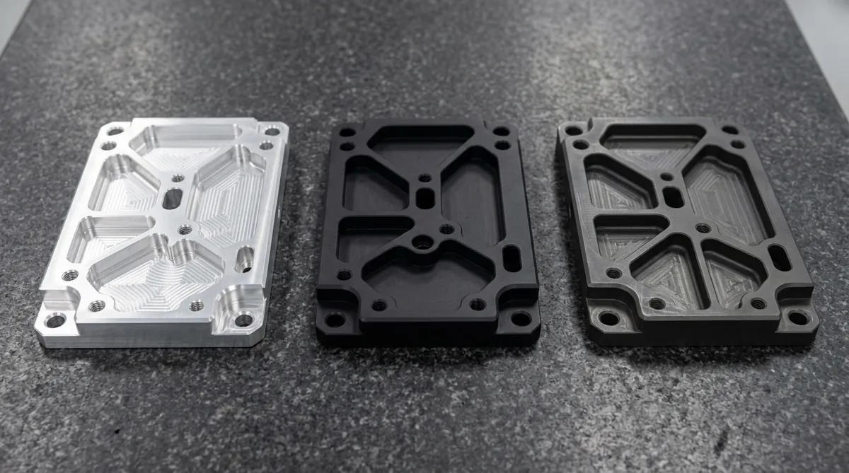
Aluminum is the undisputed metal of choice across precision CNC machining, rapid prototyping, and lightweight structural engineering. However, in its raw machined state, aluminum is susceptible to atmospheric oxidation, galvanic corrosion, surface abrasion, and cosmetic scratching. To transform raw machined components into aerospace-grade or consumer-ready hardware, aluminum anodizing is the industry-standard electrochemical surface finishing treatment.
Unlike electroplating or powder coating, which deposit an external paint or metallic layer on top of the substrate, anodizing converts the aluminum base metal itself into an integrated, ceramic-hard aluminum oxide (Al₂O₃) hexagonal cellular structure. Because this barrier layer forms organically from the aluminum substrate, it cannot peel, flake, or chip under heavy mechanical loads or thermal cycling.
Yet, when sourcing custom machined parts, design engineers and procurement teams frequently encounter dramatic price variations for anodized finishes. Why does a batch of black anodized brackets cost significantly less while another geometrically similar batch incurs higher finishing charges? In this engineering guide, AS Prototypes breaks down the six primary cost drivers of aluminum anodizing, compares Type I, Type II, and Type III Hardcoat specifications, and provides actionable Design for Finishing (DFF) strategies to minimize finishing costs.
- 1. Understanding Core Anodizing Processes (MIL-A-8625 Standards)
- 2. The 6 Primary Cost Drivers of Aluminum Anodizing
- 3. Engineering Comparison: Aluminum Anodizing & Conversion Coatings
- 4. Design for Finishing (DFF): 5 Actionable Tips to Cut Anodizing Costs
- 5. Comprehensive In-House Machining & Anodizing at AS Prototypes
- 6. Technical Engineering FAQ
1. Understanding Core Anodizing Processes (MIL-A-8625 Standards)
Industrial aluminum anodizing processes are globally standardized under military specification MIL-A-8625, categorized by the electrolyte bath chemistry, processing temperature, current density, and coating thickness:
- MIL-A-8625 Type I & IB (Chromic Acid Anodizing): The oldest military anodizing standard, utilizing a non-corrosive chromic acid bath operating at ~40°C. Produces an ultra-thin (0.5 to 2.5 µm / 0.00002 to 0.00010 in) gray-to-olive film. Because chromic acid does not attack aluminum if trapped in blind recesses or lap joints, and causes virtually zero fatigue strength degradation, Type I is strictly reserved for critical aerospace flight structures, thin-gage skins, and bonded assemblies.
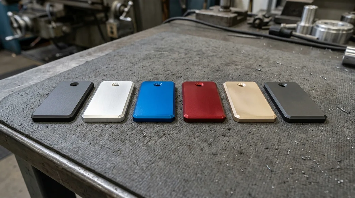
- MIL-A-8625 Type II (Commercial Sulfuric Acid Anodizing): The dominant commercial finishing process. Run at room temperature (~20°C) with standard current densities of 12–15 ASF (Amperes per Square Foot), forming a columnar porous oxide layer between 8 µm and 25 µm (0.0003 to 0.0010 in). This microscopic pore structure is highly receptive to organic and inorganic color dyes (matte black, vibrant blue, crimson red, warm gold, military green) or can be left in its natural clear-sealed satin state. Type II provides 336+ hours of salt spray corrosion resistance per ASTM B117 alongside exceptional cosmetic appeal.
- MIL-A-8625 Type III (Hardcoat / Engineered Anodizing): Carried out in a heavily chilled sulfuric acid bath (0°C to 4°C / 32°F to 39°F) under high voltage and intense current densities (24–36 ASF). Produces an ultra-dense, low-porosity ceramic layer 25 µm to 50+ µm (0.001 to 0.002 in) thick with surface hardness exceeding 450 to 550 HV0.05 microhardness. Hardcoat anodizing is engineered for severe sliding friction, military ordnance, hydraulic valve bores, subsea components, and automation wear plates (note: because the thick ceramic oxide layer can reduce tensile fatigue endurance on thin aluminum sections, avoid specifying thick Type III coatings on thin cyclic flexures).
- MIL-DTL-5541 (Chemical Conversion Coating / Alodine / SurTec 650): A non-electrolytic immersion dip generating an ultra-thin (0.1–1.0 µm) conductive chromate or trivalent chromium film. While not an anodic oxide layer, it preserves low electrical contact resistance (< 5,000 µΩ) for EMI/RFI shielding and chassis grounding while establishing an active corrosion-inhibiting base.
2. The 6 Primary Cost Drivers of Aluminum Anodizing
1. Process Selection: Type II vs. Type III Hardcoat
Type III Hardcoat anodizing typically carries a 1.8× to 2.5× price multiplier compared to standard Type II sulfuric anodizing. This pricing premium reflects substantial operational overhead: heavy industrial refrigeration units must run continuously to chill hundreds of gallons of acid solution near freezing, processing cycle times are doubled to build a 50 µm barrier layer, and high-amperage rectifiers demand heavy industrial electrical power consumption.
2. Dimensional Growth & Machining Compensation (The 50/50 Rule)
Anodizing involves both chemical penetration into the parent substrate and outward surface crystal growth according to the classic 50/50 rule:
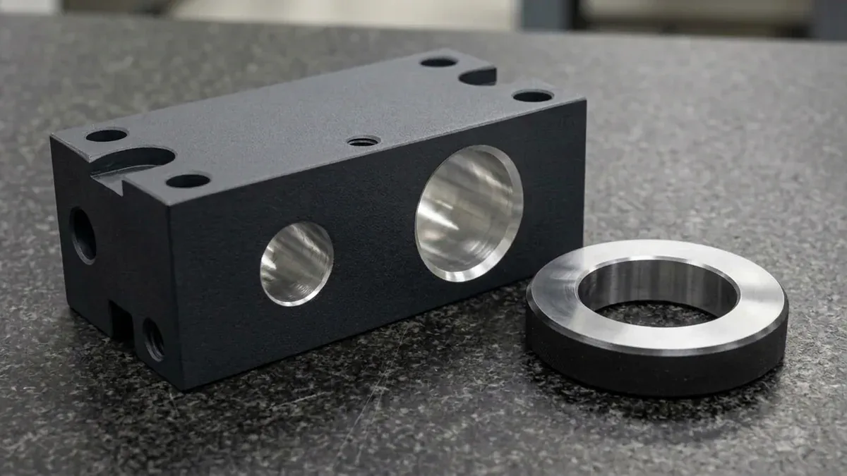
- Type II Anodizing: An 18 µm total coating consists of approximately 9 µm penetration into the base metal and 9 µm outward buildup. This creates a +18 µm diametrical expansion on solid pins/shafts and an 18 µm diametrical shrinkage inside precision bores.
- Type III Hardcoat: A standard 50 µm hardcoat causes 25 µm (0.0010 in) outward growth per surface, resulting in a +50 µm (+0.0020 in) diameter increase on shafts and 0.050 mm diametrical shrinkage inside internal bores. If a 2D engineering drawing specifies tight ±0.010 mm tolerances on bearing bores, the CNC machinist must pre-machine the bore oversized or apply selective masking. Failing to plan for hardcoat growth results in scrapped assemblies or diamond honing operations after plating.
- Edge Radius Requirements: Sharp 90° corners (< R0.5 mm) cause current concentration in the bath, resulting in fragile, chipped, or burnt edges. Maintaining an edge break or radius of at least 0.5 mm to 1.0 mm ensures a uniform, robust oxide transition.
3. Masking & Thread Protection Complexity
Because the anodic oxide layer is a dense electrical insulator and alters pitch diameters, critical mating features must often be shielded from the acid bath. Masking is the single largest manual labor cost variable in precision prototype finishing:
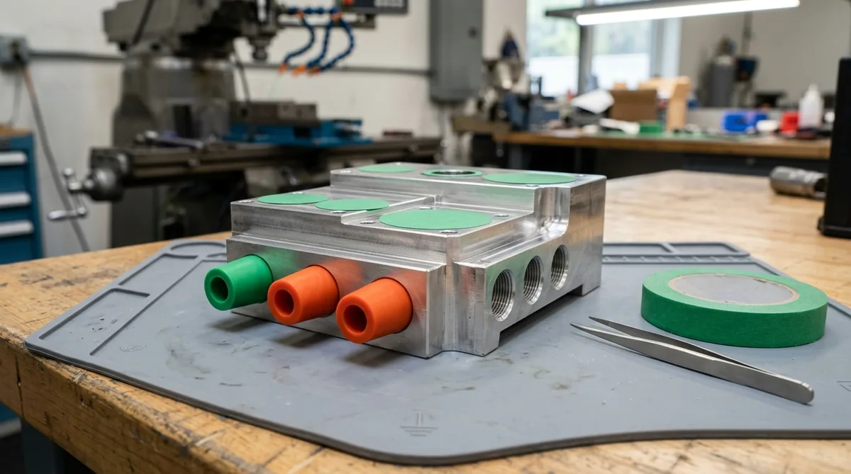
- Internal Threaded Bores & Helicoils: Standard tapped holes below M6 can often accept standard Type II buildup without binding. However, for Type III hardcoat or class 3B aerospace threads, each hole requires manual installation of a high-temperature tapered silicone plug before dipping, followed by manual de-masking and post-rinse ultrasonic cleaning.
- Bearing Fits & Dowel Pin Bores: Precision reamed bores demanding H7 tolerances must be sealed using custom die-cut green polyester discs or liquid masking polymers applied under bench magnification.
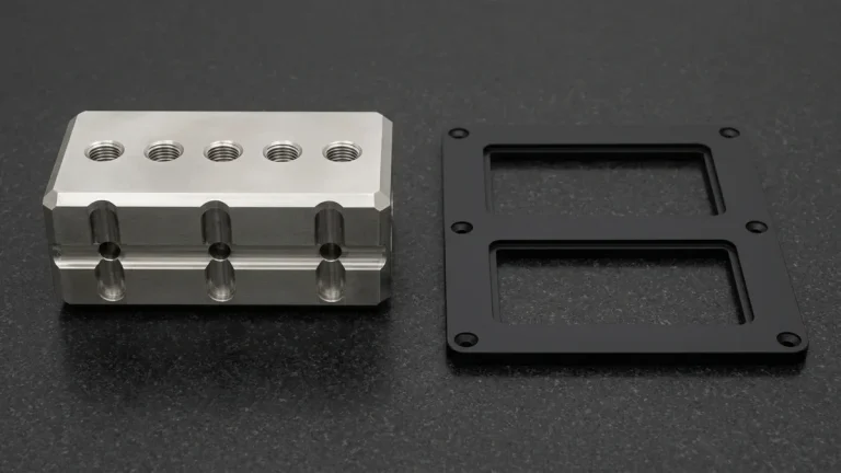
- Cost Impact: A manifold requiring 20 individual masked ports can cost three to four times more to anodize than an unmasked bracket of identical envelope dimensions, driven purely by skilled manual technician touch time.
4. Aluminum Alloy Metallurgy & Color Consistency
The metallurgical alloy series dramatically governs the chemical reaction, oxide clarity, and dye absorption inside the anodizing tank:
- 6000-Series Alloys (6061-T6, 6063, 6082): The undisputed benchmark for anodizing. With balanced magnesium and silicon content, 6061 produces crystal-clear oxide films that yield vibrant, uniform decorative colors and pristine matte black finishes with exceptional bath stability.
- 7000-Series Alloys (7075-T6): High zinc and copper alloying elements impart an inherent olive-gray or bronze undertone to the anodic layer. While Type III hardcoat on 7075 achieves outstanding abrasion resistance, cosmetic color matching across batches requires stringent tank temperature and chemistry monitoring.
- 2000-Series Alloys (2024-T3) & Die-Castings (A380, ADC12): High copper (> 4%) or high silicon (> 7%) contents inhibit dense oxide formation and cause chemical pitting. Castings yield a dull, mottled charcoal appearance and cannot support bright decorative colors.
- 5000-Series (5052-H32): Outstanding corrosion resistance and excellent, uniform response to both clear and black anodizing, widely utilized for precision sheet metal enclosures.
5. Surface Pre-Treatment: Bead Blasting vs. Optical Polishing
Because anodic oxide is translucent and conformal, anodizing accentuates rather than conceals underlying machining marks, chatter, and surface flaws:
- Bead Blasting (#100 to #150 Glass Beads): The most cost-efficient pre-treatment. Blasting under controlled air pressure creates an isotropic, non-directional satin matte texture that effectively camouflages subtle CNC toolpaths while creating a premium tactile feel.
- Optical Hand Polishing (SPI A-2 / Mirror Buffing): Producing high-gloss automotive trim or consumer electronics bevels requires progressive mechanical buffing through 3000-grit diamond pastes before electro-brightening and anodizing, adding substantial skilled labor to the invoice.
6. Racking, Electrical Contact Points & Tank Lot Charges
Every anodized part must be securely clamped to a titanium or aluminum racking spline to conduct heavy electrical current during the electrochemical cycle:
- Unavoidable Contact Marks: Where the titanium racking finger firmly clamps the workpiece, the chemical bath cannot reach the metal. This leaves a small, bare contact mark (typically 1 to 3 mm wide). Specifying non-critical racking zones (such as inside a counterbored mounting hole or hidden interior face) directly on your 2D drawings prevents cosmetic rejects.
- Tank Lot Minimums: Commercial plating lines operate with fixed minimum lot charges (per process tank run) regardless of whether you process one prototype part or thirty. Consolidating different prototype parts into standard batch colors (such as Matte Black or Clear) spreads the fixed lot fee across the entire bill of materials.
3. Engineering Comparison: Aluminum Anodizing & Conversion Coatings
The table below summarizes the technical specifications, mechanical properties, and relative cost multipliers across industrial aluminum finishing processes at AS Prototypes:
| Finishing Specification | Coating Thickness | Microhardness (HV0.05) | Dimensional Growth | Corrosion Resistance (ASTM B117) | Cost Factor | Typical Applications |
|---|---|---|---|---|---|---|
| MIL-A-8625 Type I (Chromic) | 0.5 – 2.5 µm (0.00002 – 0.0001 in) | Substrate dependent | Negligible (< 1 µm) | 336 Hours | 1.3× – 1.6× | Aerospace fatigue-critical spars, structural bonding, thin sheet metal |
| MIL-A-8625 Type II (Standard) | 10 – 25 µm (0.0004 – 0.0010 in) | 250 – 350 HV0.05 | +5 to +12 µm / surface | 336 Hours | 1.0× (Baseline) | Consumer electronics, drone arms, medical brackets, robotic frames |
| MIL-A-8625 Type III (Hardcoat) | 25 – 50 µm (0.0010 – 0.0020 in) | 450 – 550 HV0.05 | +12 to +25 µm / surface | 1,000+ Hours | 1.8× – 2.5× | Hydraulic pistons, marine actuators, linear wear rails, military gear |
| Type II + Precision Masking | 10 – 25 µm (selective) | 250 – 350 HV0.05 | 0.0 µm on masked surfaces | 336 Hours (exposed) | 1.5× – 3.0× | Manifolds with slip-fit bearing bores and bare ground contact pads |
| MIL-DTL-5541 (Alodine 1200S) | 0.2 – 1.0 µm (< 0.00004 in) | Conductive chemical film | 0.0 µm (Negligible) | 168 Hours | 0.7× – 0.9× | EMI/RFI shielding cavities, RF communication housings, electrical grounding |
4. Design for Finishing (DFF): 5 Actionable Tips to Cut Anodizing Costs
- Standardize on Universal Tank Colors: Specifying custom Pantone or RAL color matches requires dedicated dye tank formulation, test coupons, and bath titration fees. Selecting standard high-volume finishes—such as Bead-Blasted Matte Black or Clear Natural—utilizes existing automated line capacity and cuts finishing costs by up to 35%.
- Consolidate and Minimize Masking Requirements: Avoid calling out masking on standard non-critical tapped holes (M4, M5, M6). Standard thread engagement clearances easily accommodate normal 10–15 µm Type II oxide buildup. Restrict labor-intensive silicone plugging strictly to tight slip-fit bearing bores (H7) and electrical grounding pads.
- Explicitly Define Non-Cosmetic Racking Locations: Indicate acceptable racking clamp zones directly on your 2D engineering drawing (e.g., inside an unexposed blind cavity, mounting tab, or internal tapped hole). This eliminates fixturing trial-and-error and prevents cosmetic rejection.
- Design Uniform Edge Breaks to Prevent Arcing: Avoid razor-sharp knife edges (< R0.3 mm). High electrical current density concentrates at sharp corners, leading to localized “burning,” brittle oxide cracking, or premature coating breakdown. Incorporating a modest R0.5 mm fillet ensures uniform, dense oxide deposition.
- Leverage Early DFM Reviews Before Cutting Metal: Involve manufacturing engineers during the CAD drafting stage. Our team conducts complimentary DFM engineering reviews to calculate pre-machining bore offsets and verify alloy selection before chips fly.
5. Comprehensive In-House Machining & Anodizing at AS Prototypes
At AS Prototypes, we provide seamless, single-source manufacturing. Rather than coordinating separate machine shops, bead-blasting vendors, and plating subcontractors, our facility executes multi-axis CNC milling, pre-anodize tolerance compensation, automated bead blasting, custom color anodizing, and laser marking under one unified engineering management system. Every production batch is verified using calibrated eddy-current coating thickness gauges, thread plug gauges, and comprehensive Zeiss CMM inspection reports (available upon request).
6. Technical Engineering FAQ
Type III hardcoat penetrates 50% into the aluminum substrate and builds 50% outward. A 50 µm total coating adds approximately 25 µm (+0.025 mm) outward growth per surface, which shrinks internal bore diameters by ~0.050 mm. AS Prototypes pre-machines bearing bores oversized or applies precision masking to hold tight dimensional fits. For threaded holes, standard threads accept Type II growth, while Type III requires pre-tapping oversized or silicone plugging.
Type III hardcoat produces an ultra-dense, ceramic-like aluminum oxide layer with surface microhardness ranging from 450 to 550 HV0.05 (Vickers microhardness). This provides exceptional sliding wear and abrasion resistance, widely specified for military ordnance, hydraulic valve bodies, and aerospace slide tracks.
No. Because alloying elements (such as copper in 2024 and zinc in 7075) react differently with the acid electrolyte, 7075 exhibits a natural bronze/charcoal undertone compared to the crystal-clear oxide of 6061. Anodizing them simultaneously will yield noticeable cosmetic color mismatches. For multi-part assemblies requiring identical color shades, standardizing on the same alloy series (e.g., 6061-T6) is strongly recommended.
Standard CNC aluminum prototypes with Type II or Type III hardcoat anodizing are completed, measured, and inspected within 7 to 12 business days. This turnaround accounts for precision CNC machining, surface bead-blasting pre-treatment, tank chemistry calibration, and final dimensional verification.
Specify Verified Surface Finishes on Custom Precision Components
Ensure dimensional allowance control, thread masking accuracy, and MIL-A-8625 or ASTM surface compliance from raw billet machining through final finishing. Upload your 3D CAD models and 2D prints for a complete engineering DFM review.
Upload CAD & Drawings for Finishing DFM Review