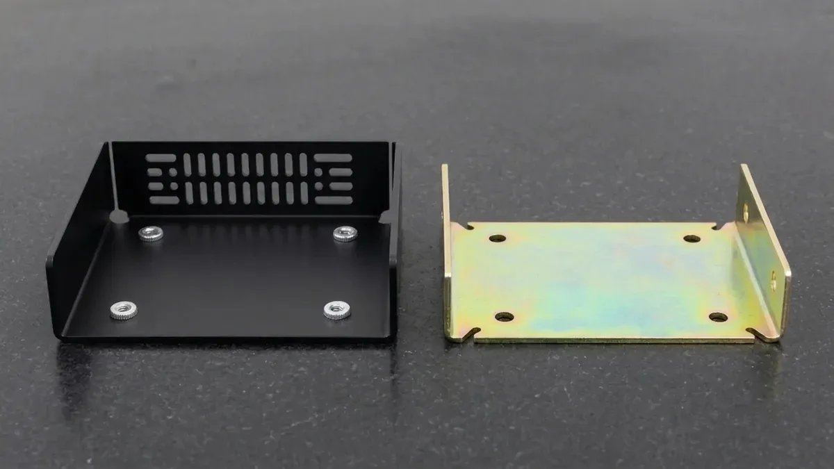
Sheet metal fabrication is one of the most versatile and cost-effective manufacturing processes for producing durable, lightweight, and electrically conductive parts. From 19-inch server chassis and outdoor telecommunication enclosures to automotive battery brackets and medical diagnostic carts, sheet metal components form the structural backbone of modern hardware engineering.
However, prototyping sheet metal parts historically presented a major dilemma: high-volume stamping demands custom progressive dies and deep-draw tooling that require substantial upfront tooling investment and take weeks to fabricate. In rapid product development, investing in hard tooling before locking in final CAD designs is a severe financial and schedule risk.
Fortunately, modern rapid sheet metal prototyping eliminates this dependency. By integrating high-power CNC fiber laser cutting, precision multi-axis press brakes, automated hardware insertion, and robotic laser welding, manufacturers can now produce functional, production-representative sheet metal prototypes in 4 to 8 business days without dedicated hard tooling. In this comprehensive guide, AS Prototypes breaks down the essential engineering workflows, material trade-offs, and Design for Manufacturability (DFM) rules for quick-turn sheet metal prototypes.
- 1. The Modern Rapid Sheet Metal Prototyping Workflow
- 2. Sheet Metal Prototyping Material Selection & Mechanical Matrix
- 3. 5 Core DFM Rules for Precision Sheet Metal Bending & Laser Cutting
- 4. Hardware Insertion & Precision Assembly
- 5. Why Choose AS Prototypes for Your Sheet Metal Prototypes?
- 6. Technical Engineering FAQ
1. The Modern Rapid Sheet Metal Prototyping Workflow
Rather than cutting custom stamping dies, modern prototype shops utilize a zero-tooling digital manufacturing sequence:
- 3D CAD Unfolding & Flat Pattern Generation: Translating 3D solid models into 2D flat blanks using calibrated K-factor bend allowances tailored to specific material grades and tooling V-die widths.
- CNC Fiber Laser Cutting: Slicing complex outer perimeters, internal cutouts, ventilation louvers, and mounting holes with ±0.05 to ±0.10 mm positional accuracy.
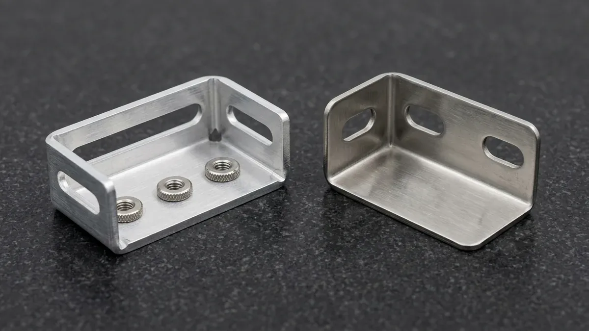
- Deburring & Edge Conditioning: Automated vibratory tumbling or rotary brush sanding to remove microscopic laser dross and razor-sharp burrs.
- Multi-Axis CNC Air Bending: Forming progressive flanges, hems, and offsets using standardized, staged precision-ground tooling.
- Hardware Insertion: Hydraulic pressing of self-clinching PEM fasteners, threaded standoffs, studs, and nuts.
- Fabrication & Joining: Precision TIG/MIG welding, spot welding, or continuous handheld fiber laser welding ground flush.
- Surface Finishing: Applying corrosion-resistant conversion coatings, anodizing, powder coating, or silk-screen branding.
2. Sheet Metal Prototyping Material Selection & Mechanical Matrix
Selecting the optimal sheet alloy balances formability, strength-to-weight ratio, weldability, and corrosion resistance. Below is an engineering comparison of the primary sheet materials processed in our facility:
| Material Grade | Yield Strength (MPa) | Min Bend Radius (R/t) | Formability & Welding | Primary Engineering Applications |
|---|---|---|---|---|
| Al 5052-H32 | 195 | 1.0t | Excellent / TIG & MIG weldable | Chassis enclosures, brackets, marine brackets |
| Al 6061-T6 | 276 | 3.0t – 6.0t (cracking risk; use 5052-H32 for bent chassis) | Moderate / Good weldability | High-strength structural brackets, busbars |
| SS 304 / 316L | 240 – 290 | 1.0t – 1.5t | High work-hardening / Excellent TIG | Medical housings, food processing, IP67 boxes |
| Cold Rolled SPCC / 1018 | 210 | 0.8t – 1.0t | Superb / Spot & seam welding | Powder-coated electronic racks, automotive panels |
| Copper C11000 | 190 – 260 | 0.5t – 1.0t | High ductility / Soldering & brazing | EV power busbars, grounding clips, heat spreaders |
3. 5 Core DFM Rules for Precision Sheet Metal Bending & Laser Cutting
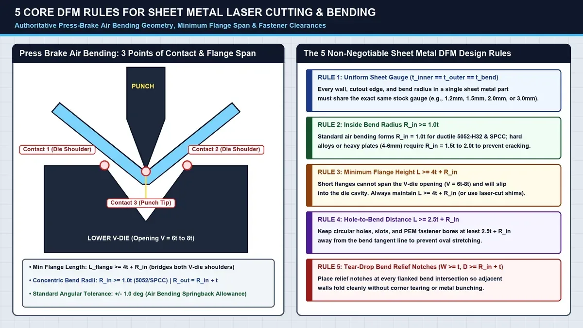
To avoid tearing, edge distortion, and secondary tooling rework on CNC press brakes, hardware designers should adhere to five essential sheet metal DFM guidelines:
- 1. Uniform Inside Bend Radius (R ≥ t): Design all bends across a single part with the same internal radius (matching material thickness t). Standardized punch nose radii allow the press brake operator to complete all bends in a single machine setup without tooling changeovers.
- 2. Minimum Flange Length (L ≥ 4t + R): If a bend flange is too short, the sheet will slip into the die V-opening before reaching the bottom of the stroke, causing severe angular error and cosmetic gouging.
- 3. Hole-to-Bend Safe Clearance (d ≥ 2.5t + R): Placing punched or laser-cut holes too close to a bend line exposes them to tensile plastic deformation, stretching circular holes into distorted ovals.
- 4. Bend Relief Notches: When a bend occurs adjacent to a flat flange, tear stresses tear the raw material at the edge. Always incorporate rectangular or teardrop relief notches with a width ≥ t and depth ≥ R + t.
- 5. Respect Rolling Grain Direction: Bending parallel to the raw sheet’s longitudinal rolling grain significantly increases tensile cracking risks, especially on hardened temper alloys like Al 6061-T6. Whenever possible, orient critical bend lines perpendicular or at 45° to the sheet grain direction.
4. Hardware Insertion & Precision Assembly
Threaded connections in thin sheet metal cannot rely on tapped holes because the gauge does not provide enough thread engagement. At AS Prototypes, we integrate automated insertion presses for self-clinching fasteners:
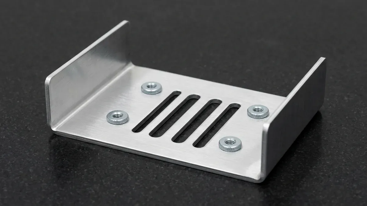
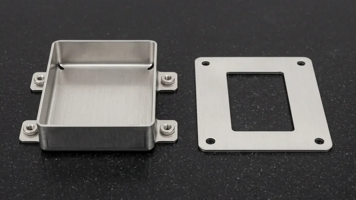
- Self-Clinching PEM Fasteners: Threaded studs, blind standoffs, and captive nuts pressed into laser-cut holes. The displaced ductile metal flows into a special undercut shank, providing high torque-out and push-out resistance without requiring welding or heat.
- Laser Welding & Seam Grinding: For waterproof IP65/IP66 enclosures, continuous handheld fiber laser welding produces narrow, aesthetically clean weld beads with minimal heat distortion, easily sanded flush for invisible seamless corners.
- Surface Finishing Solutions: Complete in-house surface finishing services including chromate conversion (MIL-DTL-5541), sulfuric anodizing, heavy-duty architectural powder coating (RAL/Pantone matching), and silk-screened artwork.
5. Why Choose AS Prototypes for Your Sheet Metal Prototypes?
At AS Prototypes, our Shenzhen manufacturing facility bridges the gap between digital prototype validation and full-scale production. With fiber laser cutting up to 20 mm thickness, multi-axis CNC press brakes, dedicated stamping presses, robotic welding, and 2D optical flat-pattern scanning, dedicated checking fixtures, and full mating assembly fit-up verification, we deliver sheet metal prototypes held to ±0.1 mm tolerances in 4 to 8 business days.
6. Technical Engineering FAQ
To prevent edge bulging or tear-out during press brake bending, pierced or laser-cut hole edges must maintain a minimum distance of d ≥ 2.5t + R from the nearest bend tangent line, where t is sheet thickness and R is inside bend radius.
6061-T6 has low ductility (10–12% elongation) and high precipitation-hardened yield stress. Bending with a tight inside radius (R < 3.0t–6.0t) or bending parallel to the rolling grain direction induces severe tensile surface cracking. Always specify ductile 5052-H32 for bent sheet metal chassis (which bends cleanly at R ≥ 1.0t), or design R ≥ 3.0t–6.0t perpendicular to the grain if 6061-T6 is mandatory.
At AS Prototypes, comprehensive DFM reviews and quotations are completed within 24 hours. Ex-factory prototype sheet metal fabrication batches are completed in 4 to 8 business days, followed by 3 to 5 business days international air transit.
Engineer Precision Custom Sheet Metal Enclosures & Brackets
Eliminate bend springback, hole distortion, and assembly interference before cutting metal. Upload your 3D CAD files (STEP/IGES) and 2D flat-pattern drawings for a dedicated sheet metal DFM review and custom production quotation.
Upload CAD Files for Sheet Metal DFM & Quote